
Hino 300 Series Electrical Wiring Diagram Manual 2007 – WU300 XZU303-XZU437 Truck Workshop Wiring PDF
Original price was: $59.95.$39.95Current price is: $39.95.
Complete Hino 300 Series electrical wiring diagram manual (April 2007) covering WU300, WU302, WU340, WU410, WU412, WU420, WU422 and XZU303-XZU437 trucks. Relay locations, harness routing, connector pinouts, connector part numbers and full overall electrical schematics in a single 144-page PDF.
Description
Hino 300 Series Electrical Wiring Diagram Manual – 2007 Edition
The Hino 300 Series Electrical Wiring Diagram manual is the wiring reference used to trace, diagnose and repair the complete electrical system of Hino 300 light and medium-duty trucks. Published by Hino Motors, Ltd. with an April 2007 first printing, this 144-page PDF walks the technician from the fuse and relay layout through every harness, splice, connector cavity and ground point on the vehicle. Body builders, fleet workshops and independent electrical specialists rely on documentation of this type when installing PTO equipment, retro-fitting accessories or chasing intermittent faults that no generic OBD scan will resolve.
File Details
- Manual type: Electrical Wiring Diagram Manual
- Brand / Publisher: Hino Motors, Ltd.
- Model family: Hino 300 Series
- Language: English
- Page count: 144
- File format: PDF
- First printing: April 2007
- Copyright: 2007 Hino Motors, Ltd.
Chapters Covered
- 1. Introduction
- 2. How To Use This Manual
- 3. Abbreviations
- 4. Location Of The Relays
- 5. Routing Of Electrical Wiring
- 6. List Of Connectors
- 7. Connector Part Number
- 8. Diagram Of The Overall Electrical Wiring
Introduction, How To Use & Abbreviations
The opening sections explain the scope of the manual, how each section interlocks with the wiring schematics, and list every abbreviation used throughout — A/C, A/T, DC, DLC3, DPR (DPF), ECU, EDU, EGR, FL, ISC, J/B, LCD, LH, LHD, M/T, PTO, R/B, RH, RHD, SW, TEMP., VSV, w/ and w/o. Understanding this short glossary up front saves time later when you are cross-referencing a connector code on a schematic against a relay block callout on the bench.
Location Of The Relays
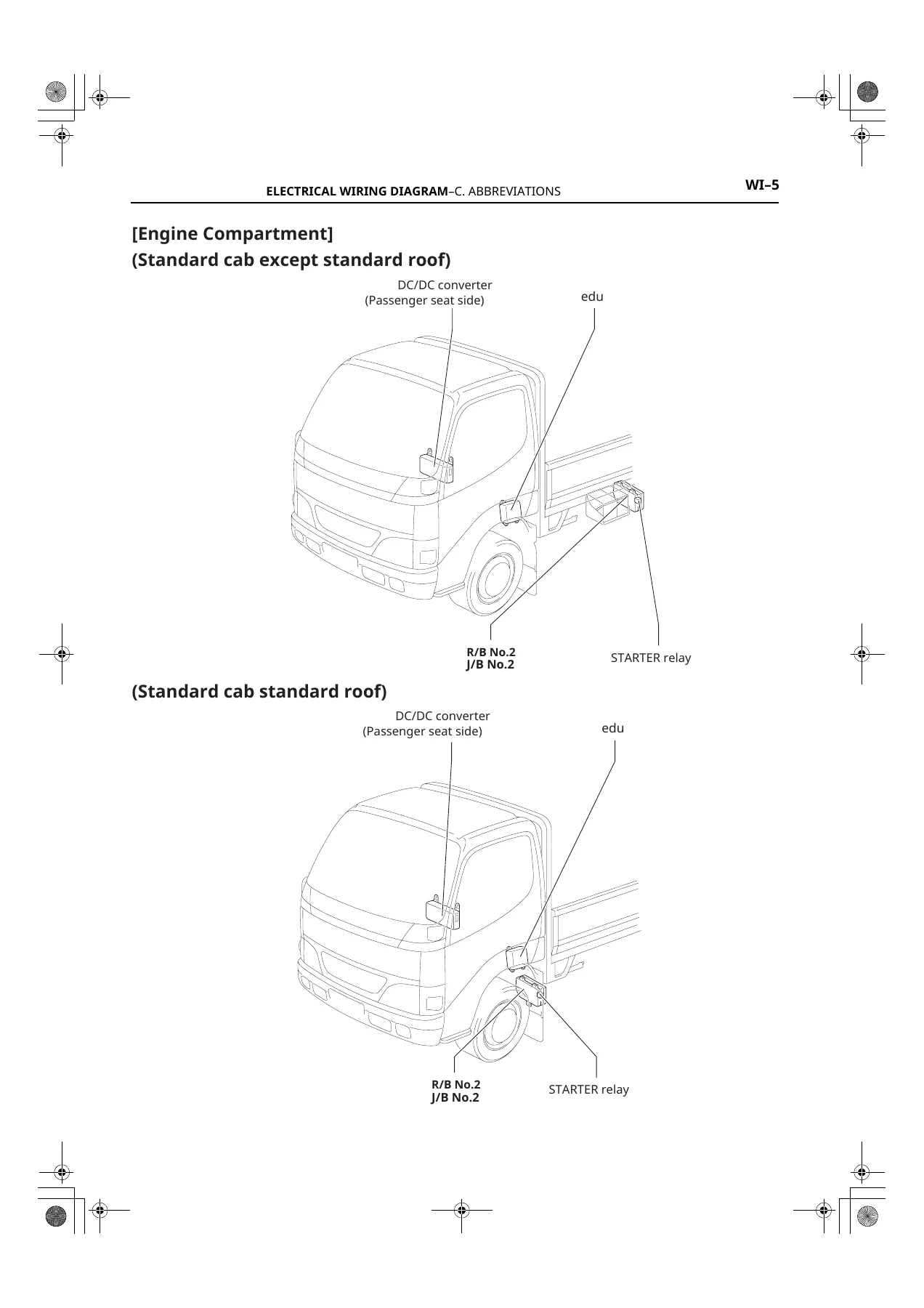
This chapter pinpoints every relay, relay block and electronic control unit on the truck. Coverage includes R/B No.1 and J/B No.1 under the glove box, and R/B No.2 and J/B No.2 at the front left side under the rear cover. Named relays and components include the flasher relay, HORN relay, H-LP relay, TAIL relay, STOP, HAZ-HORN, FR MIST, HEAD, CLEANER, AM2, ENG (12V), STA, A/C, IG1, EDU-B, PTO relay, E-FAN relay, MAIN relay PWR TILT, MAIN relay MTR ABS, ABS SUN MAIN relay, Relay IG1-3, EDU relay, DC-DC relay, MAIN SPARK PLUG relay, and pre-heater relay. Fuse callouts such as 80A HIGH, 80A STA, 100A STA, 40A HEAD, 30A AM1, 30A DC-DC1/2, 30A ABS-SOL, 30A HTR, 30A PWR TILT, 40A MAIN, 50A MAIN 2/3, 40A SPARK PLUG and 50A ABS-MTR are also mapped for each variant.
Routing Of Electrical Wiring
Engine-compartment, instrument-panel and bodywork harness routing is illustrated for both left-hand drive and right-hand drive trucks, across Standard Cab and Wide Cab bodies, and for the W04D and N04C engine families. Components located include the alternator, starter and starter relays, A/C magnetic clutch, camshaft and crankshaft position sensors, EDU 1 and EDU 2, EGR valve position sensor, exhaust gas temperature sensor, differential pressure sensor, ABS speed sensors and ABS actuator, fuel pressure sensor, fuel temperature sensor, fuel sender, fuel filter warning switch, injectors No.1 through No.4, ISC valve, suction control valve, VSV (Exhaust Brake), VSV (Intake Latch), turbocharger control actuator, turbo pressure sensor, cab tilt control switch, oil pressure switch, water temperature sender and switch, wiper motor, headlights LH/RH, fog lights, front turn signals, side turn signals, license plate lights, reverse light switch, brake vacuum warning switch, door courtesy switches, door lock motors, power window motors and switches, power glass master switch, speaker LH/RH, warning buzzers, PTO solenoid valve, PTO transmission neutral position switch, PTO controller No.1 and No.2, tachograph, radio/cassette player and integration relay. Harness joints and grounds such as IA2, IB4, IE1, IE2, IE3, IF, IF1, IF2, IG3, II2, BA4, BA5, BA7, BC2, BC4 are cross-referenced to physical locations in the cab, engine bay and frame.
List Of Connectors & Connector Part Number
Two dedicated chapters catalogue every harness connector shape and cavity count, then list the corresponding part number for each. Connector codes span A, B, C, D, E, F, G, H, I, J, K, L, M, N, O, P, Q, R, S, T, V and W prefixes, with pictorial cavity numbering for 2-pin, 3-pin, 4-pin, 6-pin, 8-pin, 10-pin, 12-pin, 16-pin, 22-pin, 24-pin and larger multi-pin housings. Wire-to-wire mating connectors, docking connectors J28 through J48, and the corresponding 90980-xxxxx and 82824-xxxxx part numbers are listed so you can order the correct replacement terminal housing without guessing. This is the section that lets a harness repair actually match the factory connector rather than improvising one that almost fits.
Diagram Of The Overall Electrical Wiring
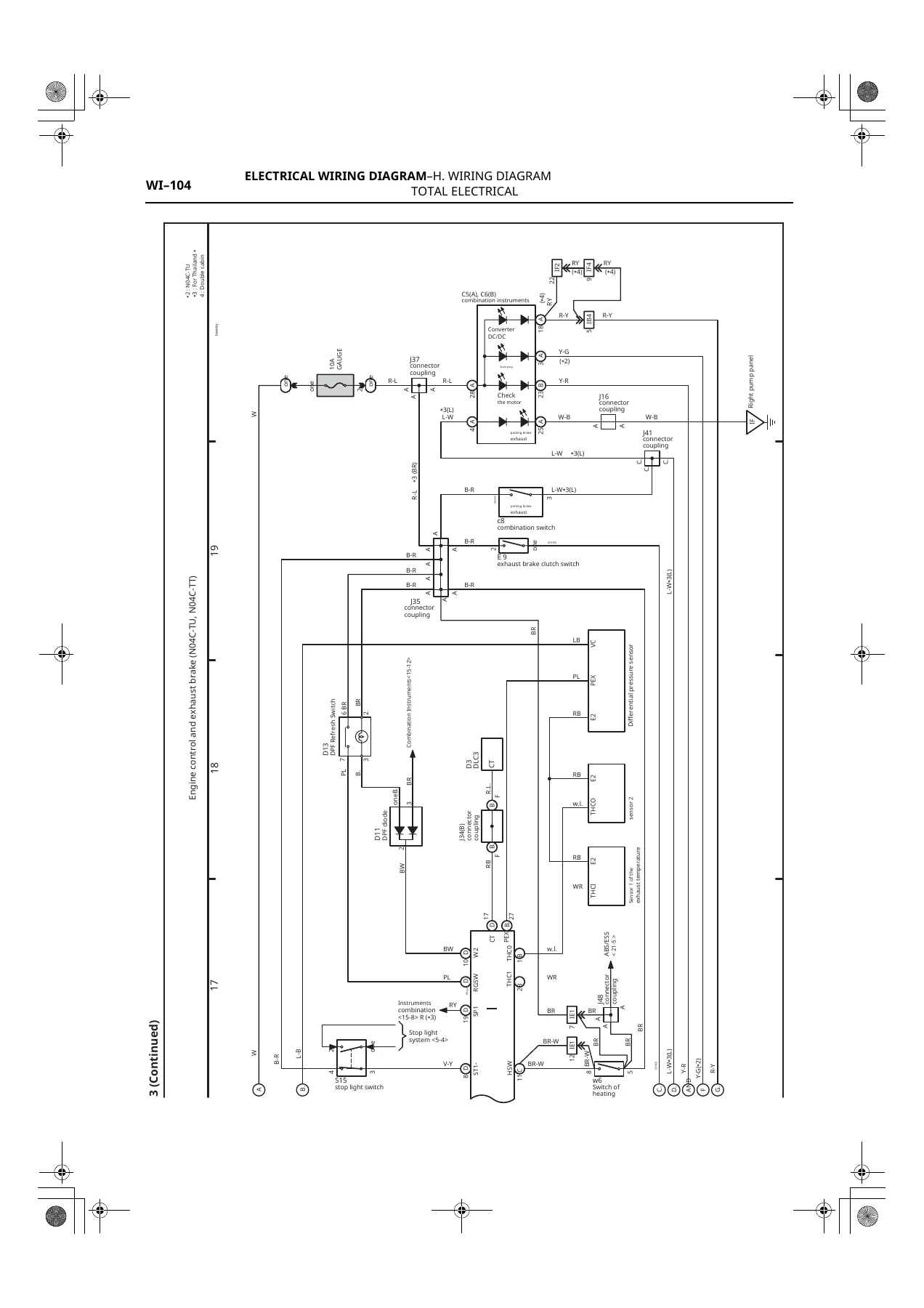
The final chapter contains the complete overall electrical schematics. Circuits are broken out by system and variant and cover power source, seat belt and warning, reverse light, front hazard/headlight beam level control, rear fog light, control and exhaust brake, A/T bag (SRS airbag), ABS and starting control, and more. Each sheet shows wire colours (B, W, R, Y, G, L, BR, LG, P, V, GR, O, SB and combinations such as B-W, R-L, Y-G, G-R, W-B), fuse and relay reference numbers, splice points, ground symbols, connector codes and pin numbers, so a circuit can be traced end-to-end without leaving the page.
Model Coverage
This wiring diagram manual covers the following Hino 300 Series model ranges:
- WU300, WU302, WU340, WU410, WU412, WU420, WU422 series
- XZU303, XZU306, XZU307, XZU343, XZU347, XZU405, XZU407, XZU413, XZU415, XZU417, XZU423, XZU425, XZU427, XZU435, XZU437 series
Coverage extends across Standard Cab and Wide Cab, Standard Roof, Left Hand Drive (LHD) and Right Hand Drive (RHD) configurations, with dedicated wiring variations for the W04D and N04C engine families, plus Thailand-specific variants (TR, TS, TT, TU, TV, TP, TW, TF) and W04D variants (J, TM, TN).
Why This Hino 300 Wiring Manual Pays For Itself
A single misdiagnosed electrical fault on a Hino 300 can cost more in labour and parts-cannon swapping than this manual costs outright. With the complete overall electrical wiring diagram in front of you, you can follow a suspected circuit from battery positive, through the fuse and relay, out to the load and back to the ground in minutes rather than hours. That means faster turnaround on trucks that need to be earning, more accurate parts ordering, and cleaner installs when you are adding body equipment, PTO controllers, beacons, reversing cameras or auxiliary lighting on the Hino 300 chassis.
Whether you are a Hino dealer technician, a fleet maintenance shop, an auto-electrician or a workshop handling XZU and WU series trucks, this 2007 Hino 300 electrical wiring diagram manual gives you the same wiring data the factory used to build the truck. It covers the systems that matter in daily repair work: charging and starting, lighting, engine management, ABS, airbag, exhaust brake, PTO control, air conditioning, power windows, door locks, wipers and instrument cluster.
Delivered as an instant PDF download after checkout, the manual is ready to open on any laptop, tablet or smartphone and can be printed page by page for the workshop floor. No shipping, no waiting, no subscription — just the full 144-page Hino 300 Series wiring reference in your hands the moment you need to pick up a meter.
IMAGES PREVIEW

Reviews
There are no reviews yet.