
Hino FG8J FL8J FM2P FM8J SG8J Electrical Wiring Workshop Manual
Original price was: $39.95.$23.95Current price is: $23.95.
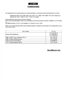
Complete electrical wiring workshop manual for Hino FG8J, FL8J, FM2P, FM8J and SG8J series trucks equipped with J08E and P11C engines – system-by-system wiring diagrams, connector pinouts, junction connectors, relay and fuse block layouts, and full connector index. Pub. No. S1-MFGE03A EWD.
Description
Hino FG8J, FL8J, FM2P, FM8J & SG8J Electrical Wiring Workshop Manual
This is the dedicated electrical circuit workshop manual for the Hino FG8J, FL8J, FM2P, FM8J and SG8J series trucks equipped with the J08E and P11C engines. Rather than a general service guide, this publication is built specifically around the electrical architecture of these chassis – the harness routing, the connectors, the junction points, the fuse and relay layout, and the circuit paths that tie every system together. It is the document a technician reaches for when a fault has to be traced rather than guessed at.
File Details
- Manual type: Electrical Wiring Workshop Manual (EWD)
- Brand / Publisher: Hino Motors, Ltd.
- Publication number: S1-MFGE03A EWD ’14-8
- Models covered: FG8J, FL8J, FM2P, FM8J, SG8J
- Engines covered: J08E (incl. J08E-CR and J08E-NB variants) and P11C
- Language: English
- Page count: 202 pages
- File format: PDF
Chapters Covered
The manual follows Hino’s chapter numbering, opening with the general introduction and abbreviation list, then moving into the two large reference sections that make up the bulk of the file – the wiring diagrams and the connector data – before the location and block references:
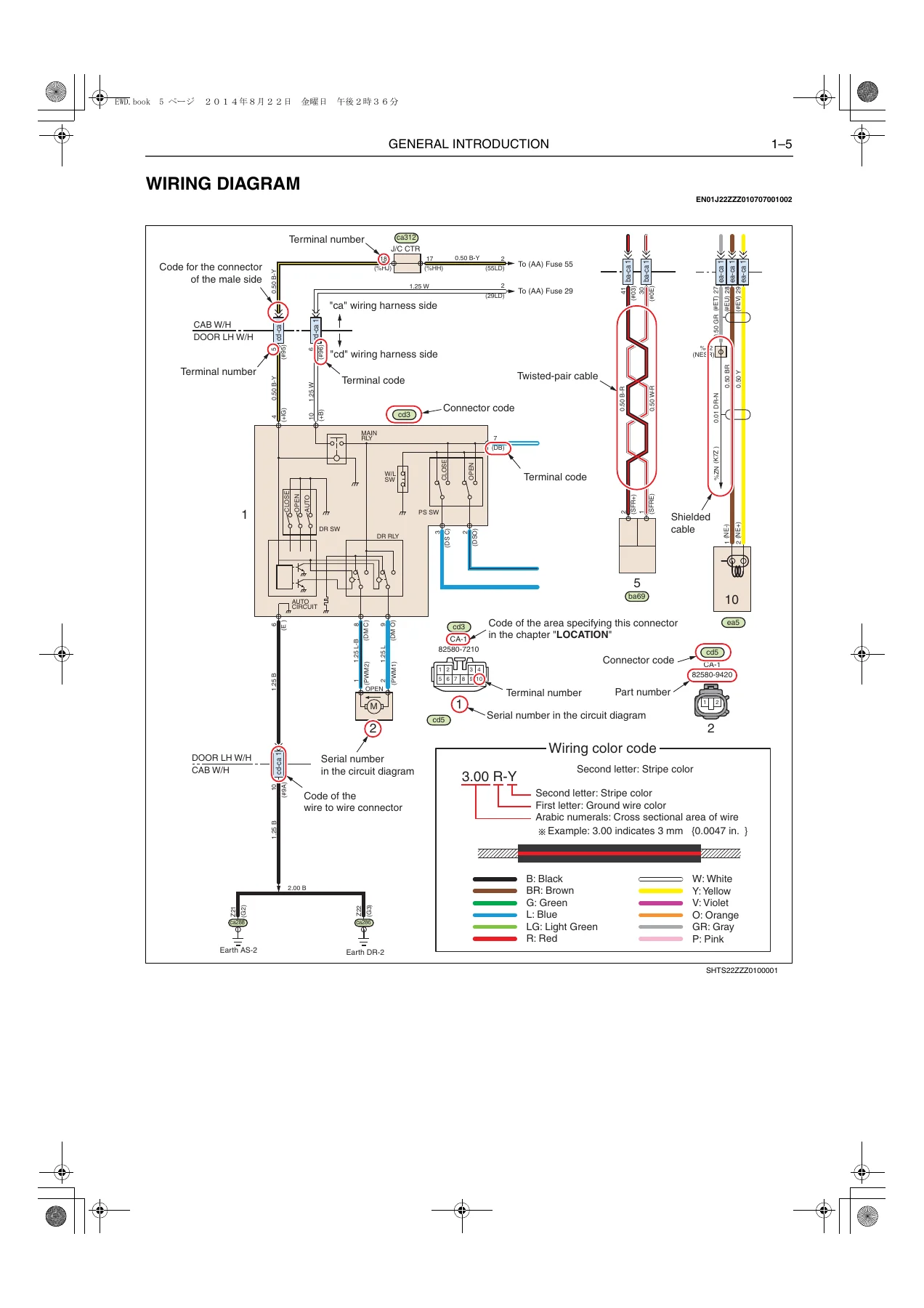
- General Introduction – how to use the manual, list of abbreviations, wiring diagram conventions, wire-to-wire connector key, junction connector key, connector location key, fuse and relay box key, connector index
- Wiring Diagram According to System – wiring harness codes plus the full circuit set: A01 Power Supply, A03 Engine Starting, A07 Charging, A08 ETC Spare Power Supply, B01/B02/B03 Ground Circuits, C03 Meter, C06 Tachograph, C07 Hour Meter, C08 Coolant Level Warning, D01 Headlight, D04 Turn Light, D05 Stop Light, D06 Tail Light, D07 Backup Light, D10 Fog Light, D11 Working Light, D12 Room Light, E05 Cigarette Lighter, E06 Radio/Audio, E10 Horn, E11 Power Window, E13 Wiper and Washer, E15 Power Door Lock, F02 Air Conditioner, G01/G02 Common Rail No.1, G03/G04 Common Rail No.2 (Exhaust Brake), G06 Common Rail No.4 (PTO), G07 Common Rail No.2 (Exhaust Brake, J08E-NB), G41 Engine Stop, H01 ABS, H02 Inter-Axle Differential Lock, H08 ES Start, J01 M009 Transmission, L01 Transmission PTO Control, N01 Diagnosis Monitor, N02 Diagnosis Connector (16 pin), N03 CAN Communication (Vehicle)
- Wire to Wire Connector – the harness-to-harness joint list with part numbers, cavity counts and terminal positions
- Junction Connector – junction connector list with circuit and area references
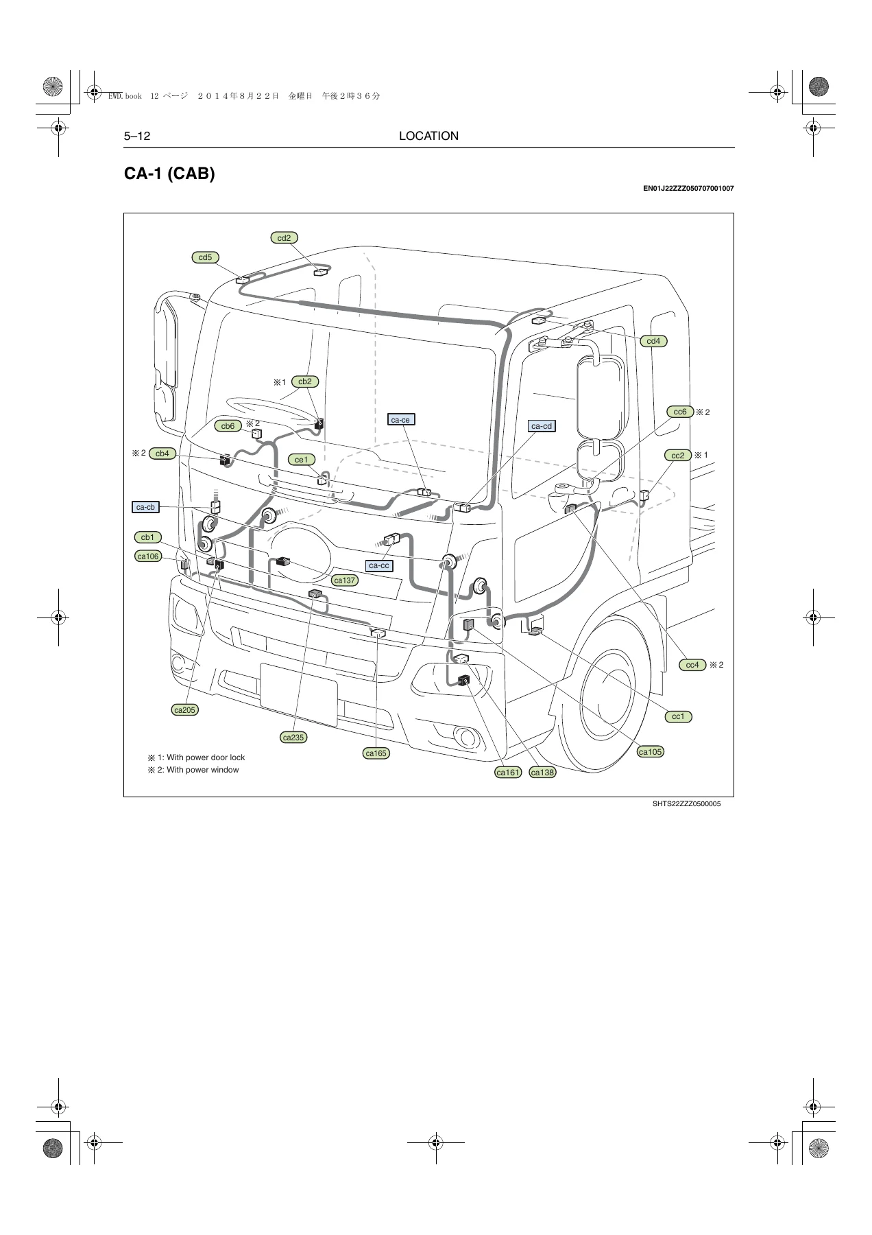
- Location – quick reference by steering position, model and specification, then sectional connector location drawings: IP-1 through IP-4 instrument panel views, CA-1 cab, EG-1 through EG-7 engine views, and RR-1 through RR-4 rear views
- Relay Location / Fuse and Relay Block – cab relay and component locations, chassis relay location, fuse and relay alignment, fusible link block and alignment, wire-to-wire box alignment
- Index – full connector index covering electrical equipment connectors, wire-to-wire connectors and junction connectors
What the structure tells you is that this manual was designed around troubleshooting flow. You start at the index, jump to the circuit that matches the complaint, follow the wire colour and cross-section notation to the connector code, then look up that connector’s physical location and pin numbers in the connector chapter. Every system on the truck is drawn the same way, so once the notation is understood the whole vehicle becomes readable – power supply and starting at one end, CAN communication and diagnostics at the other, with ABS, common rail, transmission control, exhaust brake and PTO circuits all mapped in between.
How the Circuit Diagrams Are Organised
Each circuit page is drawn with the cab side wiring on one side and the chassis side wiring on the other, separated by harness boundaries. Wire colour codes follow the standard Hino convention – a two-colour callout where the first colour is the ground wire and the second is the stripe – paired with a cross-sectional area figure so you know the conductor size as well as its colour. Terminal numbers are printed at each connector, connector codes are shown in oval callouts, and each diagram carries a serial number so you can confirm you are looking at the right page for the vehicle specification. Where a system differs by model or engine – for example J08E-CR versus J08E-NB versus P11C common rail circuits – separate diagrams are provided and footnotes mark which variant applies.
Connector and Location Data
The connector index is thorough: it lists the connector code, connector name, part number, the circuit or area it belongs to, and in many cases the page reference for the location drawing. Wire-to-wire connectors are listed with both male and female part numbers, the harnesses they join, and the model-specific applicability. Junction connectors carry the same detail plus the internal connection layout. On top of that, the location chapter provides illustrated views of the cab, instrument panel, engine bay and rear chassis with every connector callout labelled, so a code from a wiring diagram can be turned into a physical position on the truck without guesswork.
Fuse, Relay and Fusible Link Coverage
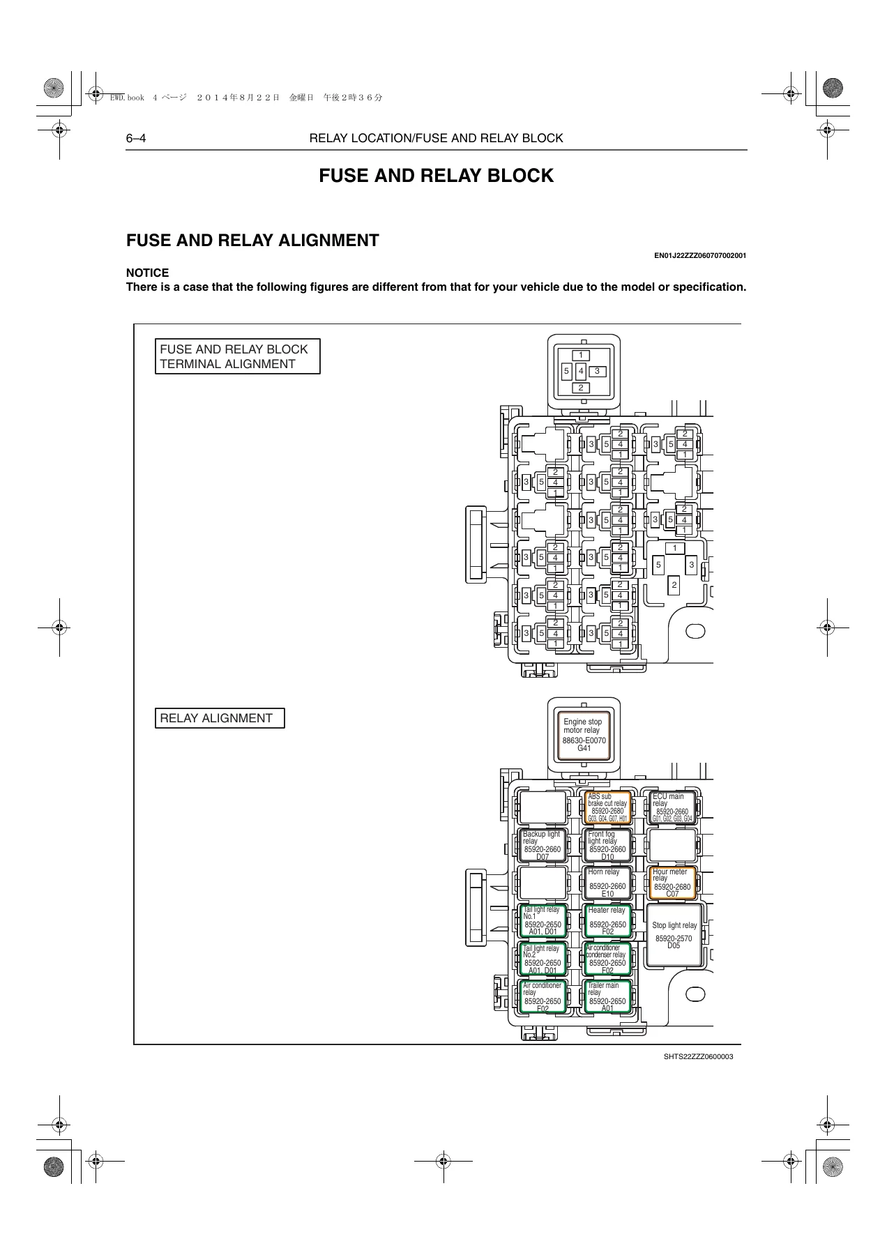
The fuse and relay block section shows terminal alignment for the block itself, then a separate relay alignment view naming each relay – ECU main, engine stop motor, stop light, horn, heater, air conditioner condenser, front fog light, backup light, ABS sub brake cut and the power and headlight relay groups – with part numbers and the circuit each one serves. The fusible link block is drawn out with its alignment, listing the fusible link ratings and the alternator link, so circuit protection can be checked against the actual physical layout rather than a generic chart.
What This Manual Lets You Do
With the Hino FG8J, FL8J, FM2P, FM8J and SG8J electrical wiring workshop manual on hand, you can trace a no-start back through the engine starting circuit to the starter relay, neutral switch and range inhibit ECU; follow a charging complaint through the alternator and fusible link to the battery cables; diagnose lighting faults across headlight, turn, stop, tail, fog, working and room circuits; work through power window, power door lock, wiper and washer, horn, cigarette lighter and radio/audio systems; and tackle the engine management side with the common rail circuits for J08E-CR, J08E-NB and P11C engines, including exhaust brake and PTO. ABS, inter-axle differential lock, ES start, M009 transmission control and the CAN communication network are all covered, along with the diagnosis monitor and 16-pin diagnosis connector circuits so fault codes and live data can be approached with the correct pinout in hand.
Electrical faults are rarely fixed by swapping parts. They are fixed by knowing which wire feeds which pin, where that wire runs, what protects it, and what it connects to at the other end. That is exactly the information this manual provides, in the manufacturer’s own notation, for these specific chassis and engine combinations.
Delivery
The manual is supplied as a PDF file, delivered instantly after checkout – no shipping, no waiting on a physical book. It opens on any device with a PDF reader, from a laptop in the workshop office to a tablet or phone at the vehicle, and any page can be printed for use on the job. Keep it on the shop computer, load it onto a diagnostic tablet, or print the circuit pages you need for the fault in front of you.
IMAGES PREVIEW
Reviews
There are no reviews yet.