
Hino FR1E FS1E FY1E SH1E SR1E SS1E Electrical Wiring Workshop Manual
Original price was: $29.95.$17.95Current price is: $17.95.
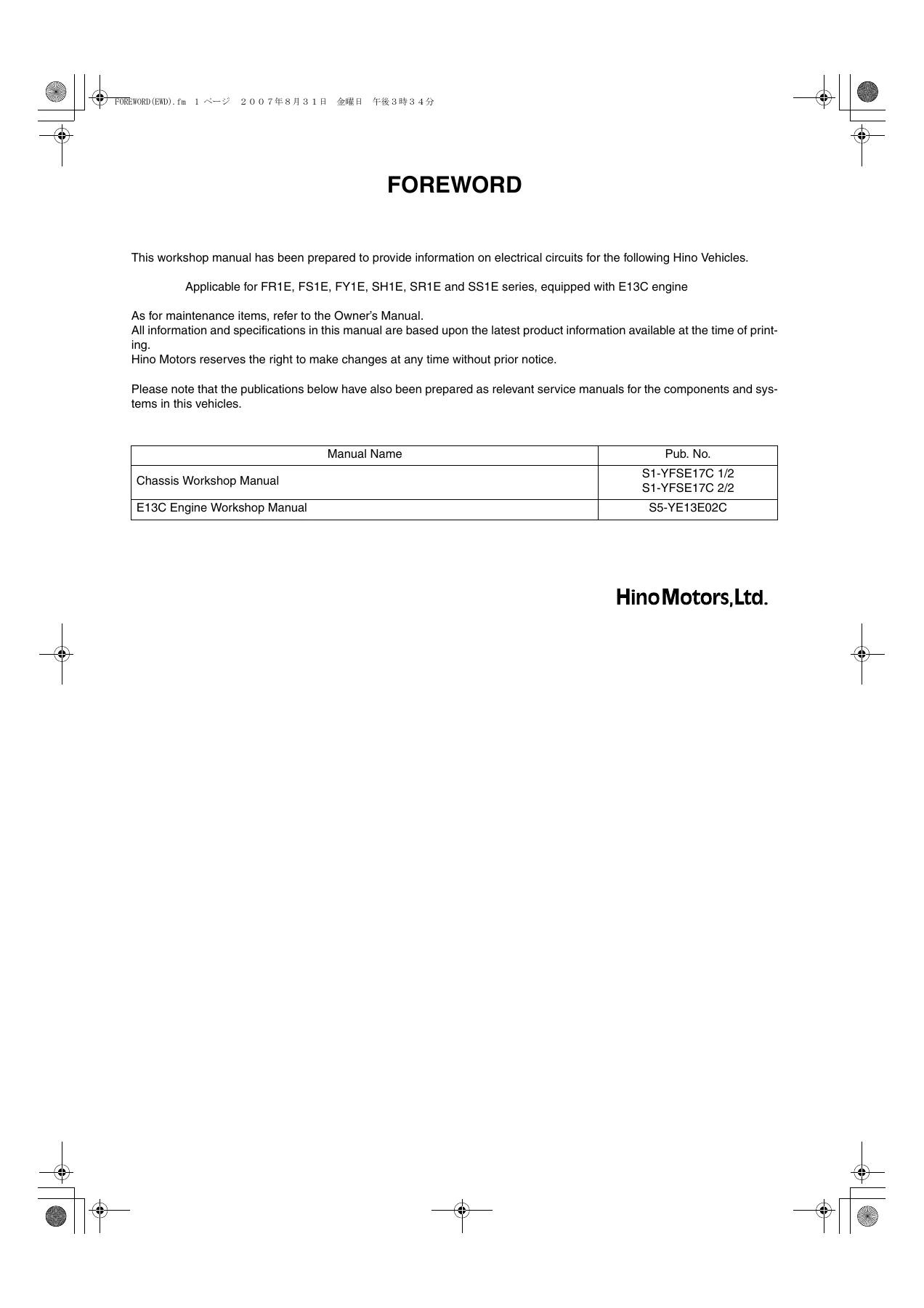
Electrical wiring workshop manual for Hino FR1E, FS1E, FY1E, SH1E, SR1E and SS1E series trucks equipped with the E13C engine, covering circuit diagrams, connector locations, junction connectors, fuse and relay blocks, wire-to-wire connectors and full system-by-system wiring schematics.
Description
Hino FR1E FS1E FY1E SH1E SR1E SS1E Electrical Wiring Workshop Manual
This Hino electrical wiring workshop manual covers the FR1E, FS1E, FY1E, SH1E, SR1E and SS1E series trucks built with the E13C engine. It is a dedicated circuit-and-connector reference: every wiring diagram, harness code, connector code, junction connector and fuse/relay layout the technician needs to read, trace, test or repair the electrical system on these trucks. Where the Chassis Workshop Manual (Pub. No. S1-YFSE17C 1/2 and 2/2) and the E13C Engine Workshop Manual (Pub. No. S5-YE13E02C) cover mechanical work, this Hino FR1E FS1E FY1E SH1E SR1E SS1E Electrical Wiring Workshop Manual is the volume that makes sense of the harness.
File Details
- Manual type: Electrical Wiring Workshop Manual
- Brand: Hino Motors, Ltd.
- Models covered: FR1E, FS1E, FY1E, SH1E, SR1E, SS1E series
- Engine coverage: E13C
- Language: English
- File format: PDF
- Publication number: S1-YFSE17A EWD ’07-3, S1-YFSE17B EWD ’07-6, S1-YFSE17C EWD ’07-9
- Companion manuals referenced: Chassis Workshop Manual S1-YFSE17C 1/2 and 2/2; E13C Engine Workshop Manual S5-YE13E02C
How the Wiring Information Is Organised
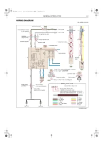
The opening section teaches the notation before the truck is touched. The wiring diagram example identifies part numbers, connector codes, serial numbers in the circuit diagram, terminal numbers, terminal codes, male-side and female-side connector codes, harness-side codes (“a” wiring harness side and “b” wiring harness side), shielded cable and twisted-pair cable callouts, and the wiring colour code key (ground wire colour, stripe colour, and cross-sectional area shown in mm²). Once that notation is understood, every diagram in the book is readable.
Wire-to-wire connector pages then show how the cab main wiring harness, front RH wiring harness, front LH wiring harness, engine wiring harness and the various sub-harnesses join. Each entry states the connector code, harness names, part number, male/female classification and connector colour. Junction connector pages do the same for the internal junction points, with terminal numbering and internal wire connection drawings. The fuse and relay block section covers terminal alignment, relay alignment, relay names and part numbers.
Chapters Covered
The circuit index is split into lettered groups; each group is a self-contained electrical system with its own diagrams, connector references and page numbers.
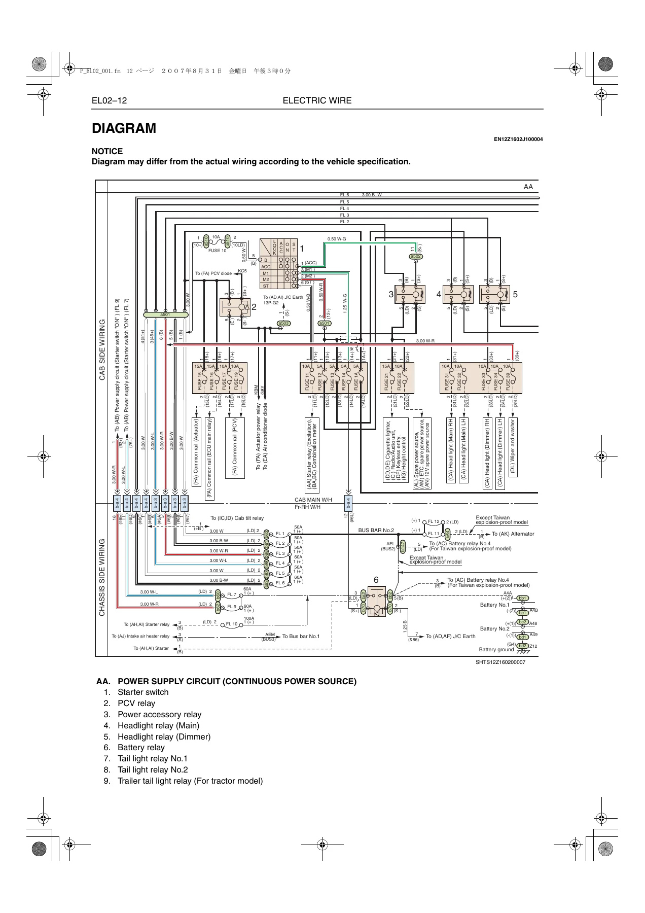
- AA – Power supply circuit (continuous power source)
- AB – Power supply circuit (starter switch “ON”)
- AC – Battery cut switch circuit (for Taiwan explosion-proof model)
- AD – Ground circuit
- AE – Earth system (G2) (cab side)
- AF – Earth system (G2) (chassis)
- AG – Earth system (G4-C and G4-P)
- AH – Engine starting circuit (models with MZ and HX transmission)
- AI – Engine starting circuit (models with ZF and EATON transmission)
- AJ – Engine starting assist circuit
- AK – Charging circuit
- AL – Spare power source circuit
- AM – ETC. spare power source circuit (doubles as 12V spare power source)
- AN – 12V spare power source circuit
- BA – Meter circuit (except semi-tractor) (cab side)
- BB – Meter circuit (except semi-tractor) (chassis side)
- BC – Meter circuit (for semi-tractor) (cab side)
- BD – Meter circuit (for semi-tractor) (chassis side)
- BE – Tachograph circuit
- BF – KIENZLE tachograph circuit
- BG – Fuel filter warning circuit
- BH – Oil filter warning circuit
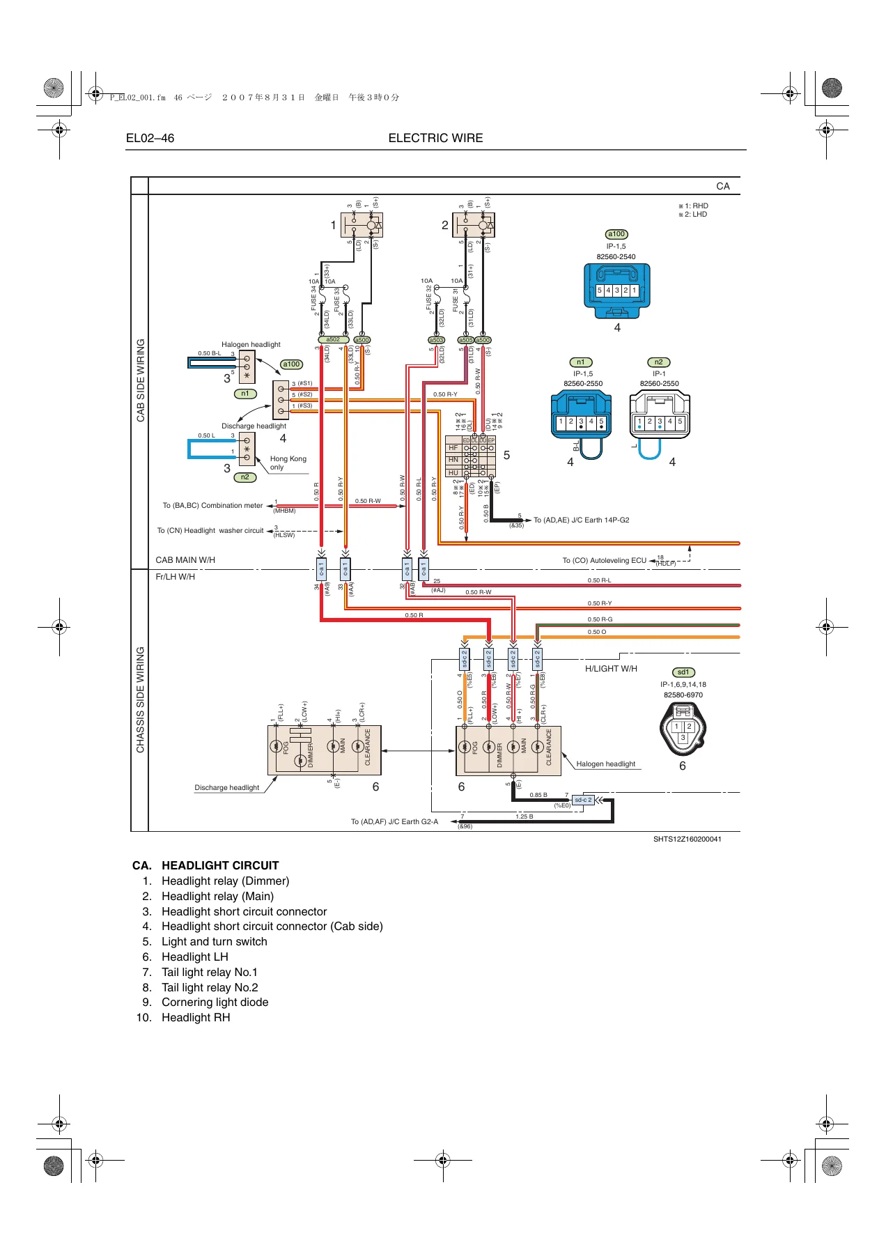
- CA – Headlight circuit
- CB – Headlight beam control circuit
- CC – Turn, stop and tail light circuit (except semi-tractor) (cab side)
- CD – Turn, stop and tail light circuit (except semi-tractor) (chassis side)
- CE – Turn, stop and tail light circuit (for semi-tractor)
- CF – Fog light circuit
- CG – Marker light circuit
- CH – Back-up light circuit (except semi-tractor) (INT-W/H and Rr-W/H integrated type)
- CI – Back-up light circuit (except semi-tractor) (INT-W/H and Rr-W/H divided type)
- CJ – Back-up light circuit (for semi-tractor) (with HX, MZ transmission)
- CK – Back-up light circuit (for semi-tractor) (with ZF transmission)
- CL – Room light circuit
- CM – Working light circuit
- CN – Headlight washer circuit
- CO – Headlight autoleveling circuit
- DA – Mirror heater circuit
- DB – Remote control mirror circuit
- DC – Horn circuit
- DD – Cigarette lighter circuit (for right-hand drive model)
- DE – Cigarette lighter circuit (for left-hand drive model)
- DF – Keyless entry circuit
- DG – Power window circuit (for right-hand drive model)
- DH – Power window circuit (for left-hand drive model)
- DI – Radio/audio circuit
- DJ – Diagnosis connector (16P) circuit
- DK – Diagnosis monitor circuit
- DL – Wiper and washer circuit
- DM – Power door lock circuit
- DN – Power mirror circuit
- EA – Air conditioner circuit
- FA – Common rail circuit No.1 (cab side)
- FB – Common rail circuit No.1 (chassis side)
- FC – Common rail circuit No.2 (EGR and VGT)
- FD – Common rail circuit No.3 (ABS)
- FE – Common rail circuit No.9 (engine retarder)
- FF – Common rail circuit No.11 (speed limiter)
- FG – Common rail circuit No.13 (auto cruise)
- FH – Common rail circuit No.14 (starting idle up control)
- FI – Common rail circuit No.15 (P.T.O.)
- FJ – Common rail circuit No.17 (ETC.)
- GA – ABS circuit (except semi-tractor) (except Australia and New Zealand models)
- GB – ABS circuit (except semi-tractor) (for Australia and New Zealand models)
- GC – ABS circuit (for semi-tractor)
- GD – ES start circuit
- HA – ZF transmission circuit
- HB – MZ transmission circuit
- IA – Cab tilt warning circuit (models with HX and MZ transmission)
- IB – Cab tilt warning circuit (models with ZF and EATON transmission)
- IC – Cab tilt circuit (models with HX and MZ transmission)
- ID – Cab tilt circuit (models with ZF and EATON transmission)
- IE – P.T.O. (power take-off) control circuit
- IF – Air suspension circuit (for semi-tractor)
- IG – Air suspension circuit (for Taiwan FR model)
- IH – Cab suspension circuit
- IJ – Coupler lock circuit
- IK – Inter-axle differential lock circuit
- IL – Rear-rear axle differential lock circuit
- IM – Air dryer circuit
Beyond the circuit diagrams themselves, this Hino electrical wiring workshop manual supplies the supporting apparatus that makes the schematics usable in practice: a wiring harness code table naming the cab main wiring harness, front RH and LH wiring harnesses, intermediate wiring harness, rear wiring harness, instrument panel and instrument panel switch wiring harnesses, dash panel wiring harness, roof wiring harness, door LH and RH wiring harnesses, floor wiring harness, 12V spare power source wiring harness, bonding earth cable, battery cables 1 through 4, engine wiring harness, injector sub wiring harness, link-up connector, ZF transmission sub wiring harness, ZF transmission P.T.O. sub wiring harness, intake air heater sub wiring harness, headlight sub wiring harness, cab tilt sub wiring harness, air suspension valve box sub wiring harness, brake valve box sub wiring harness and side turn signal sub wiring harness.
A connector location section then maps every connector to a physical area on the vehicle – instrument panel (in four parts for right-hand drive and four parts for left-hand drive), cab (right-hand and left-hand drive), engine (three parts for each market: Australia, Hong Kong, Ireland, New Zealand, Taiwan), and rear (leaf suspension, air suspension, full-tractor, semi-tractor and other variants). Each area is further broken down by destination and model so the correct diagram set can be selected before any wire is probed.
What This Manual Enables
With this wiring manual open, a technician can trace a fault from a fuse, through the relay block, along the harness, across a wire-to-wire connector and into the component at the far end. That includes finding intermittent grounds, chasing a shorted stop-light circuit, diagnosing a non-cranking engine-start circuit, isolating an ABS warning, following the common rail ECU wiring, working through the ZF or MZ transmission circuits, and confirming whether a cab tilt or P.T.O. control problem is a switch, a relay, a magnetic valve or a break in the harness.
Electrical work is where guesswork becomes expensive. Substituting the wrong terminal code, misreading a junction connector pinout or confusing a right-hand drive diagram with a left-hand drive diagram can send power into a circuit that was never designed to see it. The correct wiring diagram, the correct harness code and the correct connector location page remove that risk. Because this manual is split by destination and model, the buyer can go straight to the exact diagram set for the truck in front of them rather than trying to adapt a generic diagram.
IMAGES PREVIEW
Delivery is by instant PDF download after checkout – no shipping, no waiting. The file can be opened on a workshop laptop, a tablet on the cab floor or a phone next to the harness, and specific pages can be printed and taken into the truck. Zoom into a connector detail, print the circuit page, mark it up, and keep the original clean.
Reviews
There are no reviews yet.