
Isuzu F-Series Australia Body Builders Guide 2015 – FRR FSR FTR FVR FVM FVZ FSS FTS Cab Chassis Modification Manual
Original price was: $34.95.$21.95Current price is: $21.95.
July 2015 Isuzu F-Series Body Builders Guide for Australia covering FRR, FSR, FTR, FVR, FVM, FVZ, FSS and FTS cab-chassis models. Chassis modification rules, rear body mounting, sub frames, frame section modulus, PTO, electrical system, painting, cab-chassis drawings and ADR compliance guidance for the 2015 sales model year.
Description
Isuzu F-Series Body Builders Guide 2015 for Australia
This is the July 2015 Isuzu F-Series Body Builders Guide issued by Isuzu Motors Limited for the Australian market. It is the working document body builders use when mounting a rear body on an Isuzu cab-chassis supplied as a Partially Complete Vehicle (PCV), and it sets out how to do that without compromising the Australian Design Rules compliance, safety, durability or warranty of the finished truck. The guide covers the 2015 sales model year and the full Australian F-Series range: FRR, FSR, FTR, FVR, FVM, FVZ, FSS and FTS.
Because the manual is written for the trade rather than the driver, it goes straight into the technical territory a body builder actually needs: where you may and may not drill or weld a chassis frame, how to reinforce a side member, how to extend a rear overhang, what clearances to keep around the engine, transmission, propeller shafts, exhaust and cab, how to size a sub frame, and how to fix the rear body with U-bolts or double-ended brackets. It is the reference you reach for before cutting into a brand-new Isuzu chassis.
File Details
- Manual type: Body Builders Guide / chassis modification and rear body mounting reference
- Brand: Isuzu Motors Limited
- Vehicle family: Isuzu F-Series for Australia (2015 sales model year)
- Publication date: July 2015
- Language: English
- Conformity reference: Australian Design Rules for Road Vehicles
- Format: PDF (instant download)
- Length: approx. 400 pages across two main parts, plus drawings and appendix
Models Covered
The guide is organised around the Australian F-Series line-up and provides vehicle-specific data for each variant. Model names appear throughout in both Isuzu Japan format and the IAL format used locally.
- FRR series: FRR90SU-JAHS, FRR90SU-KAHS, FRR90SU-MAHS, FRR90SU-QAHS, FRR90TU-QAHS, FRR90SU-PVHS, FRR34SU-LCHN, FRR34SU-LCHN-P, FRR34SU-PCHN, FRR34SU-PCHN-P, FRR34SU-PVHN, FRR34SU-QCHN, FRR34TU-LCHC, FRR34TU-PCHC, FRR34TU-PCHC-P (FRR500 / FRR600 / FRD500 / FRD600 variants)
- FSR series: FSR34SU-JCHN-P, FSR34SU-QCHN, FSR34SU-QCHN-P, FSR34SU-UCHN, FSR34TU-QCHC, FSR34TU-QCHC-P (FSR700 / FSR850 / FSD700 / FSD850)
- FTR series: FTR34UU-LDHC, FTR34UU-SDHC, FTR34UU-TDHC, FTR34UU-SYHC (FTR900)
- FVR series: FVR34UU-LDHS, FVR34UU-QDHS-P, FVR34UU-TDHS, FVR34UU-QDHS-P, FVR34UU-TDHS, FVR34UU-TDHS-P (FVR1000 / FVD1000)
- FVM series: FVM34UU-WDHS, FVM34VU-WDHS, FVM34VU-WDHS-P (FVM1400 / FVL1400)
- FVZ series: FVZ34UU-PDHS, FVZ34UU-PDHS-P, FVZ34UU-SDHS-P, FVZ34UU-WDHS, FVZ34VU-PDHS-P, FVZ34VU-WDHS, FVZ34VU-WDHS-P (FVZ1400 / FVY1400)
- FSS series: FSS90SU-JCHS, FSS90SU-LVHS (FSS550 4×4)
- FTS series: FTS34SU-LDHN, FTS34SU-LDHN-P, FTS34SU-LYHN, FTS34SU-LYHN-P (FTS800 4×4)
Engines Referenced
- 4HK1-TCS – 5,193 cc, EURO V, 151 kW / 2,600 rpm, 637 Nm / 1,600 rpm
- 4HK1-TC – 5,193 cc (FSS / FTS 4×4 applications)
- 6HK1-TCN – 7,790 cc, EURO V, 176 kW / 2,400 rpm, 706 Nm / 1,450 rpm
- 6HK1-TCC – 7,790 cc, EURO V, 191 kW / 2,400 rpm, 760 Nm / 1,450 rpm
- 6HK1-TCS – 7,790 cc, EURO V, 221 kW / 2,400 rpm, 980 Nm / 1,450 rpm
Chapters Covered
Part I – General Precautions
- Chapter 1 – General
- Precautions for installing body: body weight, cab, chassis maintenance access, other
- Precautions at installing: preparation, work, starting up engine, moving the vehicle
- Precautions for bolt tightening
- Chapter 2 – Modification of Chassis
- Drilling or welding a chassis frame (side member, cross member, gusset, other cautions)
- Reinforcing a chassis frame side member (material, installation, rivet size)
- Modifying rear overhang of a chassis frame (extension material and installation)
- Precautions for welding (before welding, after welding, welding electrode)
- Precautions for hydraulic or air piping (working efficiency, pipe forming, routing steel pipes)
- Nylon air tubes and push-in connectors
- Nylon tube routing and fixing
- Relocation or addition of a fuel tank
- Precautions for towing hook
- Precautions for modification of the electrical system
- Engine output characteristic (PTO work output) and the control
- Precautions for painting, emblems, decals
- Chapter 3 – Rear Body Mounting
- Consideration to proper load
- Clearance between equipment or component on cab-chassis and rear body
- Sub frame side members (front end shape, measure against sub frame, front end position)
- Fixing of a rear body: location and pitch of bolts, attachment prohibited areas, U-bolts, double-ended brackets, anti-shift/anti-slide devices
Part II – Specific Information
- Chapter 1 – Outline: ID plate, ID code components, VIN, vehicle number and engine model number locations, vehicle model code chart
- Chapter 2 – Principal Specifications of Various Vehicle Models: twelve-page specification tables for the full FRR / FSR / FTR / FVR / FVM / FVZ / FSS / FTS range
- Chapter 3 – Precautions for Rear Body Mounting: SRS airbag, DPD, HSA, ABS/ASR, AMT, roof equipment, through holes for harnesses and antenna cable, side turn signal lamp handling
- Chapter 4 – Curb Weight Data and Frame Strength Calculation: curb weight and axle capacity, weight distribution formulas, frame section modulus diagrams
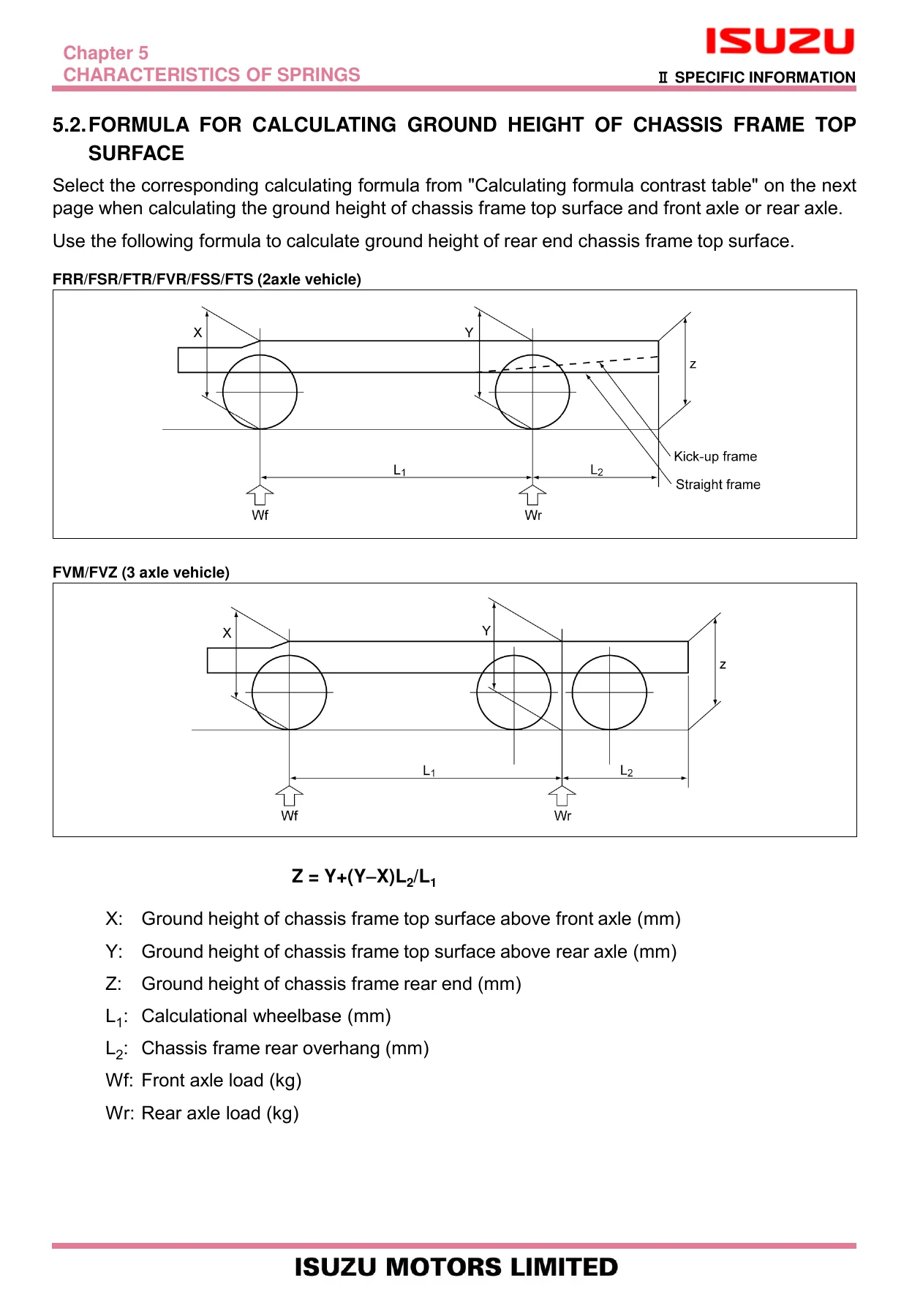
- Chapter 5 – Characteristics of Springs: spring specifications by model, formula for calculating ground height of chassis frame top surface, margin for movement of the rear axle and tires
- Chapter 6 – PTO and Governor Characteristics Curves: PTO variation, transmission side PTO, flywheel PTO, transmission rear PTO, PTO control, AMT, governor characteristics curves
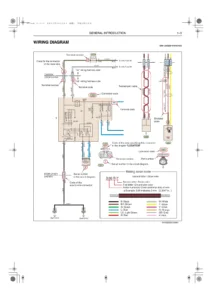
- Chapter 7 – Electrical System: lamp adjustment, AC generator output, fuses, relays, service terminals, side turn signal lamps, circuit diagram symbols and abbreviations
- Chapter 8 – Painting: cab painting, paint boundary, limit temperature of resin components, painting-prohibited areas
- Chapter 9 – Cab Chassis Drawings: cab-chassis drawings and cab back detail drawings for every Australian model
- Chapter 10 – Chassis Frame Drawings: chassis frame drawings and detailed cross member drawings
- Chapter 11 – Location of Various Components: air tank and air equipment, fuel tank, battery and carrier, spare tire and carrier
- Chapter 12 – Appendix: piping diagrams and location of decals
What This Guide Actually Gives You
This is not a generic workshop manual, and it is not a sales brochure. It is the engineering interface document between Isuzu and the body building trade. Every restriction in it exists because someone, at some point, cracked a chassis rail, cooked a wiring loom, or set a truck on fire by doing it wrong. The drilling and welding rules alone – flange prohibition, allowable maximum hole diameter by duty class, minimum distance from holes, weld length and spacing, cold rivet only – will save a fabricator from turning a $200,000 cab-chassis into a warranty claim. The sub frame chapter explains how the sub frame front end should be shaped and positioned so the load path does not concentrate stress just behind the second cross member, which is exactly where a badly built truck fails.
Beyond the mechanical side, the guide walks you through relocating or adding a fuel tank under Australian regulation, routing nylon air tube and steel hydraulic pipe without introducing freeze points or chafe, sizing electrical wire and fuses correctly, and modifying the electrical system without disabling the ABS, ASR, AMT, HSA or SRS airbag systems. It also contains the ADR compliance checklist for lighting, reflectors, mudguards and the rear registration plate – the items the body builder, not Isuzu, is responsible for on a PCV.
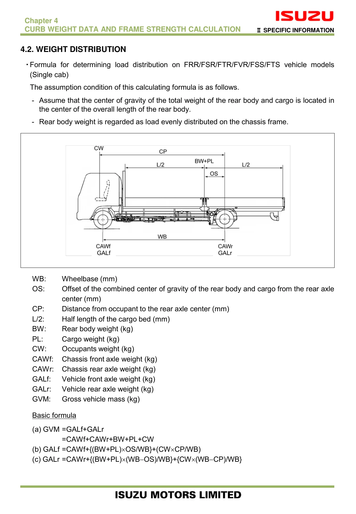
The second half is where the vehicle-specific value sits. Principal specification tables list GVM, GCM, axle capacity, wheelbase, tread, steering angle, engine output and torque, transmission, final drive ratio, tyre and disc wheel, brake system, air tank capacity, suspension leaf span, fuel tank capacity, silencer, DPD, ACG, battery and starter output for every single model. Frame section modulus diagrams give the actual strength distribution along each chassis rail so you can calculate where a body or sub frame may load the frame without exceeding the permissible stress, and the weight distribution formulas let you compute front and rear axle loads from body weight, cargo weight, wheelbase and rear overhang.
For Whom This Guide Is Written
Body builders, transport engineers, fleet workshops, and truck modifiers working on Isuzu F-Series cab-chassis in Australia. It is equally useful to anyone speccing a new body, checking whether a planned modification is permitted before cutting metal, or trying to understand why Isuzu says a particular area of the frame is off limits. Because it covers the full 2015 Australian F-Series range in one document, it lets a workshop work across FRR, FSR, FTR, FVR, FVM, FVZ, FSS and FTS without chasing separate guides.
Why It Matters
Get the frame modification wrong and the failure usually shows up later, at the worst possible time, on a loaded truck. Get the electrical modification wrong and the first symptom may be an airbag fault or an ABS warning. Get the rear body mounting wrong and the truck will not pass the ADR compliance the body builder is legally responsible for. This guide exists to make sure the completed vehicle is safe, durable, compliant and warranty-intact – and it is the same document Isuzu Australia refers to when a dispute arises.
IMAGES PREVIEW
Instant PDF Delivery
This Isuzu F-Series Body Builders Guide is delivered as an instant PDF download. No shipping, no waiting, no physical binder to misplace in the workshop. Once payment is complete you can open it on any device – laptop in the office, tablet on the workshop floor, or printed out chapter by chapter. That means you can have the drilling and welding rules on the bench next to the chassis, the frame section modulus diagram open on screen, and the ADR compliance checklist in hand while you are still standing at the truck.
Reviews
There are no reviews yet.