
Hino Truck Electrical Wiring Diagrams Manual – J08E & A09C Engines Complete System Schematics
Original price was: $39.95.$24.95Current price is: $24.95.
Complete 169-page Hino electrical wiring diagram manual covering power supply, starting, charging, lighting, ABS, common rail, VCS, UREA SCR, and every major truck system for J08E and A09C engine models.
Description
File Details
- Manual Type: Electrical Wiring Diagrams According to System
- Brand: Hino
- Models Covered: Hino trucks equipped with J08E and A09C engines; MX06, M009, EATON, and ALLISON 3000 transmissions; Single Cab and Crew Cab variants
- Language: English
- Page Count: 169
- File Format: PDF
- Document Number: EN01J22ZZZ020707001001 (and related system drawing numbers)
- Update Date: 2023-04-20
- Print Date: 2024-01-22
Chapters Covered
This Hino electrical wiring diagrams manual is organized by vehicle system, giving technicians a direct path to the exact circuit they need to diagnose or repair. The contents include:
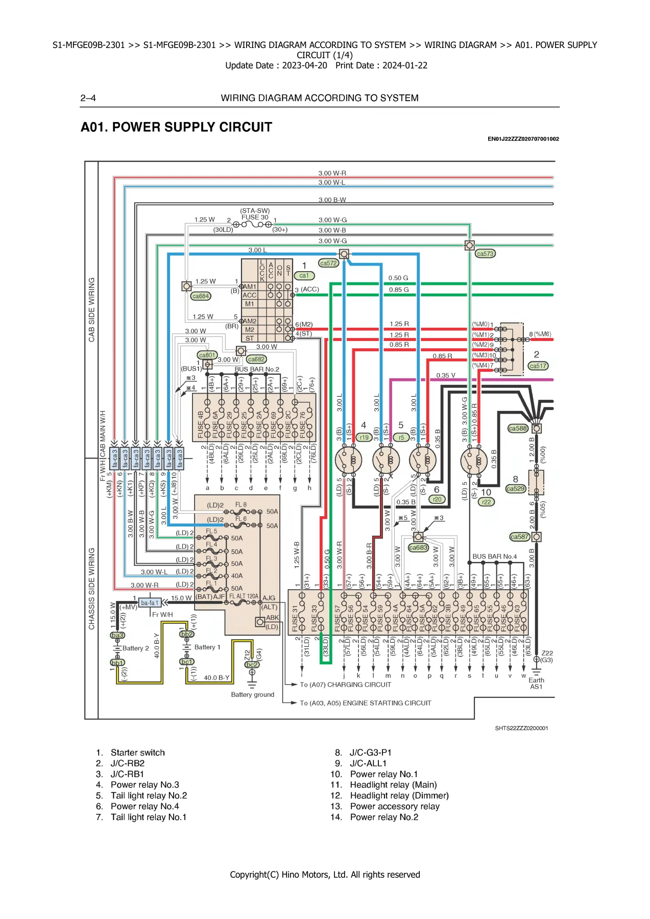
- A01. Power Supply Circuit
- A03. Engine Starting Circuit (MT)
- A05. Engine Starting Circuit (ALLISON)
- A07. Charging Circuit
- A08. ETC. Spare Power Supply Circuit
- B01. Ground Circuit No.1 (1 of 2)
- B02. Ground Circuit No.1 (2 of 2)
- B03. Ground Circuit No.2
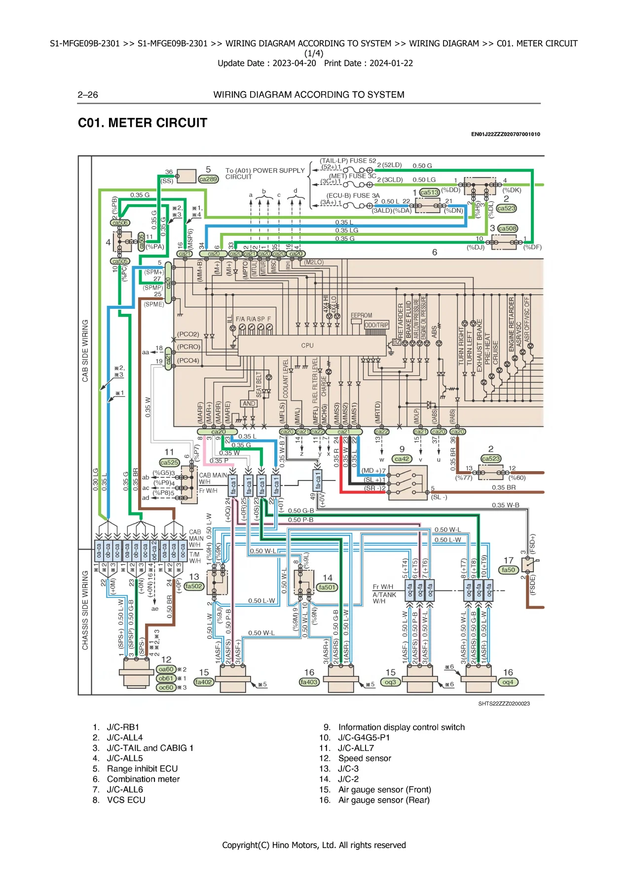
- C01. Meter Circuit
- C08. Coolant Level Warning Circuit
- D01. Headlight Circuit
- D03. Headlight Beam Control Circuit (1 of 2)
- D04. Headlight Beam Control Circuit (2 of 2)
- D06. Tail Light Circuit
- D07. Backup Light Circuit (MT)
- D08. Backup Light Circuit (AT)
- D10. Fog Light Circuit
- D12. Room Light Circuit
- E01. Integrated Unit Circuit No.1 (1 of 2)
- E02. Integrated Unit Circuit No.1 (2 of 2)
- E03. Integrated Unit Circuit No.2
- E04. Headlight Washer Circuit
- E05. Remote Control Mirror and Mirror Heater Circuit
- E06. Cigarette Lighter Circuit
- E07. Radio/Audio Circuit
- E08. Keyless Entry Circuit
- E09. Airbag Circuit
- E10. Horn Circuit
- E11. Power Window Circuit
- F01. Air Conditioner Circuit
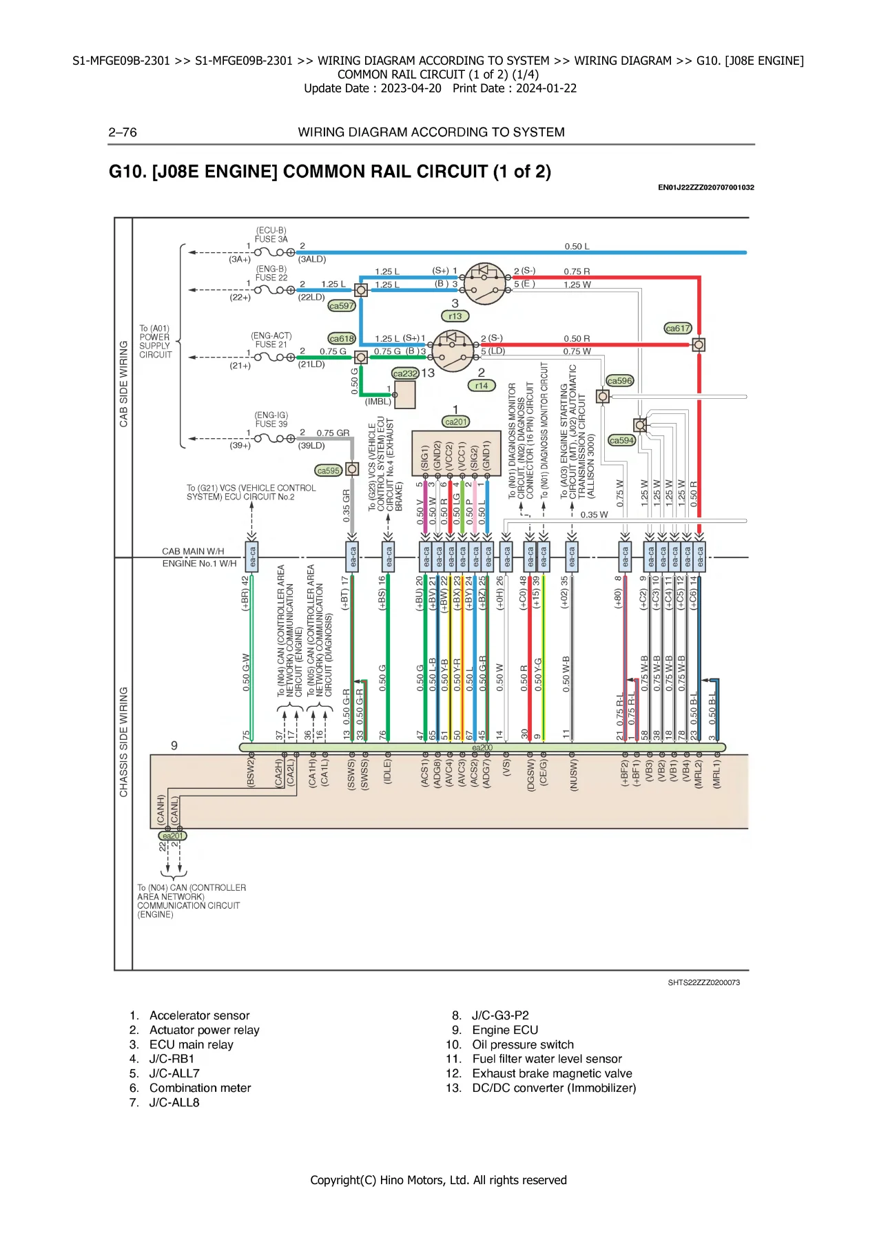
- G10. [J08E Engine] Common Rail Circuit (1 of 2)
- G11. [J08E Engine] Common Rail Circuit (2 of 2)
- G14. [J08E Engine] Common Rail Circuit (PTO)
- G20. VCS (Vehicle Control System) ECU Circuit No.1
- G21. VCS ECU Circuit No.2
- G22. VCS ECU Circuit No.3 (Cruise)
- G23. VCS ECU Circuit No.4 (Exhaust Brake)
- G24. VCS ECU Circuit No.5 (Start Stop)
- G35. [A09C Engine] Common Rail Circuit (1 of 2)
- G36. [A09C Engine] Common Rail Circuit (2 of 2)
- G37. [A09C Engine] Common Rail Circuit (PTO)
- G38. [A09C Engine] Common Rail Circuit (Exhaust Brake)
- G40. Immobilizer Circuit
- G60. UREA SCR Circuit
- H01. ABS Circuit (1 of 2)
- H02. ABS Circuit (2 of 2) (With VSC)
- H03. Differential Lock Circuit
- H04. Electromagnetic Retarder Circuit
- H09. ES Start Circuit
- J01. Transmission Control Circuit (M009)
- J02. Automatic Transmission Circuit (1 of 2) (ALLISON 3000)
- J03. Automatic Transmission Circuit (2 of 2) (ALLISON 3000)
- J05. Low-Hi Indicator Light Circuit (EATON)
- K01. Cab Tilt Circuit (Single Cab)
- K02. Cab Tilt Circuit (Crew Cab)
- L01. Transmission PTO Control Circuit (MX06, M009)
- L02. Transmission PTO Control Circuit (EATON)
- L06. Transmission PTO Control Circuit (ALLISON)
- M01. Air Dryer Circuit
- M02. Height Control Circuit
- N01. Diagnosis Monitor Circuit
- N02. Diagnosis Connector (16 Pin) Circuit
- N03. CAN Communication Circuit (Vehicle)
- N04. CAN Communication Circuit (Engine)
- N05. CAN Communication Circuit (Diagnosis)
Each circuit section presents a complete wiring diagram with connector callouts, pin numbers, wire colors, wire gauges, relay locations, fuse references, ground points, and junction connector identifiers. The manual also includes dedicated connector illustration pages that show the physical shape, pin layout, and terminal arrangement for every connector referenced in the diagrams, making it possible to identify and test connectors directly at the vehicle. Wiring harness codes are provided at the front so you can map any harness abbreviation to its location and function.
What This Manual Enables
This Hino electrical wiring diagrams manual gives you the complete circuit architecture for trucks built on the J08E and A09C engine platforms. With these diagrams, you can trace any electrical fault from the battery through the fuse box, relays, junction connectors, and ECU pins to the component at the other end. Whether you are chasing a no-start condition on a manual transmission truck, diagnosing a CAN communication fault, testing an ABS modulator circuit, or repairing a UREA SCR system, the relevant diagram is here.
Each system diagram shows the exact wire color codes, connector codes, pin numbers, and splice points. The connector illustrations that follow the diagrams let you match the physical connector on the truck to the schematic, so you can probe the correct terminal without guessing. Relay and fuse locations are identified, and the power supply and ground circuit sections give you the foundation needed to verify voltage and continuity across the entire vehicle.
Coverage for Multiple Configurations
The manual accounts for the major drivetrain and body variants. Separate starting circuit diagrams are provided for manual transmission and ALLISON automatic transmission models. Backup light circuits differ for MT and AT. Transmission control sections cover the MX06, M009, EATON, and ALLISON 3000 units. Cab tilt circuits are split between Single Cab and Crew Cab. Engine common rail circuits are documented for both the J08E and A09C engines, including PTO and exhaust brake variants. ABS is covered with and without VSC.
This level of configuration detail means you can use one manual across a fleet with mixed specifications and still find the correct diagram for each truck. The notice at the front acknowledges that circuit diagrams may differ by model or specification, and the multiple variants included in the manual exist precisely to address those differences.
Why This Manual Matters for Diagnostics
Electrical faults on modern trucks can originate anywhere from a corroded ground point to a failed sensor, a chafed wire, a faulty relay, or a CAN bus communication error. Without a wiring diagram, troubleshooting becomes a process of trial and error that costs time and parts. This manual removes the guesswork. You can identify the exact circuit, locate the connectors and grounds, and test the correct pins with a multimeter. For intermittent faults, having the connector views and wire routing lets you inspect the known problem areas instead of tearing apart the entire harness.
The diagnosis sections (N01, N02, N03, N04, N05) are especially useful when a fault code points to a communication problem. These diagrams show how the diagnostic connector, ECUs, and CAN buses are wired together, so you can determine whether the issue is a shorted bus line, a failed terminator, or a faulty ECU.
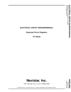
IMAGES PREVIEW
Instant PDF Delivery
This Hino electrical wiring diagrams manual is delivered as an instant PDF download. There is no shipping, no waiting for a physical book, and no risk of a damaged or lost package. The file opens on any device that supports PDF viewing, including laptops, tablets, and smartphones. You can print individual diagram pages for use in the workshop, or keep the entire manual on a tablet for quick reference at the vehicle. The PDF format preserves the original page layout, so connector illustrations and wiring diagrams appear exactly as intended. Whether you are a professional technician, a fleet maintenance manager, or an owner doing your own repairs, this manual gives you the information needed to diagnose and repair Hino electrical systems correctly.

Reviews
There are no reviews yet.