
Hitachi 350LC-5B 350LCN-5B Hydraulic Excavator Technical Manual – Operational Performance Test & Troubleshooting PDF
Original price was: $39.95.$24.95Current price is: $24.95.
Complete Hitachi Technical Manual for the 350LC-5B and 350LCN-5B hydraulic excavators, covering operational performance testing, standard values, engine and machine tests, component tests, adjustment procedures and full fault-code / symptom-based troubleshooting. 508-page instant PDF download.
Description
Hitachi 350LC-5B / 350LCN-5B Hydraulic Excavator Technical Manual
This is the factory-issued Technical Manual (document number TTDDD-EN-01, dated 20250626) for the 350LC-5B and 350LCN-5B hydraulic excavators built by Hitachi Construction Machinery. It is the volume a technician reaches for when a machine has to be measured, benchmarked, diagnosed and brought back to specification — not a generic guide, but the same performance-test and troubleshooting content used in the workshop.
Across 508 pages the manual walks through every standard value you need for a healthy 350LC-5B or 350LCN-5B, then drills into the diagnostic tree for each subsystem: engine, pumps, control valve, swing, travel, attachment hydraulics and the air conditioner. Everything is written for the experienced technician, so expect dense specification tables, P-Q diagrams, monitor / MPDr. reference values and step-by-step inspection procedures rather than simplified overviews.
File Details
- Manual type: Technical Manual (Operational Performance Test & Troubleshooting)
- Brand: Hitachi Construction Machinery
- Models covered: 350LC-5B, 350LCN-5B
- Document number: TTDDD-EN-01
- Edition / date: 20250626
- Language: English
- Page count: 508 pages
- File format: PDF (instant download)
Chapters Covered
- To The Reader — how the manual is organised, page-numbering conventions, unit conversions, symbol / abbreviation glossary (MC, ECM, VGS, DPF, DPD, DOC, CSF, EGR and more)
- Safety Chapter — Recognize Safety Information, Understand Signal Words (DANGER / WARNING / CAUTION / IMPORTANT / NOTE), Follow Safety Instructions, Prepare for Emergencies, Wear Protective Clothing, Protect Against Noise, Inspect Machine, General Precautions for Cab, Use Handholds and Steps, Adjust the Operator’s Seat, Fasten Your Seat Belt, Move and Operate Machine Safely, Operate Only from Operator’s Seat, Jump Starting, Keep Riders off Machine, Precautions for Operations, Investigate Job Site, Install OPG Guard, Signals for Multiple Machines, Drive Machine Safely, Rollaway Accidents, Back-Over and Swing Accidents, Keep Person Clear, Avoid Undercutting, Avoid Tipping, Never Undercut a High Bank, Dig with Caution, Avoid Power Lines, Object Handling, Protect Against Flying Debris, Park Machine Safely, Handle Fluids Safely, Service Machine Safely, Support Machine Properly, Stay Clear of Moving Parts, Prevent Parts from Flying, Prevent Burns, Replace Rubber Hoses, Avoid High-Pressure Fluids, Prevent Fires, Evacuating in Case of Fire, Precautions for Welding and Grinding, Accumulator and Gas Dumper Handling, Battery Explosions, Air Conditioning Service, Chemical Handling, Waste Disposal, Muffler Filter Notes, Communication Terminal Precautions
- Section 4 — Operational Performance Test
- Group 1 Introduction — purpose of performance tests, kinds of tests, performance standards, test area, precautions, precise measurement
- Group 2 Standard — operational performance standard table, Main Pump P-Q Diagrams (P1, P2, P3), sensor activating ranges, MPDr. monitor indicating values (ECM / MC / Wiper-Light)
- Group 3 Engine Test — engine speed, lubricant consumption
- Group 4 Machine Performance Test — travel speed, track revolution speed, mistrack check, travel parking leakage, swing speed, swing function drift, swing motor leakage, maximum swingable slant angle, swing bearing play, hydraulic cylinder cycle time, dig function drift, control lever operating force and stroke, combined boom raise / swing, combined boom raise / arm roll-in, clearance of front attachment connecting parts
- Group 5 Component Test — primary pilot pressure, secondary pilot pressure, 5-spool and 2-spool solenoid valve set pressures, main pump delivery pressure, main relief set pressure, swing relief pressure, overload relief valve set pressure, main pump flow rate (P-Q and pilot characteristics), swing motor drainage, travel motor drainage
- Group 6 Adjustment — No-Load-Max differential pressure measurement, muffler filter differential pressure sensor learning, rewrite of muffler filter serial number, muffler filter maintenance
- Section 5 — Troubleshooting
- Group 1 Diagnosing Procedure — electrical system inspection, disconnecting connectors, fuse inspection, fusible link, battery voltage check, alternator check, continuity check, voltage and current measurement, false-signal test, test harnesses
- Group 2 Monitor — service menu operation, Troubleshooting screen, Monitoring screen, Controller Version, Issued Warning Record, Operation hour meters, Communication Terminal Status, Machine Setting, Monitor Setting, Engine Setting, Muffler Filter No.
- Group 3 e-Service — operation data, daily report data, frequency distribution data, total operating hours, snapshot data, communication system
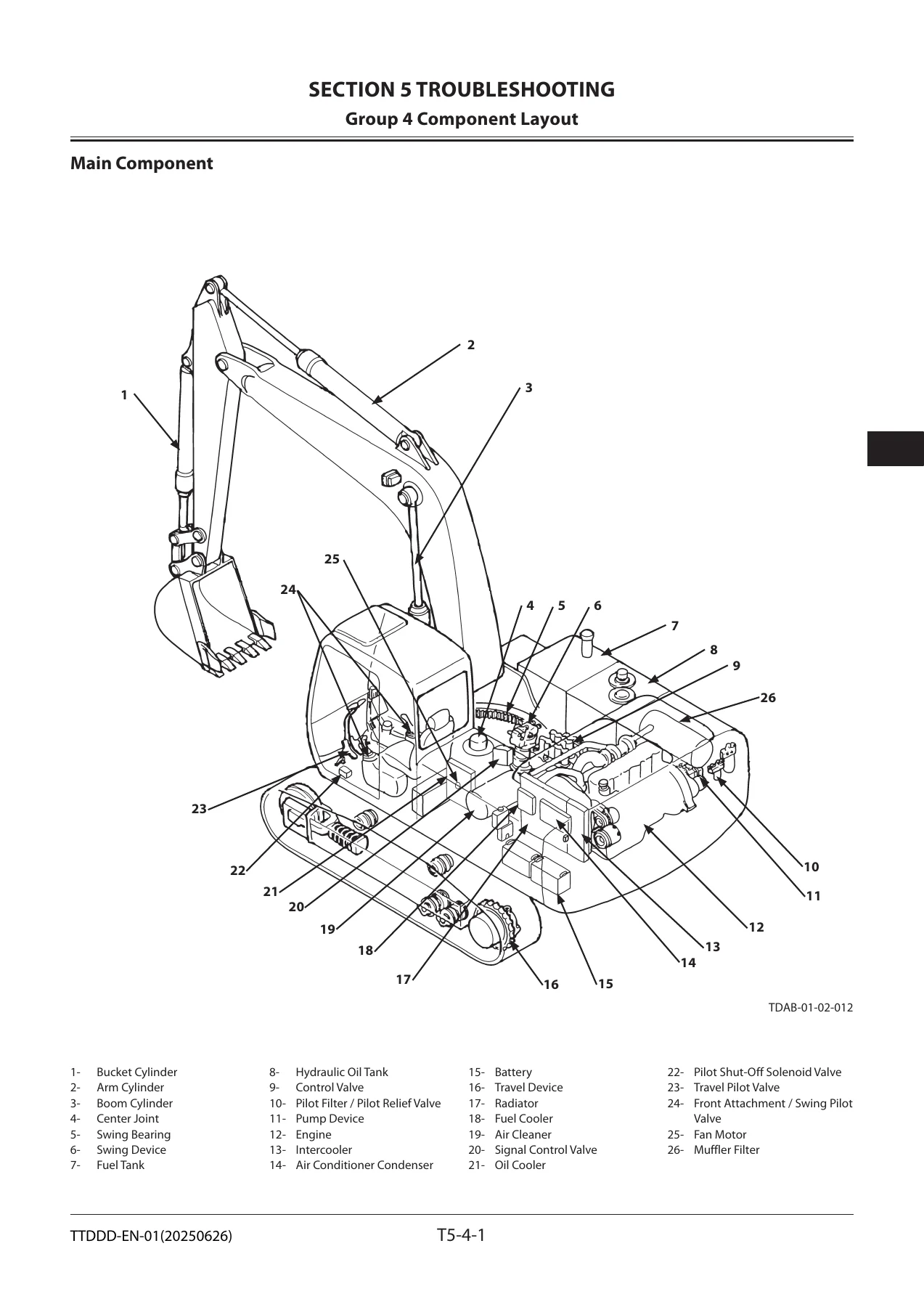
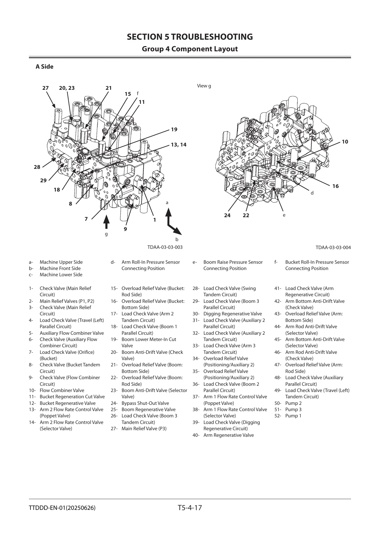
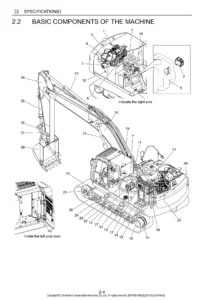
- Group 4 Component Layout — main component layout, front attachment, electrical system (rear tray, switch panel, utility space, relays), engine, muffler filter, pump device, control valve and its internal components, swing and travel device, 5-spool / 2-spool solenoid valve units, pilot port charts
- Group 5 Troubleshooting A (fault codes) — MC fault code list, engine (ECM) fault codes, pump / pilot / proportional solenoid / electrical lever fault codes, Monitor Controller fault codes, Air Conditioner controller fault codes, communication terminal fault codes, and detailed inspection procedures for each code
- Group 6 Troubleshooting B (symptom based) — engine system, all-actuator system, front attachment system, swing system, travel system, other systems (lights, wiper, washer), exchange inspection method, how to lower the boom in an emergency (with and without hose rupture valve), attachment circuit pressure release
- Group 7 Air Conditioner — layout, component layout, functions of main parts, troubleshooting, fault-code list and inspection procedures, work after replacing components, compressor oil refill, charging with refrigerant, hose and pipe tightening torques
- Revision Request Form and Attached Diagram List (electrical circuit diagram, cab / engine / pump / monitor harnesses, GSM and satellite communication harness, key switch harness, pilot shut-off solenoid harness, rear-view camera harness, hydraulic circuit diagrams for mono boom, 2-piece boom, Europe spec and Oceania spec)
Together these groups turn the manual into a full diagnostic toolkit for the 350LC-5B and 350LCN-5B. You get the number you should be seeing on a healthy machine, the number the machine is actually producing, and the exact procedure to close the gap.
What You Can Do With This Manual
With the standard tables in Section 4 you can verify a machine has been delivered, repaired or rebuilt to specification rather than just “running”. Travel speed, mistrack, swing drift, swing bearing play, cylinder cycle times, pilot pressures, relief pressures, pump flow rate along the P-Q curve and motor drainage are all measured against printed limits, so a decision to repair, adjust or replace is supported by data instead of guesswork.
Section 5 is where the manual really earns its place. When a fault code appears on the 350LC-5B or 350LCN-5B you can look it up in Troubleshooting A and follow the exact inspection method — which terminal, which condition, which evaluation, which cause. When no fault code is shown, Troubleshooting B starts from the symptom instead: engine will not start, actuators slow, arm roll-in slow during digging, machine mistracks, swing slow, auto/manual muffler filter regeneration not working, fan speed will not change, wiper or washer dead, and so on, each with the contributing components ranked and a step-by-step inspection ladder.
Why This Matters
Modern 350LC-5B and 350LCN-5B machines are governed by MC and ECM control logic, proportional solenoid valves, pressure sensors and CAN communication. Guessing at a complaint wastes time and risks damaging components that are still within spec. This manual gives you the reference values, the sensor ranges, the MPDr. monitor items and the fault-code branches so you can isolate the real cause on the first pass, then repair or adjust only what actually needs it.
Delivery
IMAGES PREVIEW
Instant PDF download after payment — no shipping, no waiting. Read it on a laptop, tablet or phone in the cab, or print the pages you need for the workshop bench. The entire 508-page Hitachi 350LC-5B / 350LCN-5B Technical Manual is in a single search-friendly file.

Reviews
There are no reviews yet.