
Hitachi EX75UR-5 EX75US-5 Excavator Technical Manual & Wiring Diagrams – TT197E
Original price was: $39.95.$23.95Current price is: $23.95.
Complete Hitachi Technical Manual (Troubleshooting) for the EX75UR-5 and EX75US-5 excavators – operational performance tests, fault-code diagnostics, hydraulic and electrical circuit diagrams, component operation and adjustment procedures in one 413-page PDF.
Description
Hitachi EX75UR-5 and EX75US-5 Excavator Technical Manual – Troubleshooting Volume
This is the Hitachi Technical Manual (Troubleshooting) for the EX75UR-5 and EX75US-5 excavators, published under Manual No. KM-197E as Volume TT197E. The document gathers the Operational Principle, Operational Performance Test and Troubleshooting volumes into a single 413-page PDF, so a technician can move from how a system is built, to how it should measure on a gauge, to what a stored fault code actually means, without changing books. Both the offset-boom EX75UR-5 and the standard EX75US-5 are covered side by side, and the wiring, connector and harness sheets that ship with the volume are described in the attached diagram list at the back.
File Details
- Manual type: Technical Manual (Operational Principle, Troubleshooting and Workshop content)
- Brand / manufacturer: Hitachi Construction Machinery Co. Ltd.
- Models covered: EX75UR-5, EX75US-5
- Publication number: Manual No. KM-197E, Vol. No. TT197E
- Language: English
- Format: PDF
- Length: 413 pages
Chapters Covered
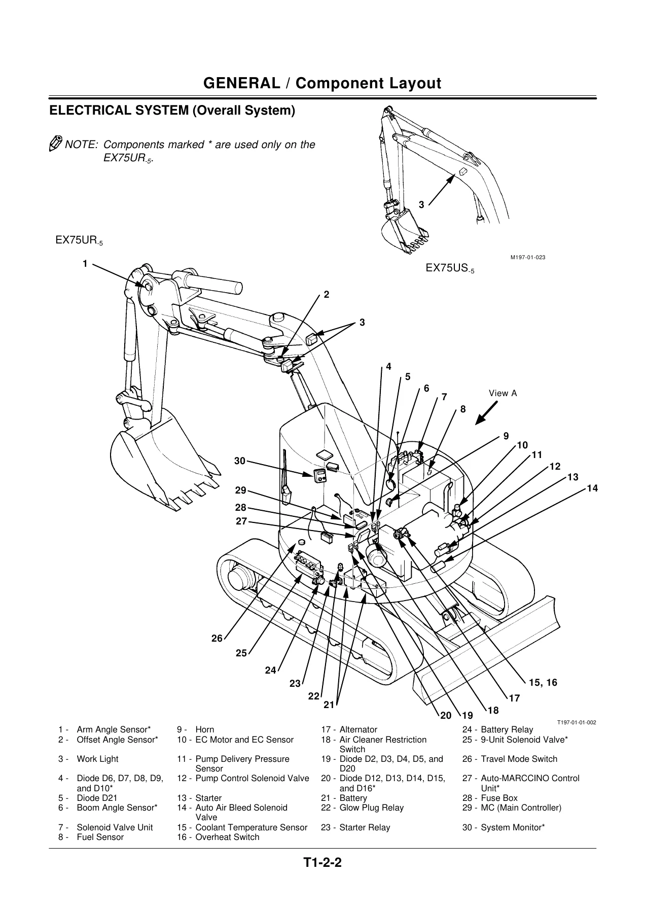
- Section 1 General – Group 1 Specifications (specification tables, working ranges and machine transportation dimensions, component specification); Group 2 Component Layout (main components, electrical system overall, monitor and switches)
- Section 2 System – Group 1 Control System (outline, engine control, pump control, other controls); Group 2 Front Control System (outline, front function control); Group 3 Hydraulic System (outline, main circuit, pilot circuit); Group 4 Electrical System (outline, power source circuit, bulb check, preheat, engine start, charging, surge voltage prevention, accessory, engine stop)
- Section 3 Component Operation – Group 1 Pump Device; Group 2 Swing Device; Group 3 Control Valve; Group 4 Pilot Valve; Group 5 Travel Device; Group 6 Others (Uppertructure); Group 7 Others (Undercarriage)
- Section 4 Operational Performance Test – Group 1 Introduction; Group 2 Standard; Group 3 Engine Test; Group 4 Excavator Test; Group 5 Component Test; Group 6 Adjustment
- Section 5 Troubleshooting – Group 1 General; Group 2 Component Layout; Group 3 Troubleshooting A; Group 4 Troubleshooting B; Group 5 Troubleshooting C; Group 6 Troubleshooting D; Group 7 Electrical System Inspection
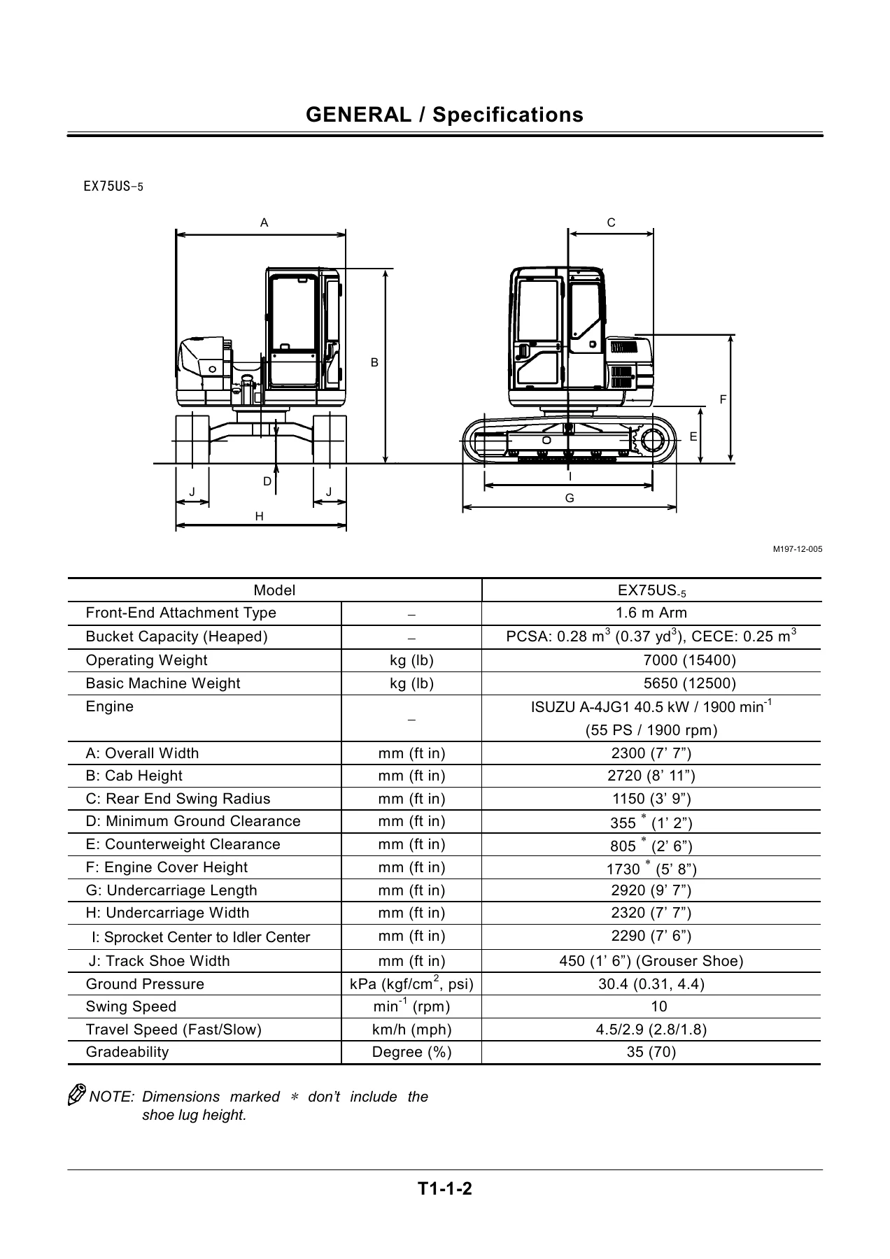
The opening groups of the manual establish the machine itself: the specification tables set out operating weight, bucket capacity, engine rating, overall width, cab height, rear end swing radius, ground clearance, counterweight clearance, undercarriage length and width, track shoe width, ground pressure, swing speed, travel speed and gradeability for both the EX75UR-5 and the EX75US-5. Working ranges follow with maximum digging reach, digging depth, cutting height, dumping height, transport height, transport length, minimum swing radius and, for the offset model, the maximum offset to either side. The component specification section then walks the engine, cooling system, lubrication system, starting system, preheat system, engine stop system, alternator, fuel system, engine performance figures, radiator and oil cooler assembly and battery.
Hydraulic and Electrical Coverage in This EX75UR-5 / EX75US-5 Manual
The hydraulic side of the manual is unusually complete. The main pump is documented as the AP2D36LV1RS6 variable displacement swash plate axial plunger unit with a theoretical maximum flow rate of 68.4 L/min, alongside main pump 3 and the pilot pump as fixed displacement gear pumps, and the two control valve blocks – the KVMM-80-HD with its 5-spool and 4-spool sections and the MVX 14 with a three-spool section on the EX75UR-5 and a two-spool section on the EX75US-5. The text explains how pump swash angle regulation, travel mode control, flow combining, boom anti-drift, main relief, overload relief and make-up functions actually work, with cross sections of the pump regulator, the boom anti-drift valve, the main relief valve, the overload relief valve and the control valve spools.
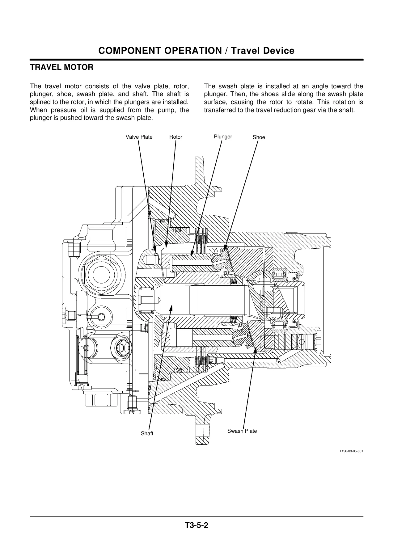
Swing and travel receive the same treatment. The swing motor is documented as the MFB-50-007 fixed displacement swash plate axial plunger motor with a two-stage reduction planetary gear, a wet multi-disc negative parking brake and a valve unit containing make-up and relief valves. The travel device is presented with the brake valve, travel motor and two-stage travel reduction gear, including the slow/fast swash plate change, the negative-type parking brake and the counterbalance brake valve that governs downhill travel. Pilot valves, the pilot shut-off valve, the shockless valve, the 9-unit solenoid valve, the solenoid valve unit with travel mode, arm oil flow combining and emergency stop valves, the EC motor, the swing bearing, the centre joint and the track adjuster each have their own component operation pages.
Operational Performance Test and Troubleshooting
Section 4 is where this EX75UR-5 EX75US-5 technical manual becomes a working tool rather than a reference. It lays out the standard performance table with target engine speeds for fast idle, fast idle when relieving, E-mode fast idle, slow idle and auto-idle, engine compression pressure, valve clearance, nozzle injection pressure, injection timing, travel speed, track revolution speed, mistrack allowance, swing speed, swing function drift, maximum swingable slant angle, swing bearing play, hydraulic cylinder cycle times, dig function drift limits, control lever operating force and control lever stroke. Component test procedures follow for primary and secondary pilot pressure, main relief valve set pressure on both control valves, swing relief, travel relief, overload relief, main pump flow rate, swing motor drainage and travel motor drainage, each with the adapter and gauge setup described and the adjustment method spelled out.
Troubleshooting is split into four tracks. Troubleshooting A handles the main controller fault codes, including code 01 for an abnormal EC angle sensor and code 07 for an abnormal engine control dial angle. Troubleshooting B starts from symptoms – slow engine, engine that will not stop, auto-idle that will not engage, slow actuator, drifting cylinders, slow swing, one track that will not rotate, mistracking during combined travel and front attachment operation, blade drift and engine stall when blade or swing is used. Troubleshooting C covers the monitor panel: coolant temperature gauge, fuel gauge, indicator light check, alternator indicator, engine oil pressure indicator, overheat indicator, fuel level indicator, air filter restriction indicator, buzzer and hour meter. Troubleshooting D is dedicated to the EX75UR-5 front control system, with the Auto-MARCCINO control unit fault code list and procedures for the angle sensors, pilot pressure sensors, pump delivery pressure sensor, oil temperature sensor, sensor power source and the 9-spool solenoid valve unit. The final group covers electrical system inspection, connector handling, fuse continuity, fusible link inspection, battery voltage, alternator checks, continuity checks, voltage and current checks, false-signal checking and the test harnesses.
Attached Diagrams and Harness Sheets
The document lists the sheets attached to the volume: the EX75UR-5 hydraulic circuit diagram, the EX75US-5 hydraulic circuit diagram, the EX75UR-5 electrical circuit diagram, the EX75US-5 electrical circuit diagram, the connector sheets for both models, the engine harness sheets for both models, and the cab harness sheets for both models. The electrical circuit diagrams carry the monitor control logic, switch control logic, lamp unit, regulator, engine control dial, EC motor, pump displacement solenoid, travel mode solenoid, glow relay, battery relay, starter relay, load damp relay and the Auto-MARCCINO wiring for the offset machine, while the harness sheets show connector part numbers, terminal counts and the routing through the engine bay, cab floor and cab wall.
Repairs and Diagnostics This Hitachi Excavator Manual Supports
The Hitachi EX75UR-5 EX75US-5 technical manual and wiring diagrams support the full range of service work on these compact excavators. Engine speed adjustment and engine learning are covered step by step, including the warning that engine learning must be repeated after the engine, engine control cable, EC motor or main controller has been removed or replaced. The boom lowering method when the engine has stalled is described with the overload relief valve loosening limits and the caution about not exceeding three-quarters of a turn. Initial setting of the angle sensors, assembly and adjustment of the arm angle sensor link with the 330 mm end rod dimension, and initialisation of the depth limit control system are all set out with the exact switch positions and expected results. Front acceleration and deceleration speed adjustment through the 9-spool solenoid valve is documented, and the arm oil flow combining checks explain how to confirm whether the delivery pressure at the SB port is above or below 3.33 MPa.
For a shop running an EX75UR-5 or EX75US-5, that combination matters. Fault codes point at a circuit, the operational performance tests confirm whether that circuit is actually out of specification, the component operation pages explain the mechanism behind the number, and the adjustment procedures put it back. Torque values, relief set pressures with their shim and screw-turn conversion references, cycle time targets, drift limits and lever stroke figures are all given in SI units with MKS and English equivalents in parentheses.
Why This Manual Is Worth Having
Compact excavators in this class hide their problems well – a worn swash plate, a bound spool, a drifting counterbalance valve or a failing angle sensor all show up first as a vague complaint about speed or power. The measurement thresholds, fault-code definitions and step-by-step flow charts in this manual replace guesswork with a defined test sequence, and the hydraulic and electrical circuit diagrams let a technician trace a circuit end to end instead of replacing parts until something changes. The Auto-MARCCINO pages in particular are difficult to find anywhere else, covering depth limit control, cab collision prevention, front motion restriction, arm oil flow combining and system malfunction display for the offset EX75UR-5.
IMAGES PREVIEW
Delivery is instant. The PDF is sent as a download link immediately after payment clears – no shipping, no waiting, no physical binder to lose. Open it on a laptop in the workshop, a tablet on the machine or a phone at the bench, zoom into the cross sections and circuit diagrams, and print whichever page you want to take under the machine. Keep it on file and the same copy is still there for the next service interval.
Reviews
There are no reviews yet.