
Hitachi ZAXIS 200-3 to 270-3 Hydraulic Excavator Technical Manual (Operational Principle) TO1V1-E
Original price was: $34.95.$21.95Current price is: $21.95.
Factory Technical Manual (Operational Principle) TO1V1-E covering Hitachi ZAXIS 200-3, 225US-3, 225USR-3, 240-3, 250-3 and 270-3 class hydraulic excavators. Full system operating principles, hydraulic and electrical circuits, pump/valve control theory, and component operation diagrams.
Description
Hitachi ZAXIS 200-3 to 270-3 Series Technical Manual (Operational Principle) — TO1V1-E
This Hitachi ZAXIS 200-3 to 270-3 Series Technical Manual (Operational Principle) — published under Hitachi volume number TO1V1-E — is the factory-issued service engineering reference for the 200-3, 225US-3, 225USR-3, 240-3, 250-3 and 270-3 class hydraulic excavators. It explains how each machine system actually works: how the main pumps are regulated, how the MC and ECM controllers cooperate over the CAN bus, how the control valve proportions flow, how the swing and travel devices respond to pilot pressure, and how the electrical circuits sequence every major operation. It is the volume a technician reads before opening the Workshop Manual, because it establishes the operating logic behind every diagnostic step and repair procedure covered in the Troubleshooting and Workshop volumes.
File Details
- Manual type: Technical Manual (Operational Principle)
- Volume / publication no.: TO1V1-E
- Brand: Hitachi Construction Machinery
- Machine type: Hydraulic Excavator
- Series: ZAXIS 200-3 to 270-3 class
- Language: English
- File format: PDF
- Page count: 424 pages
- Revision data current to: 9 December 2008
Companion Volumes in the Same Service Manual Set
Hitachi splits the ZAXIS 200-3 to 270-3 Service Manual into three separate books. This listing is for the Operational Principle volume only:
- Technical Manual (Operational Principle): Vol. No. TO1V1-E — this document
- Technical Manual (Troubleshooting): Vol. No. TT1V1-E
- Workshop Manual: Vol. No. W1V1-E
If you are diagnosing a fault or rebuilding a component, you will want all three. This volume gives you the theory; the Troubleshooting volume gives you the diagnostic decision trees and the Workshop volume gives you the disassembly, inspection and reassembly procedures.
Chapters Covered
The manual is organised into three main sections, each subdivided into numbered groups:
- Section 1 — General
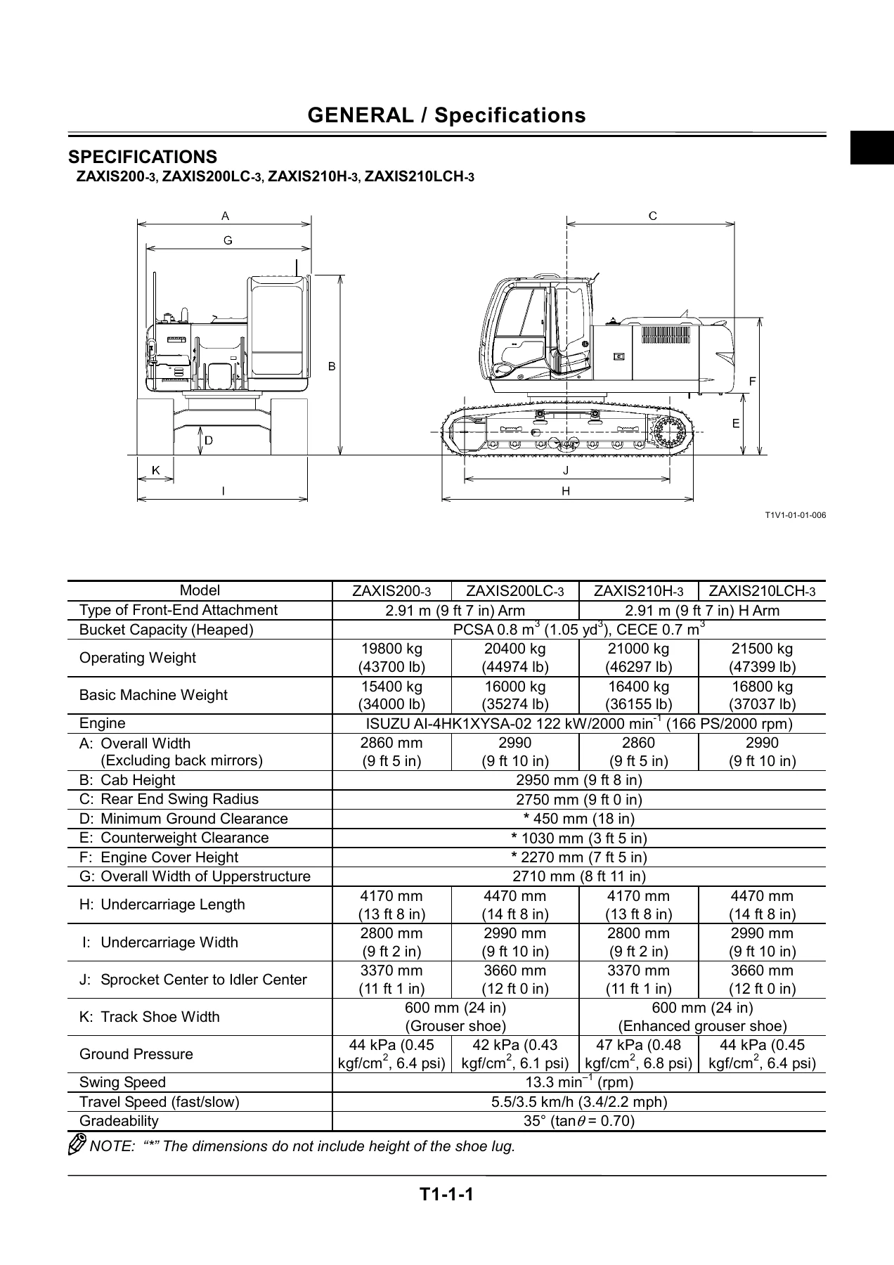
- Group 1: Specifications
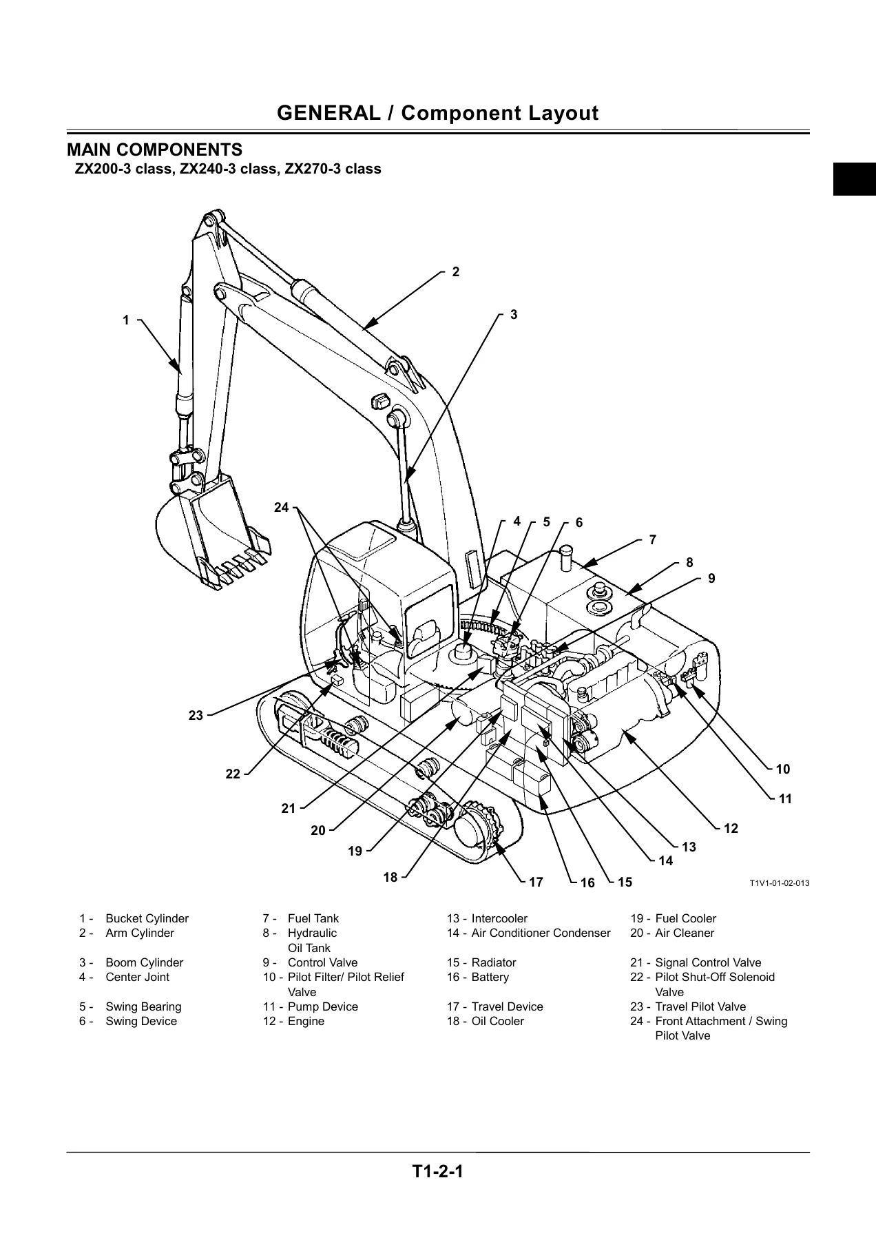
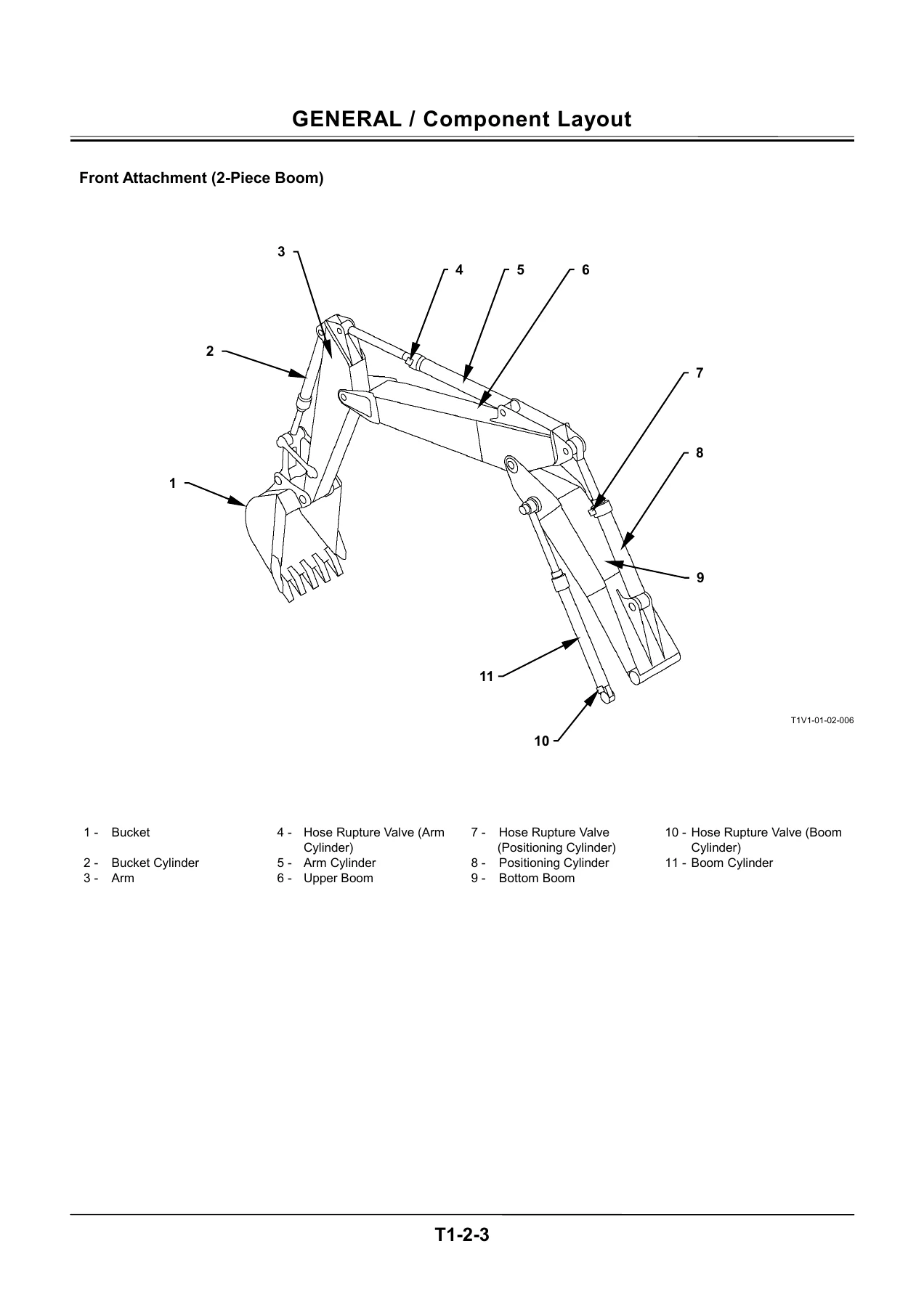
- Group 2: Component Layout
- Group 3: Component Specifications
- Section 2 — System
- Group 1: Controller (MC, ECM, ICF and CAN bus topology)
- Group 2: Control System (engine, pump and valve control)
- Group 3: ECM System (fuel injection, engine start, EGR, fuel correction, engine stop)
- Group 4: Hydraulic System (pilot circuit, main circuit, boom lower meter-in cut)
- Group 5: Electrical System (main, accessory, starting, charging, surge prevention, pilot shut-off, security lock, engine stop, security horn, working light, wiper)
- Section 3 — Component Operation
- Group 1: Pump Device (main pump, regulator, solenoid valves, pilot pump, delivery and control pressure sensors)
- Group 2: Swing Device (reduction gear, swing motor, parking brake, valve unit, swing dampener valve)
- Group 3: Control Valve (main relief, overload relief, flow combiner, anti-drift, flow rate control, regenerative, digging regenerative, boom lower meter-in cut, auxiliary flow combiner and bypass shut-out)
- Group 4: Pilot Valve (front attachment/swing, travel, auxiliary and positioning)
- Group 5: Travel Device (reduction gear, travel motor, parking brake, travel mode change, travel brake valve)
- Group 6: Signal Control Valve (shuttle valve, shockless valve, pump 1 and 2 flow rate control valves, flow combiner valve spool, bucket flow rate control spool, swing parking brake release spool, arm 1 flow rate control spool)
- Group 7: Others — Upperstructure (pilot shut-off valve, solenoid valve units, hose rupture valve, pilot relief valve)
- Group 8: Others — Undercarriage (swing bearing, center joint, track adjuster)
What This Operational Principle Manual Actually Gives You
Rather than a parts or repair procedure book, this is the systems-theory reference. Every major subsystem is broken open — not into components on a bench, but into function. For the pump device, for example, the manual walks through the servo piston, sleeve A and B, spool A and B, load pistons and inner/outer springs, then explains each of the four regulator control functions in turn: control by pump control pressure Pi, control by own or opponent pump delivery pressure, control by pilot pressure from the torque control solenoid valve, and control by pilot pressure from the maximum pump flow rate limit control solenoid valve. The up-stroke and down-stroke of the regulator are diagrammed step by step so you can see exactly which spring and which land is doing the work at any given moment.
The same depth is applied across the swing device — including the counterintuitive behaviour of the swing dampener valve, whose two combination valves (A and B) alternate between relieving pressure at port BM and relieving aftershock pressure at port AM. That’s the reason a ZAXIS 200-3 class machine does not rock to a stop like a machine with a plain relief valve.
The Control Valve section (Section 3, Group 3) is particularly extensive: it covers the flow combiner valve, main relief valve with its set-pressure-increasing operation via solenoid valve unit (SG), overload relief valve with make-up function, boom/arm/bucket regenerative valves, anti-drift valves for both boom and arm, all four flow rate control valves (boom, arm 1, arm 2, bucket and auxiliary), the digging regenerative valve, the boom lower meter-in cut valve — including the difference between boom-lowering with the front attachment above ground and the jack-up condition — and the auxiliary flow combiner plus bypass shut-out valve logic for both single and combined operations.
On the electrical side, the manual traces every circuit from the battery terminal through the fuse box, relays and switches to the load. Starting circuit, charging circuit (with alternator regulator theory), surge voltage prevention via the load damp relay, pilot shut-off circuit, security lock circuit, engine stop circuit, security horn circuit, working light circuit and wiper circuit are all drawn and described. The CAN bus topology linking MC, ECM, ICF and the monitor unit is fully explained, including how each controller uses the CAN High / CAN Low potential difference to arbitrate bus levels.
Model Coverage by Series Group
- 200-3 class: ZAXIS200-3, 200LC-3, 210H-3, 210LCH-3, 210K-3, 210LCK-3, 210-3, 210LC-3, 210LCN-3
- 225US-3 class: ZAXIS225US-3, 225USLC-3
- 225USR-3 class: ZAXIS225USR-3, 225USRLC-3, 225USRLCK-3
- 240-3 class: ZAXIS240-3, 240LC-3, 240N-3, 250H-3, 250LC-3, 250LCN-3, 250LCH-3, 250K-3, 250LCK-3
- 270-3 class: ZAXIS270-3, 270LC-3, 280LC-3, 280LCN-3
Engine Coverage
- ZX200-3 class, ZX225US-3 class, ZX225USR-3 class: ISUZU 4HK1XYSA-02, 114 kW/1800 min-1 (HP Mode: 122 kW/2000 min-1)
- ZX240-3 class: ISUZU 4HK1XYSA-01, 127 kW/1900 min-1 (HP Mode: 132 kW/2000 min-1)
- ZX270-3 class: ISUZU 4HK1XYSA-03, 136 kW/2000 min-1 (HP Mode: 140 kW/2100 min-1)
All three engines share the same 4-cylinder, 115 mm x 125 mm bore and stroke, 5193 cm³ displacement, 17.5 compression ratio, common rail HP3 fuel system, RHF55 turbocharger and 24 V glow plug preheat system.
Systems Broken Open Step by Step
- Engine control: engine control dial control, HP mode, travel HP mode, E mode, auto-idle, auto-warming up, idle speed-up, heater control, attachment operation speed increase and limit control
- Pump control: speed sensing control, travel torque-up, attachment pump torque decrease, pump 1/2/3 flow rate limit control
- Valve control: power digging, auto-power lift, arm regenerative, digging regenerative, travel motor swash angle control, HSB and NPK breaker control, secondary and primary crusher control
- Hydraulics: pilot circuit, main circuit, neutral and single-operation circuits, swing + boom raise combined circuit, travel + arm roll-in combined circuit, positioning circuit and auxiliary circuit
Why This Volume Matters
A common mistake on ZAXIS 200-3 series machines is to chase a symptom through the Troubleshooting volume without first understanding what the system is supposed to do. This Operational Principle manual removes that guesswork. When you know that the boom lower meter-in cut valve closes the boom flow control valve only when boom cylinder bottom pressure is high — and stays open during jack-up — you stop misreading a machine that behaves differently at different boom angles. When you understand that the travel torque-up control raises the P-Q curve to balance pump 1 and pump 2 during single travel operation, a mistracking complaint becomes a pressure sensor check rather than a pump replacement.
The manual also gives you the exact reference pressures you will be comparing against: main relief at 34.3 MPa (350 kgf/cm², 4980 psi) normal and 36.3 MPa (370 kgf/cm²) in power digging; overload relief at 37.2 MPa (380 kgf/cm²) on boom lower, arm roll-in and bucket roll-in; 39.2 MPa (400 kgf/cm²) on boom raise, arm roll-out and bucket roll-out. Control valve, swing relief and travel relief set pressures are all here, alongside the pump displacements, travel reduction gear ratios and swing reduction ratios for each class.
Who This Manual Suits
- Field service technicians diagnosing hydraulic or electrical faults on any ZAXIS 200-3 through 270-3 class machine
- Workshop engineers rebuilding pumps, swing devices, travel motors or control valves
- Fleet maintenance planners building accurate scheduled-service and inspection routines
- Technical trainers and apprentices studying the operating logic of modern hydraulic excavators
- Owners of a ZAXIS200-3, 225US-3, 240-3 or 270-3 wanting the factory documentation on hand for their own machine
IMAGES PREVIEW
Instant PDF Delivery
The manual is delivered as an instant-download PDF. There is no shipping, no waiting for a physical book, and no region restrictions. Open it on a laptop in the cab, on a tablet at the bench, or print the sections you need for a specific job — the pump regulator walk-through, the pilot valve output curve, the CAN bus topology, the starting circuit. Every diagram, output curve and cross-section is included at full resolution so the numbered components stay readable at the size you need to work at.
Whether you are troubleshooting a single fault or preparing a full system-level diagnostic, having the correct Operational Principle reference for your ZAXIS 200-3 to 270-3 class excavator on the same bench as the machine is the difference between swapping parts and repairing them.
Reviews
There are no reviews yet.