
Hitachi Zaxis 200-3 230-3 270-3 Excavator Technical Manual Operational Principle
Original price was: $34.95.$19.95Current price is: $19.95.
Factory Technical Manual (Operational Principle) for Hitachi Zaxis 200-3, 230-3 and 270-3 excavators. Part No. TO1V1-E-00. Explains how every major hydraulic, electrical, engine and control system is designed to operate. 383-page PDF.
Description
Hitachi Zaxis 200-3 230-3 270-3 Excavator Technical Manual Operational Principle
The Hitachi Zaxis 200-3 230-3 270-3 Excavator Technical Manual Operational Principle is the document that explains how these machines are designed to work. Published by Hitachi Construction Machinery under Part No. TO1V1-E-00, it is the operational-principle volume of the three-part service documentation set, sitting alongside the Troubleshooting manual (TT1V1-E-00) and the Workshop Manual (W1V1-E-00). Where the troubleshooting volume tells you what to test, this one tells you why the system behaves the way it does.
This is not a repair guide and it is not a workshop manual. It is the theoretical and functional reference for the Zaxis 200-3, 230-3 and 270-3 class excavators. Every major system — the main pumps, the control valve, the swing and travel devices, the pilot circuit, the signal control valve, the engine control module, the main controller, the information controller and the entire electrical architecture — is opened up and explained in working-principle terms. If you need to understand the machine before you diagnose it, this is the document that gives you that foundation.
File Details
- Manual Type: Technical Manual (Operational Principle)
- Brand: Hitachi Construction Machinery
- Models Covered: ZAXIS 200-3, 230-3, 270-3 Excavator
- Document Number: TO1V1-E-00
- Language: English
- Page Count: 383
- File Format: PDF
- Engine Coverage: Isuzu 4HK1XYSA-02, 4HK1XYSA-01, 4HK1XYSA-03
- Publication: Hitachi Construction Machinery Co. Ltd.
Chapters Covered
The manual is organised into three sections, each divided into numbered groups. The contents below reflect the actual structure of the document.
- Section 1 — General
- Group 1: Specifications
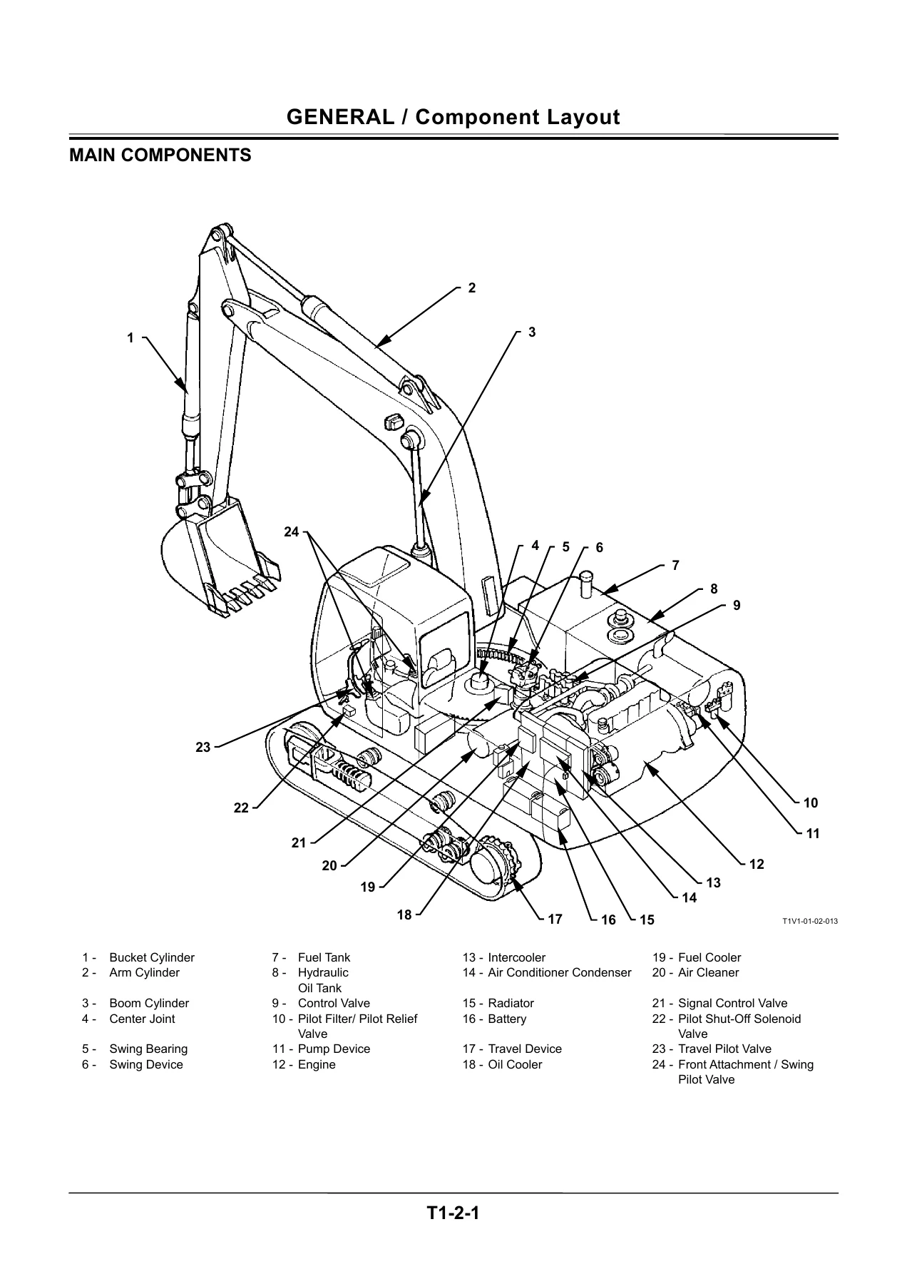
- Group 2: Component Layout
- Group 3: Component Specifications
- Section 2 — System
- Group 1: Controller (MC Main Controller, ECM Engine Control Module, ICF Information Controller, CAN network)
- Group 2: Control System (Engine Control, Pump Control, Valve Control, Other Controls)
- Group 3: ECM System (Fuel Injection Control, Engine Start Control, EGR Control, Fuel Injection Amount Correction, Engine Stop Control)
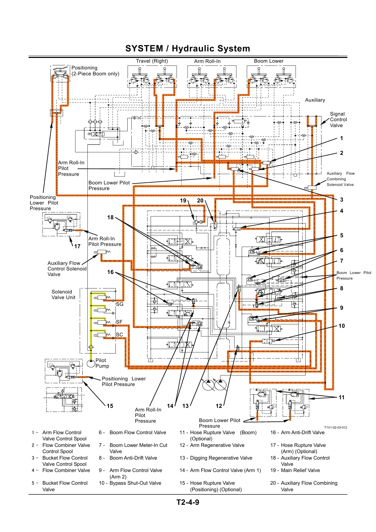
- Group 4: Hydraulic System (Pilot Circuit, Main Circuit, Boom Lower Meter-In Cut Control)
- Group 5: Electrical System (Main Circuit, Electric Power Circuit, Accessory Circuit, Starting Circuit, Charging Circuit, Surge Voltage Prevention Circuit, Pilot Shut-Off Circuit, Security Lock Circuit, Engine Stop Circuit, Security Horn Circuit, Working Light Circuit, Wiper Circuit)
- Section 3 — Component Operation
- Group 1: Pump Device (Main Pump, Regulator, Solenoid Valve, Pilot Pump, Delivery Pressure Sensor, Control Pressure Sensor)
- Group 2: Swing Device (Swing Reduction Gear, Swing Motor, Swing Parking Brake, Valve Unit, Swing Dampener Valve)
- Group 3: Control Valve (Flow Combiner Valve, Main Relief Valve, Overload Relief Valve, Regenerative Valve, Anti-Drift Valve, Flow Rate Control Valve, Digging Regenerative Valve, Boom Lower Meter-In Cut Valve, Auxiliary Flow Combiner Valve and Bypass Shut-Out Valve)
- Group 4: Pilot Valve (Front Attachment/Swing Pilot Valve, Travel Pilot Valve, Auxiliary/Positioning Pilot Valve, Shockless Function)
- Group 5: Travel Device (Travel Reduction Gear, Travel Motor, Parking Brake, Travel Mode Change, Travel Brake Valve)
- Group 6: Signal Control Valve (Pilot Port, Shuttle Valve, Shockless Valve, Pump 1 and Pump 2 Flow Rate Control Valves, Bucket Flow Rate Control Valve Control Spool, Flow Combiner Valve Control Spool, Swing Parking Brake Release Spool, Arm 1 Flow Rate Control Valve Control Spool)
- Group 7: Others — Upperstructure (Pilot Shut-Off Valve, Solenoid Valve, Hose Rupture Valve, Pilot Relief Valve)
- Group 8: Others — Undercarriage (Swing Bearing, Center Joint, Track Adjuster)
Taken as a whole, the Hitachi Zaxis 200-3 230-3 270-3 Technical Manual Operational Principle gives a technician a complete functional picture of the machine. You get the specification data for all three classes, the component layout drawings, and then a system-by-system explanation of how the engine, pumps, valves, motors, cylinders and electronic controllers interact. The ECM section alone covers fuel injection control, injection rate control, injection timing, EGR control, engine start control and engine stop control. The hydraulic section covers the pilot circuit, the main circuit and the boom lower meter-in cut control. The electrical section walks through every major circuit from the electric power circuit through to the wiper circuit.
What Makes This Manual Useful
Operational principle manuals are the least understood and most underrated part of a service documentation set. Most people reach for the workshop manual when something breaks, but the workshop manual assumes you already understand how the system works. This manual is where that understanding comes from. It explains the reasoning behind the design — why the pump regulator behaves the way it does under load, how the arm regenerative control decides when to open, what the main controller is actually calculating when it sends a signal to the torque control solenoid valve, and how the engine control module decides fuel injection amount and timing.
For the Zaxis 200-3, 230-3 and 270-3 class machines, that level of understanding matters. These excavators use a sophisticated hydraulic and electronic control architecture — speed sensing control, travel torque-up control, arm regenerative control, digging regenerative control, auto-power lift control, power digging control, travel motor swash angle control, and a full CAN bus network linking the main controller, engine control module, information controller and monitor unit. Without the operational principle behind each of these functions, diagnosis becomes guesswork. With it, you can follow the logic from input signal to output action and identify where the chain breaks.
The manual also includes the specification data for each machine class. The ZX200-3 class uses the Isuzu 4HK1XYSA-02 engine rated at 122 kW / 2000 min-1 in HP mode. The ZX240-3 class uses the 4HK1XYSA-01 at 132 kW / 2000 min-1. The ZX270-3 class uses the 4HK1XYSA-03 at 140 kW / 2150 min-1. Working ranges, dimensions, operating weights, ground pressure, swing speed, travel speed and gradeability are all listed. The hydraulic component specifications cover the main pump, regulator, pilot pump, control valve, swing parking brake, travel device, travel motor and travel brake valve.
Who This Manual Is For
This Hitachi Zaxis 200-3 230-3 270-3 Excavator Technical Manual Operational Principle is written for the experienced technician. It assumes you are comfortable reading hydraulic circuit diagrams, electrical schematics and control system flow charts. It is not a step-by-step repair guide and it does not replace the Workshop Manual. What it does is give you the theoretical grounding that makes the workshop and troubleshooting volumes usable.
It is equally useful for equipment owners who want to understand their machine at a deeper level, for technical trainers preparing instructional material, and for anyone involved in diagnosing performance complaints, hydraulic faults, electrical faults or control system issues on these excavators. The component operation section, in particular, is valuable because it explains the internal working of each major component — the pump regulator, the control valve spools, the swing motor, the travel motor, the pilot valve, the signal control valve and the hose rupture valve.
Systems and Functions Covered in Detail
The system section of the manual is where the operational principle is laid out in full. Under engine control, the manual explains the engine control dial, HP mode control, travel HP mode control, E mode control, auto-idle control, auto-warming up control, idle speed-up control, heater control, and the optional attachment operation speed increase and limit controls. Under pump control, it covers speed sensing control, travel torque-up control, attachment pump torque decrease control, and pump flow rate limit controls. Under valve control, it covers power digging control, auto-power lift control, arm regenerative control, digging regenerative control, travel motor swash angle control, and the optional breaker, crusher and auxiliary attachment controls.
Under the ECM system, the manual explains fuel injection control, engine start control, EGR control, fuel injection amount correction and engine stop control. Under the hydraulic system, it covers the pilot circuit and the main circuit. Under the electrical system, it walks through the electric power circuit, accessory circuit, starting circuit, charging circuit, surge voltage prevention circuit, pilot shut-off circuit, security lock circuit, engine stop circuit, security horn circuit, working light circuit and wiper circuit.
Why This Manual Matters
When you are working on a Zaxis 200-3, 230-3 or 270-3 excavator, the difference between a correct repair and a repeat failure often comes down to understanding how the system was designed to behave. The Hitachi Zaxis 200-3 230-3 270-3 Technical Manual Operational Principle gives you that understanding. It is the document that explains the machine’s logic — the relationship between the main controller, the engine control module, the pump regulators, the control valve and the various sensors and solenoid valves.
Whether you are diagnosing a hydraulic drift issue, a control valve malfunction, a pump flow problem, a travel speed complaint, an engine control fault or an electrical circuit failure, the operational principle behind the system is the starting point. Without it, you are working blind. With it, you can reason through the system, isolate the faulty stage and make a confident repair.
IMAGES PREVIEW
This manual is delivered as an instant PDF download. There is no shipping, no waiting and no physical media to lose. You can open it on any device — laptop, tablet or phone — and print the pages you need for the workshop. The 383-page document is fully navigable and gives you the complete operational principle coverage for the Zaxis 200-3, 230-3 and 270-3 class excavators in one file.
Reviews
There are no reviews yet.