
Hitachi Zaxis 40U 50U Excavator Technical & Workshop Manual T1LDE-00 PDF
Original price was: $39.95.$24.95Current price is: $24.95.
Complete Hitachi Zaxis 40U and 50U excavator Technical and Workshop Manual (Vol. T1LDE-00 / W1LDE-00). Covers hydraulic and electrical systems, component operation, performance testing, troubleshooting, and full disassembly/assembly procedures for engine, upperstructure, undercarriage, and front attachment.
Description
Hitachi Zaxis 40U 50U Technical & Workshop Manual — T1LDE-00
This is the complete Hitachi Zaxis 40U and Zaxis 50U excavator Technical and Workshop Manual, published under document number T1LDE-00 (Technical Manual) and W1LDE-00 (Workshop Manual). It is the two-portion service documentation set that Hitachi produced for these compact excavators, covering both the systems theory a technician needs to understand how the machine works and the hands-on procedures required to maintain, diagnose, and repair it.
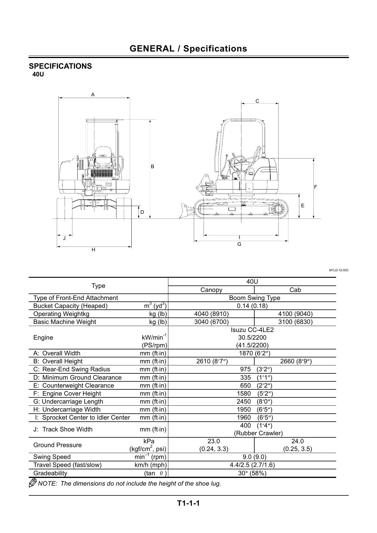
The manual applies to the Zaxis 40U and Zaxis 50U canopy and cab variants, powered by the Isuzu 4LE2 diesel engine rated at 30.5 kW / 2200 min-1 (41.5 PS / 2200 rpm). Whether you are servicing the hydraulic system, tracing an electrical fault, performing a performance test, or pulling a travel device for rebuild, this Hitachi Zaxis 40U 50U manual provides the procedures, specifications, and component-level detail to do the job correctly.
File Details
- Manual Type: Technical Manual and Workshop Manual (two-portion service set)
- Brand / Manufacturer: Hitachi
- Models Covered: Zaxis 40U, Zaxis 50U
- Engine: Isuzu 4LE2 (CC-4LE2), 4-cylinder, water-cooled, direct injection diesel
- Document Numbers: T1LDE-00 (Technical Manual), W1LDE-00 (Workshop Manual)
- Language: English
- File Format: PDF
- Page Count: 657 pages (including electrical and hydraulic circuit diagrams)
Chapters Covered
The Hitachi Zaxis 40U 50U Technical and Workshop Manual is organised into the following sections, each addressing a major area of the machine:
Technical Manual
- Hydraulic System
- Outline
- Pilot Circuit — machine operation control, pump control (flow rate control), travel mode control, swing parking brake release
- Main Circuit — combined operation circuits, pump operation, pressure compensator operation
- Electrical System
- Outline — main circuit and monitor circuit
- Power Circuit (key switch OFF)
- Indicator Light Check Circuit / Accessory Circuit (key switch ON)
- Preheat Circuit (key switch ON)
- Starting Circuit (key switch START)
- Charging Circuit (key switch ON)
- Engine Stop Circuit (key switch OFF)
Component Operation
- Pump Device — outline, main pump P1, power control, flow rate control, PS valve
- Revolution Sensing Valve — outline, operation (variable metering valve and differential reducing valve)
- Swing Device — outline, swing motor, parking brake, valve unit (make-up valve and relief valve), swing reduction gear
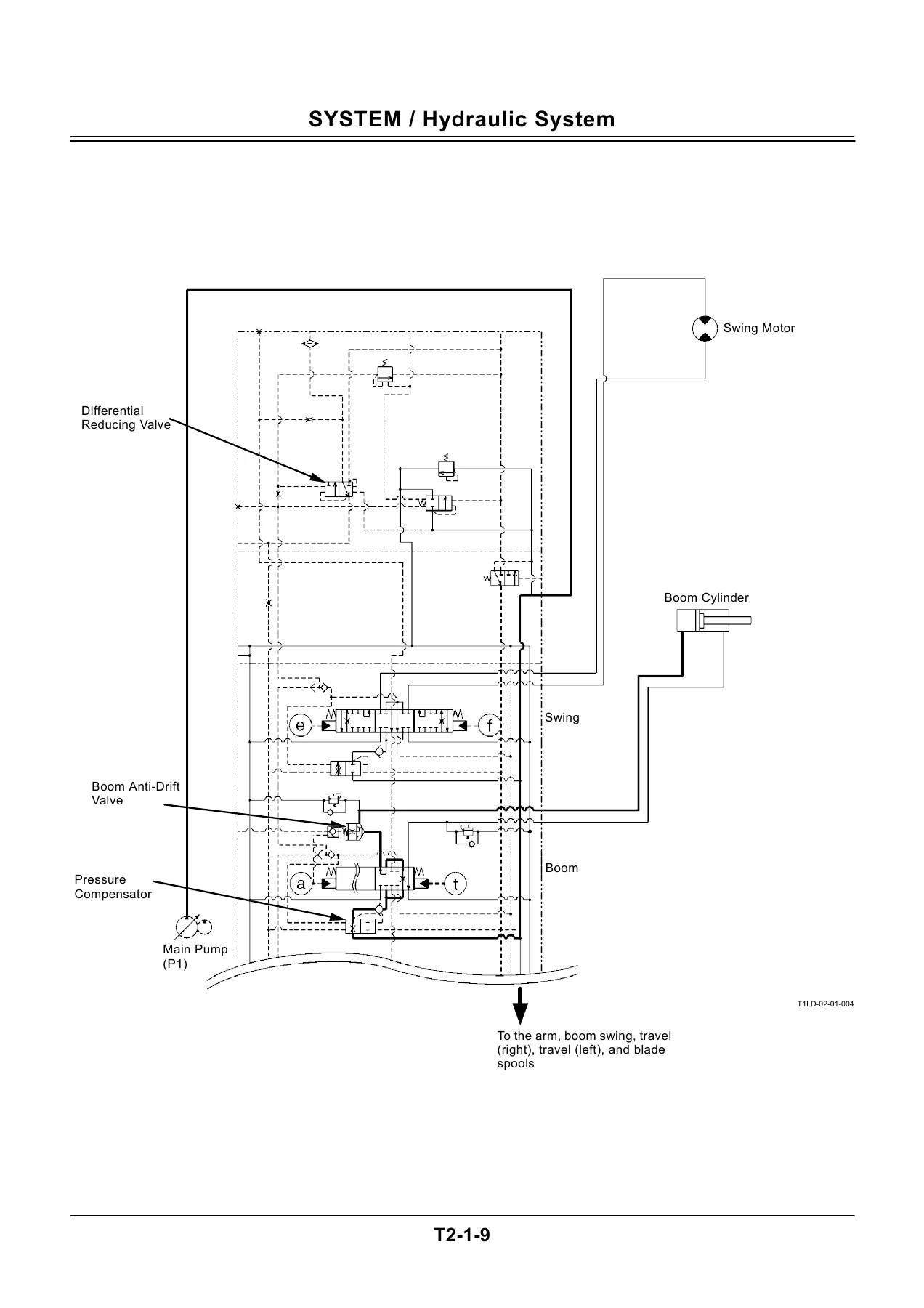
- Control Valve — outline, hydraulic circuit, main relief valve, overload relief valve, make-up valve, main shut-off valve, boom anti-drift valve, unload valve, differential reducing valve, pressure compensator, variable relief valve
- Pilot Valve — outline, operation (front attachment, swing, travel, blade, boom swing pilot valves)
- Travel Device — outline, travel motor, travel brake valve (counterbalance valve, relief valve, travel speed changeover valve), travel reduction gear
- Others (Upperstructure) — solenoid valve unit, pilot relief valve
- Others (Undercarriage) — swing bearing, center joint, track adjuster
Operational Performance Test
- Introduction — operational performance test, preparation for performance tests
- Standard — operational performance standard
- Engine Test — engine speed, engine compression pressure, valve clearance, nozzle check, injection timing
- Excavator Test — travel speed, track revolution speed, mistrack check, travel motor leakage, swing speed, swing function drift check, swing motor leakage, maximum swingable slant angle, swing bearing play, hydraulic cylinder cycle time, dig function drift, control lever operating force, control lever stroke
- Component Test — primary pilot pressure, secondary pilot pressure, main relief valve set pressure, overload relief valve set pressure, swing motor drainage, travel motor drainage, revolution sensing valve output pressure, pump delivery pressure, pump driving torque
Troubleshooting
- Diagnosing Procedure — introduction, diagnosing procedure (five basic steps)
- Troubleshooting A — troubleshooting A procedure, engine system, actuator operating system, front attachment system, swing system, travel system, blade system, boom swing system
- Troubleshooting B — malfunction of coolant temperature gauge, fuel gauge, alternator indicator, engine oil pressure indicator, overheat indicator, fuel level indicator, buzzer, hour meter
- Electrical System Inspection — precautions for inspection and maintenance, fuse continuity test, battery voltage check, voltage check, continuity check
Workshop Manual
- Section 1 — General Information
- Precautions for Disassembling and Assembling
- Tightening — tightening torque specification, torque chart, piping joint, periodic replacement of parts
- Bleeding Air — bleed air from hydraulic oil tank
- Painting
- Section 2 — Upperstructure
- Canopy — remove and install
- Counterweight — remove and install
- Pump Device — remove and install, disassemble, assemble, maintenance standard
- Control Valve — remove and install, disassemble and assemble, relief valve and make-up valve removal/installation, body disassembly/assembly, unload section, spool, boom section, shuttle valve and pressure compensation valve
- Swing Device — remove and install, disassemble/assemble swing reduction gear, disassemble/assemble swing motor, maintenance standards
- Pilot Valve — remove and install front pilot valve, travel pilot valve, blade pilot valve, boom swing pilot valve; disassemble/assemble front pilot valve, travel pilot valve, blade and boom swing pilot valve
- Solenoid Valve — disassemble and assemble
- Revolution Sensing Valve — remove and install, disassemble, assemble
- Section 3 — Undercarriage
- Swing Bearing — remove and install
- Travel Device — remove and install, disassemble, assemble, maintenance standards
- Center Joint — remove and install, disassemble, assemble
- Track Adjuster — remove and install, disassemble, assemble
- Front Idler — remove and install, disassemble and assemble, maintenance standards
- Upper and Lower Roller — remove and install upper roller, lower roller, disassemble and assemble lower roller, maintenance standards
- Track — remove and install rubber crawler, maintenance standards
- Section 4 — Front Attachment
- Front Attachment — remove and install, maintenance standards
- Cylinder — remove and install cylinders, disassemble/assemble boom cylinder, arm cylinder, bucket cylinder, boom swing cylinder and blade cylinder, maintenance standards
- Section 5 — Engine
- General Information — general repair instruction, appearance, main data and specifications, tightening torque specifications, angular nut and bolt tightening method, tightening torque on major components, gasket location, maintenance, recommended lubrication oil
- Engine — disassembly, inspection and repair, reassembly
- Lubrication System — lubrication oil circulation system diagram, oil pump
- Cooling System — cooling water circulation system diagram, water pump, thermostat
- Fuel System — fuel circulation system diagram, governor, nozzle holder assembly
- Troubleshooting
- Special Tool
- Service Standard
- Conversion Table
- Electrical Circuit Diagram — Zaxis 40U, 50U electrical circuit diagram
- Engine Harness — connector terminal location
- Floor Harness — connector terminal location
- Hydraulic Circuit Diagram — Zaxis 40U, 50U hydraulic circuit diagram
- Main Harness — connector terminal location
Together, these chapters give a technician the complete picture of the Zaxis 40U and 50U — not just what each component does, but how the systems interact, what pressures and flow rates to expect, how to test performance, and how to trace a fault through the hydraulic or electrical circuit to its source. The component operation chapters explain the inner workings of the pump, control valve, swing and travel devices, and pilot valves, while the workshop sections provide the step-by-step removal, disassembly, assembly, and installation procedures with torque values and maintenance standards.
What This Manual Enables You to Do
With the Hitachi Zaxis 40U 50U Technical and Workshop Manual, you can perform the full range of service and repair tasks on these compact excavators. The Technical Manual portion gives you the background to understand how the hydraulic and electrical systems function — the pilot circuit that controls valve operation, the main circuit that drives the cylinders and motors, the pump control system that regulates flow rate, and the electrical circuits that handle starting, charging, preheating, and engine stop. This is the knowledge you need to diagnose problems rather than just replace parts.
The Component Operation chapters take you inside each major assembly. You can study the main pump and understand how the PS valve, control piston, and swash plate work together to control flow. You can trace the control valve circuit through the main relief valve, overload relief valves, make-up valves, main shut-off valve, boom anti-drift valve, unload valve, differential reducing valve, and pressure compensators. You can see how the swing motor and parking brake operate, how the travel motor and counterbalance valve function, and how the pilot valves generate proportional pressure from lever movement.
The Operational Performance Test section is where the manual becomes a practical diagnostic tool. It provides the standard values for engine speed, compression pressure, valve clearance, nozzle injection pressure, injection timing, travel speed, track revolution speed, mistrack, travel motor leakage, swing speed, swing function drift, swing motor leakage, maximum swingable slant angle, swing bearing play, hydraulic cylinder cycle time, dig function drift, control lever operating force and stroke, primary and secondary pilot pressure, main relief valve set pressure, overload relief valve set pressure, swing and travel motor drainage, revolution sensing valve output pressure, and pump delivery pressure. Each test is described with preparation, measurement, and evaluation steps, so you can compare your machine’s actual performance against the standard and know whether a component is within specification.
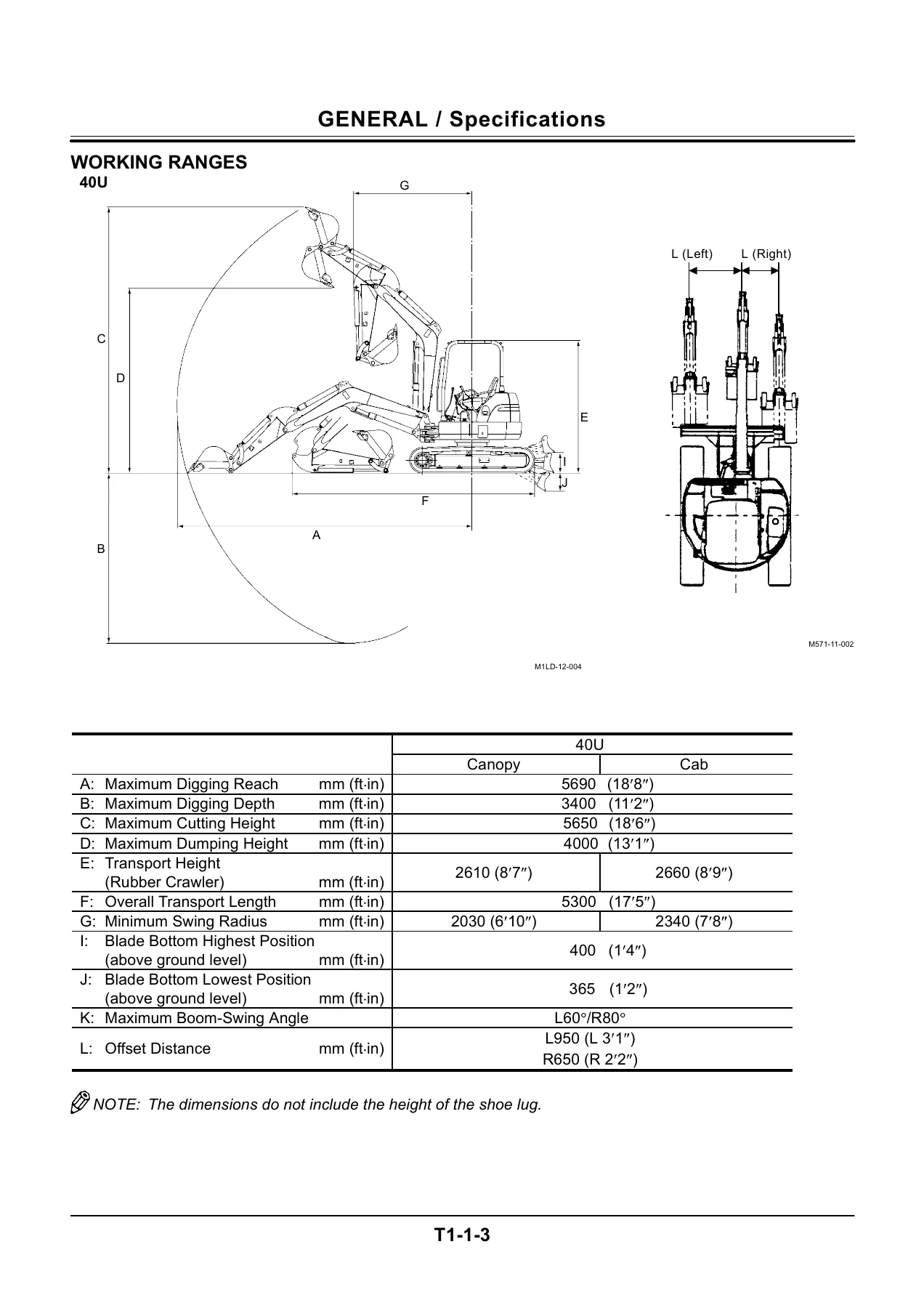
IMAGES PREVIEW
The Troubleshooting chapters are organised by symptom. If the starter does not rotate, if the engine cranks but does not start, if all actuators are slow or unresponsive, if a specific cylinder drifts, if the machine mistracks, if the swing is weak, or if the blade or boom swing fails to operate, the flow charts guide you through the possible causes in a logical order — from the simplest checks (battery voltage, fuse continuity, harness connections) to component-level diagnosis (pilot valve, main relief valve, pressure compensator, shuttle valve, travel motor). The monitor troubleshooting section covers coolant temperature gauge, fuel gauge, alternator indicator, engine oil pressure indicator, overheat indicator, fuel level indicator, buzzer, and hour meter malfunctions.
The Workshop Manual gives you the hands-on procedures. You can remove and install the canopy and counterweight, pull the pump device, control valve, swing device, and pilot valves, and disassemble and reassemble each of them with the correct sequence and torque values. The undercarriage section covers the swing bearing, travel device, center joint, track adjuster, front idler, upper and lower rollers, and rubber crawler removal and installation — including the maintenance standards for sprocket, idler, roller, and track wear. The front attachment section covers the boom, arm, bucket, boom swing, and blade cylinders with complete disassembly and assembly procedures, seal replacement, and torque specifications.
The Engine section at the end is a full engine workshop manual for the Isuzu 4LE2, covering disassembly, inspection and repair, reassembly, lubrication system, cooling system, fuel system, troubleshooting, special tools, service standards, and conversion tables. This means you have the engine service information in the same document as the machine service information — no need to source a separate engine manual for most jobs.
Because this is the Technical and Workshop Manual set rather than just an operator’s manual or a parts catalog, it is the document that professional mechanics, fleet maintenance shops, and serious owner-operators use when they need to go beyond routine maintenance. The specifications and procedures are the ones Hitachi published for these machines, and having them in PDF form means you can print the pages you need for the job, keep them in the shop, and refer to them on a tablet or laptop without worrying about damaging a paper book.
If you own or service a Hitachi Zaxis 40U or 50U excavator, this manual is the most complete technical reference you can have for the machine. It covers both models, the Isuzu 4LE2 engine, and the full hydraulic, electrical, and mechanical systems — from the pilot circuit to the travel device, from performance testing to component overhaul. The document is delivered as an instant PDF download, so you can be reading it minutes after purchase and start the job with the correct information in front of you.
Reviews
There are no reviews yet.