
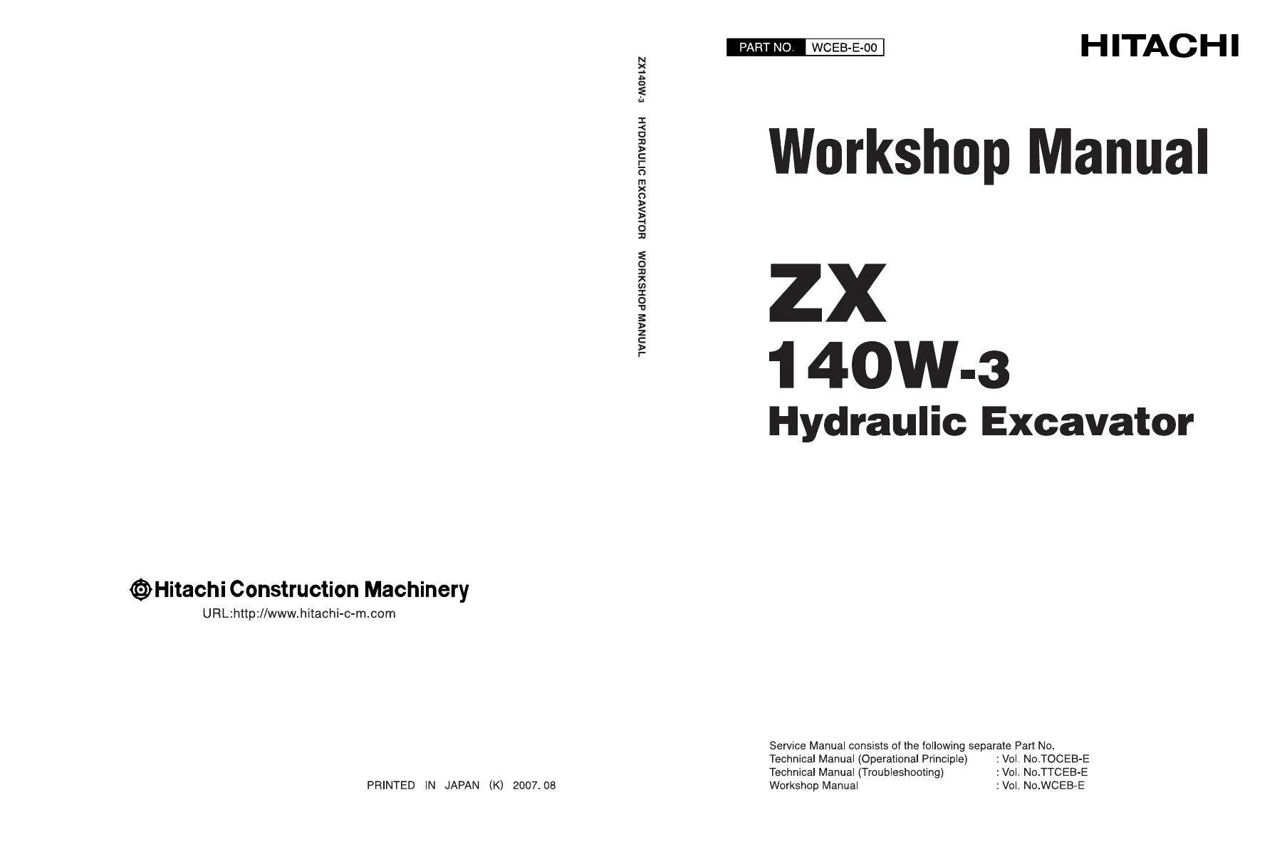
Hitachi ZX140W-3 Wheeled Excavator Workshop Manual – PDF Repair Guide
Original price was: $34.95.$19.95Current price is: $19.95.
Complete Hitachi ZX140W-3 hydraulic excavator workshop manual covering general information, uppertructure, undercarriage and front attachment service procedures with tightening torque specifications and exploded-view disassembly/assembly guidance.
Description
Hitachi ZX140W-3 Wheeled Excavator Workshop Manual
This Hitachi ZX140W-3 Workshop Manual is the maintenance and repair volume for the 140W-3 Hydraulic Excavator. It is written for the experienced technician and provides the technical information needed to carry out maintenance and repair of the machine, together with the tools and devices required, maintenance standards, and removal, installation, disassembly and assembly procedures. If you service, overhaul or rebuild a ZX140W-3 wheeled excavator, this Hitachi ZX140W-3 Workshop Manual PDF gives you the step-by-step procedures, torque figures and component structure details in one searchable document.
File Details
- Manual type: Workshop Manual (maintenance and repair)
- Brand: Hitachi Construction Machinery
- Model: ZX140W-3 / ZX140W-3-AMS
- Machine type: 140W-3 Hydraulic Excavator
- Language: English
- Page count: Approximately 696 pages
- File format: PDF
- Serial number ranges covered: ZX140W-3 up to serial No. 005000 and Serial No. 005001 and up; ZX140W-3-AMS up to serial No. 050000 and Serial No. 050001 and up
Chapters Covered
The ZX140W-3 Workshop Manual is organised into four main sections, each subdivided into groups:
- Section 1 General Information – Group 1 Precautions for Disassembling and Assembling (including maintenance standard terminology), Group 2 Tightening (tightening torque specification, torque chart, piping joint, periodic replacement of parts), Group 3 Painting, Group 4 Bleeding Air from Hydraulic Oil Tank
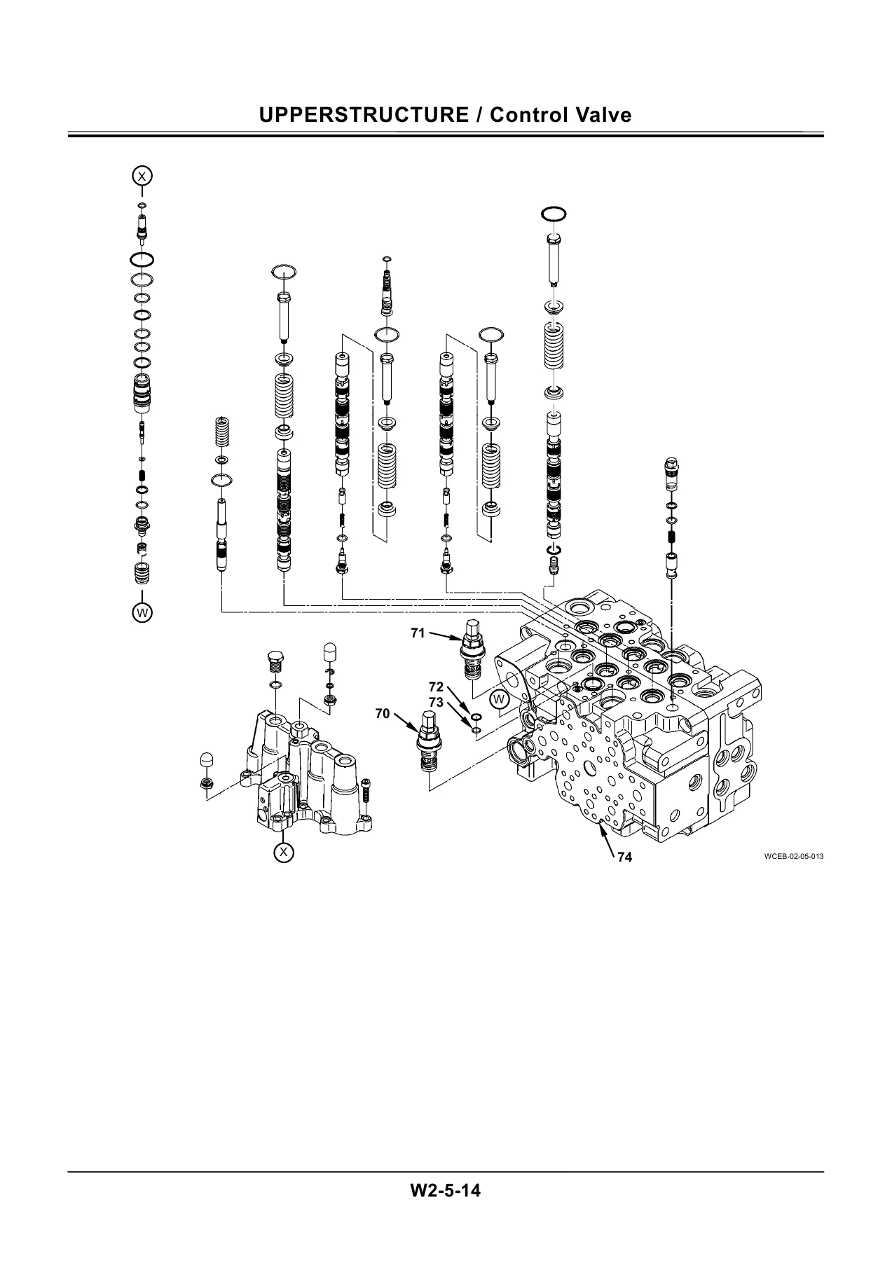
- Section 2 Uppertructure – Group 1 Cab (removal, installation and cab glass dimensions), Group 2 Counterweight, Group 3 Main Frame, Group 4 Pump Device (removal/installation, disassembly, assembly, regulator, pilot pump structure), Group 5 Control Valve (removal/installation, 4-spool and 5-spool side disassembly/assembly, positioning control valve), Group 6 Swing Device (removal/installation, disassembly/assembly, swing motor, valve unit, swing dampener valve, maintenance standard), Group 7 Pilot Valve (front/swing and travel pilot valves), Group 8 Electric Lever, Group 9 Signal Control Valve, Group 10 Shockless Valve (swing and travel), Group 11 Solenoid Valve (3-spool, electric lever, 1-spool units), Group 12 Pilot Shut-Off Solenoid Valve, Group 13 Steering Valve, Group 14 Brake Valve, Group 15 Accumulator Charging Valve
- Section 3 Undercarriage – Group 1 Swing Bearing, Group 2 Travel Motor (disassembly, assembly and brake valve), Group 3 Center Joint (both early and later serial ranges), Group 4 Transmission (both serial ranges), Group 5 Axle (front and rear axle, differential and steering cylinder for both serial ranges), Group 6 Axle Lock Cylinder, Group 7 Operate Check Valve, Group 8 Solenoid Valve, Group 9 Transmission Changeover Solenoid Valve, Group 10 Propeller Shaft
- Section 4 Front Attachment – Group 1 Front Attachment (monoblock boom and 2-piece boom, maintenance standard, standard dimensions for arm and bucket connection), Group 2 Cylinder (boom, arm, bucket, positioning, outrigger and blade cylinders), Group 3 Hose Rupture Valve (arm, boom and positioning cylinder valves), Group 4 Operate Check Valve (for blade and outrigger)
Beyond the chapter listing, this Hitachi ZX140W-3 Workshop Manual is built around real repair work: it opens with safety, disassembly and assembly precautions, tightening torque specifications, a torque chart with bolt types, piping joint procedures, seal tape and hose clamp torque data, and a periodic replacement parts schedule. From there it moves system by system through the uppertructure, undercarriage and front attachment, giving removal and installation sequences, disassembly and assembly procedures, exploded-view figures, cross-section illustrations and torque figures for every major component.
What This ZX140W-3 Workshop Manual Covers in Practice
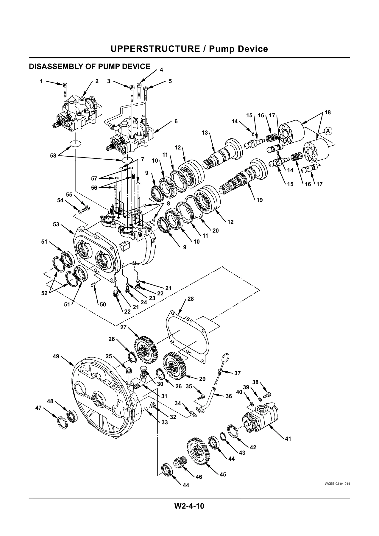
The pump device section takes the technician through removal from the engine, complete disassembly and re-assembly of the pump casing, shafts, bearings and regulators, along with the structure of the pilot pump. The control valve group covers removal and installation, split-flange and socket bolt torque, 4-spool and 5-spool side disassembly and assembly, plus the positioning control valve. The swing device chapter documents the swing motor, valve unit, swing dampener valve and maintenance standard values, so bearing clearances, plunger clearances and rotor bore limits can be checked against the book.
The undercarriage section handles travel motors, brake valves, center joints and transmissions for both serial ranges listed, front and rear axles including differential and steering cylinder, axle lock cylinder, operate check valves and the propeller shaft. Wheeled excavator driveline work is where a ZX140W-3 Workshop Manual PDF earns its keep, and this one carries the disassembly, assembly, torque and service limit data across all of those assemblies.
The front attachment section covers the monoblock boom and the 2-piece boom front attachment removal and installation, the maintenance standard for pins, bushings and bosses, standard dimensions for the arm, bucket and boom connections, and the disassembly/assembly procedures for the boom, arm, bucket, positioning, outrigger and blade cylinders, including piston nut torque values and seal installation directions. Hose rupture valve and operate check valve structure and servicing round out the attachment coverage.
Why Technicians Use This Hitachi ZX140W-3 Workshop Manual
Correct torque values, seal orientation, bearing preload, press-in dimensions and service limits decide whether a repair lasts or comes back. The Hitachi ZX140W-3 Workshop Manual supplies those figures in the same pages as the procedure, so the technician does not have to guess or look elsewhere. Maintenance standard chapters list standard dimensions and allowable limits for pins, bushings, sliding surfaces, floating seals, friction plates and pistons, with the remedy to apply when a limit is exceeded. Whether you are resealing a boom cylinder, rebuilding a travel motor, splitting the control valve, refreshing the swing device or setting up the swing bearing and counterweight on the main frame, the ZX140W-3 Workshop Manual PDF keeps the sequence and the numbers together.
This manual also suits workshops that maintain a mixed fleet, because the serial-number break points for the ZX140W-3 and ZX140W-3-AMS are called out inside the undercarriage procedures where center joint, transmission and axle methods change. That level of detail is what separates a usable wheeled excavator service document from a generic parts list.
Delivery
IMAGES PREVIEW
The Hitachi ZX140W-3 Wheeled Excavator Workshop Manual is delivered as an instant PDF download – no shipping, no waiting for a courier. Use it on a laptop in the workshop, on a tablet next to the machine, or print the pages you need for the job at hand. The file is a complete reproduction of the manual’s technical content so you can search, zoom and follow procedures page by page.
Start Your Next ZX140W-3 Repair With the Right Reference
With this Hitachi ZX140W-3 Workshop Manual PDF you can carry out maintenance and repair of the ZX140W-3 hydraulic excavator from the first precaution through to the final torque check: remove and install the cab and counterweight, service the pump device and control valve, rebuild the swing device and travel motors, work through the center joint, transmission, axles and propeller shaft, and overhaul the cylinders on the front attachment. Having the correct procedures and specifications on hand reduces the risk of damaged seals, incorrect bearing preload, stripped threads and repeat failures, and it helps keep the machine working the way it was designed to. Download the manual now and put the manufacturer’s own service information to work in your workshop.


Reviews
There are no reviews yet.