
Hitachi ZX350LC-7 & ZX350LCN-7 Excavator Technical Manual – Operational Principle PDF (TODD750-EN-00, 2019)
Original price was: $44.95.$26.95Current price is: $26.95.
Official Hitachi Technical Manual Operational Principle for the ZX350LC-7 and ZX350LCN-7 hydraulic excavators. Covers controller logic, engine and hydraulic systems, component operation, and electrical circuits. 479-page PDF, document TODD750-EN-00, published 2019.
Description
Hitachi ZX350LC-7 & ZX350LCN-7 Technical Manual – Operational Principle
This is the Technical Manual Operational Principle for the Hitachi ZX350LC-7 and Hitachi ZX350LCN-7 hydraulic excavators. Published by Hitachi Construction Machinery Co., Ltd. under document number TODD750-EN-00 (2019), it explains how the machine’s controllers, systems, and components actually function — not just what to replace, but the operating logic behind every circuit.
If you maintain, diagnose, or repair a ZX350LC-7 or ZX350LCN-7, this manual is the reference that tells you why a system behaves the way it does. It is the operational-principle companion to the workshop and troubleshooting manuals, and it stands alone as a complete technical explanation of the machine.
File Details
- Manual type: Technical Manual — Operational Principle
- Brand: Hitachi Construction Machinery
- Models covered: ZX350LC-7, ZX350LCN-7 (including 2-piece boom specification)
- Document number: TODD750-EN-00
- Publication date: 2019 (15/11/2019)
- Language: English
- Page count: 479
- File format: PDF
Chapters Covered
The manual is organised into three sections, each with numbered groups. The full contents as printed:
- Section 1 — General
- Specifications (ZX350LC-7, ZX350LCN-7, and 2-piece boom)
- Working Ranges
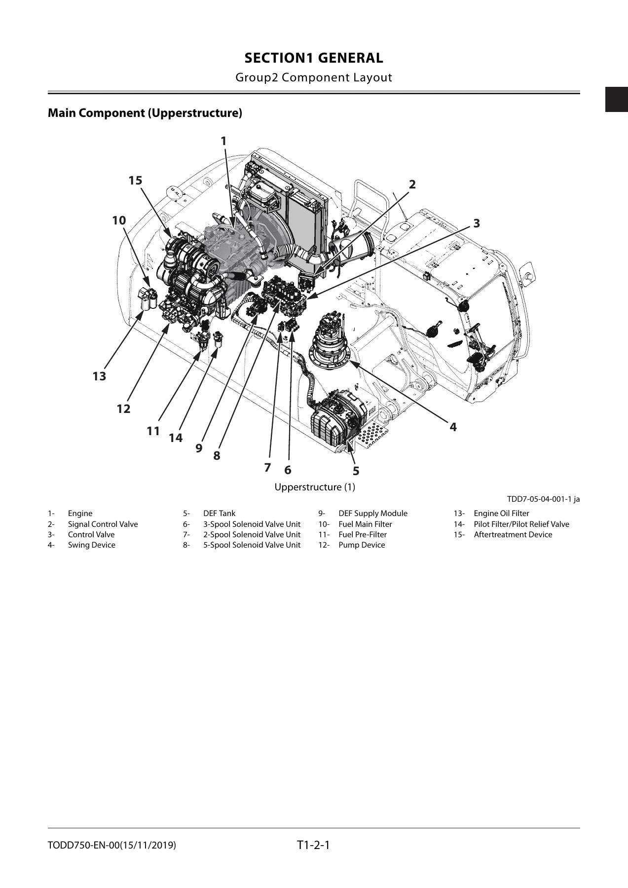
- Component Layout (upperstructure, undercarriage, front attachment, electrical system, engine, aftertreatment, pump device, control valve, swing device, travel device, solenoid valve units, DEF tank, DEF supply module)
- Component Specifications (engine, engine accessories, hydraulic components, electrical components)
- Section 2 — System
- Controller (outline, CAN circuit)
- Control System (engine control, pump control, valve control, work mode, alarms, auto shut-down, aftertreatment regeneration control)
- Engine System (ECM system, fuel injection, EGR, preheating, variable turbocharger, Urea SCR, DEF controls, aftertreatment device)
- Hydraulic System (pilot circuit, main circuit, flow combiner, relief, digging regenerative, arm regenerative cut, breaker/pulverizer/crusher circuits)
- Electrical System (main circuit, CAN, starting, charging, pilot shut-off, auto shut-down, engine stop, monitor, security, aerial angle, seat belt, radio, air conditioner, work lights, wiper, cab light)
- Section 3 — Component Operation
- Pump Device (main pump, regulator, control functions, pilot pump, pressure sensors)
- Swing Device (reduction gear, motor, parking brake, valve unit, relief valve, dampener valve)
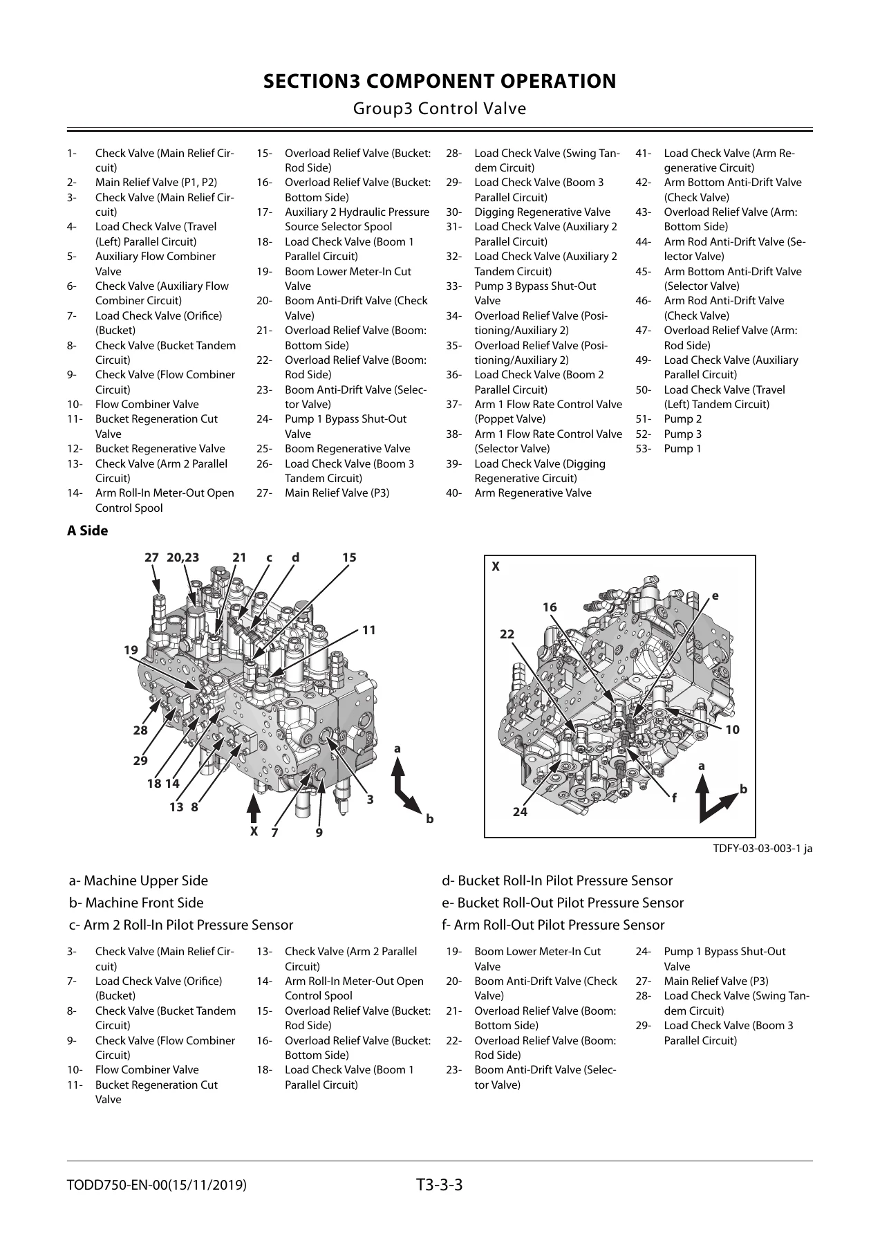
- Control Valve (main relief, overload relief, regenerative valves, anti-drift, flow rate control, digging regenerative, boom lower meter-in cut, auxiliary flow combiner, bypass shut-out)
- Pilot Valve (front attachment/swing, travel, auxiliary 1 and positioning/auxiliary 2, shockless function)
- Travel Device (motor, reduction gear, parking brake, brake valve, travel mode control)
- Signal Control Valve (shuttle valves, shockless valve, flow rate control valves, flow combiner control spool, swing parking brake release spool)
- Others (Upperstructure) — pilot shut-off solenoid valve, solenoid valve units, proportional and ON/OFF solenoid valves, hose rupture valve, pilot relief valve, recirculation valve
- Others (Undercarriage) — swing bearing, center joint, track adjuster
In plain terms, this manual walks through the entire machine from the controllers outward. The Control System group explains the logic that MC uses to command the engine, pumps, and valves — engine protection, auto-idle, ECO mode, travel HP mode, pump flow rate control, power digging, digging regenerative control, and aftertreatment regeneration. The Engine System group covers ECM fuel injection strategy, EGR, variable turbocharger, Urea SCR, and DEF management. The Hydraulic System group lays out the pilot and main circuits, flow combiner behaviour, relief, regeneration, and the optional breaker/pulverizer/crusher circuits. Component Operation then breaks down each major unit — pump regulator, swing motor, control valve internals, pilot valve, travel motor, signal control valve — explaining exactly how each valve shifts, what pressure acts where, and how the result is achieved.
Every page is built to be read by an experienced technician: regulators are shown in their neutral, increasing, and decreasing states; control valve functions are described step by step; solenoid valve operation is explained with pressure-balance logic. This is the level of detail needed to understand a symptom rather than simply replace parts.
What This Manual Enables You To Do
- Trace engine control behaviour from MC signal through ECM to fuel injection, including ECO, auto-idle, engine protection, and travel HP modes
- Understand pump control — speed sensing, torque decrease, flow rate control, flow rate limit control — and how the regulators respond to every command pressure
- Follow the complete pilot and main hydraulic circuits, including flow combiner, relief, digging regenerative, arm regenerative cut, and the optional breaker/pulverizer/crusher circuits
- Diagnose valve behaviour by understanding exactly which spool moves, which pilot pressure acts, and what the expected result is
- Understand the Urea SCR system, DEF injection, defrosting, thermal control, and aftertreatment regeneration logic
- Read the electrical system by function — starting, charging, pilot shut-off, auto shut-down, monitor, security, work lights, wiper, and more
- Understand component internals such as the pump regulator, swing dampener valve, travel brake valve, hose rupture valve, and signal control valve
Why This Manual Matters
The ZX350LC-7 and ZX350LCN-7 are controlled by a network of MC, ECM, DCU, and dedicated controllers, with pump and valve behaviour that changes according to operating mode, temperature, load, and attachment. Guessing at that behaviour leads to misdiagnosis and unnecessary parts replacement. This manual gives you the actual operating logic: which sensor feeds which controller, which solenoid is energised under which condition, how the regulator balances pump control pressure against delivery pressure, and how each valve opens and closes.
For a technician working on these machines, the operational principle is the foundation for correct troubleshooting. It tells you what the machine is supposed to do before you decide it is doing something wrong.
Delivery
Instant PDF download after payment — no shipping, no waiting. The file works on any device (PC, Mac, tablet, smartphone) and every page is printable for use in the workshop. Keep a copy on your service laptop, print the sections you need for the job at hand, and have the full operational principle available whenever a ZX350LC-7 or ZX350LCN-7 needs diagnosis, repair, or a proper understanding of how it works.
Reviews
There are no reviews yet.