
Hitachi ZX85USB-5A Hydraulic Excavator Technical Manual Troubleshooting TTDEE-EN-00
Original price was: $44.95.$26.95Current price is: $26.95.
Complete Hitachi ZX85USB-5A hydraulic excavator troubleshooting technical manual (TTDEE-EN-00). Covers operational performance testing, fault code diagnostics, controller systems, hydraulic and electrical troubleshooting, and air conditioner service for the ZX85USB-5A.
Description
Hitachi ZX85USB-5A Technical Manual Troubleshooting – TTDEE-EN-00
This is the Hitachi ZX85USB-5A Hydraulic Excavator Technical Manual Troubleshooting, publication number TTDEE-EN-00. It is the dedicated diagnostic and performance testing volume from the Hitachi Technical Manual set — the book a technician reaches for when a ZX85USB-5A is not running right and the fault has to be found, measured, and corrected rather than guessed at.
Where the Workshop Manual covers removal and installation, this ZX85USB-5A troubleshooting manual is built around measurement and diagnosis: how to test each circuit against a published standard, how to read the machine’s own controllers, how to interpret fault codes, and how to work backwards from an operator’s complaint to a specific failed component.
File Details
- Manual type: Technical Manual (Troubleshooting)
- Brand: Hitachi Construction Machinery
- Model: ZX85USB-5A hydraulic excavator
- Publication number: TTDEE-EN-00
- Revision date shown: 20180727
- Language: English
- Format: PDF
- Length: 372 pages
Chapters Covered
The manual is organised into two large divisions, each broken into numbered groups:
Section 4 — Operational Performance Test
- Group 1 — Introduction: purpose of performance testing, test area setup, precautions, making precise measurements, preparation for performance tests
- Group 2 — Standard: operational performance standard tables, Main Pump 1 & 2 P-Q diagram, Main Pump 3 P-Q diagram, sensor activating range, MPDr. monitor indicating values (ECU, MC, wiper/light controller)
- Group 3 — Engine Test: engine speed measurement across all modes (slow idle, fast idle, relief, ECO, Travel HP, auto-idle, warming-up), lubricant consumption
- Group 4 — Excavator Test: travel speed, track revolution speed, mistrack check, travel parking leakage, swing speed, swing function drift check, swing motor leakage, maximum swingable slant angle, swing bearing play, hydraulic cylinder cycle time, dig function drift check, control lever operating force, control lever stroke, combined boom raise/swing, combined boom raise/arm roll-in, front attachment connecting part clearance
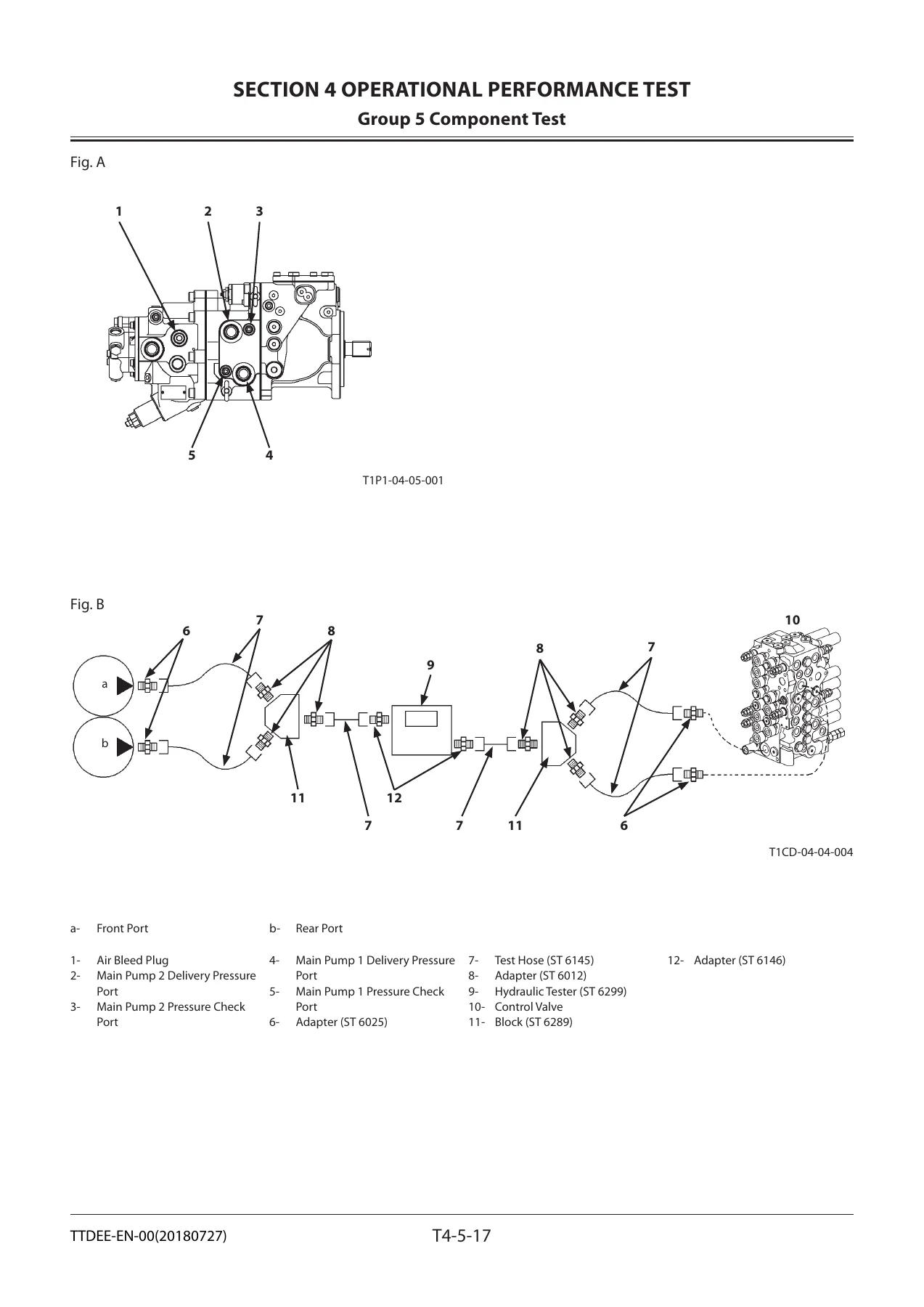
- Group 5 — Component Test: primary pilot pressure and adjustment, secondary pilot pressure, solenoid valve set pressure and adjustment, main pump delivery pressure, main relief valve set pressure and adjustment, swing relief valve set pressure and adjustment, travel relief valve set pressure and adjustment, overload relief valve set pressure and adjustment, Main Pumps 1 & 2 flow rate, Main Pump 3 flow rate, swing motor drainage, travel motor drainage
Section 5 — Troubleshooting
- Group 1 — Diagnosing Procedure: systematic diagnosis procedure, electrical system inspection, precautions for inspection and maintenance, disconnecting connectors, fuse inspection, fusible link and slow blow fuse inspection, battery voltage check, alternator check, continuity checks, voltage and current measurement, check by false signal, test harnesses
- Group 2 — Monitor: service menu operation, troubleshooting display, monitoring screen, controller version, issued warning record, operation hour meters, communication terminal status, machine setting, monitor setting, hour meter and fuel gauge inspection, fuel gauge and coolant temperature gauge values
- Group 3 — e-Service: operation data list, snapshot data, communication system overview
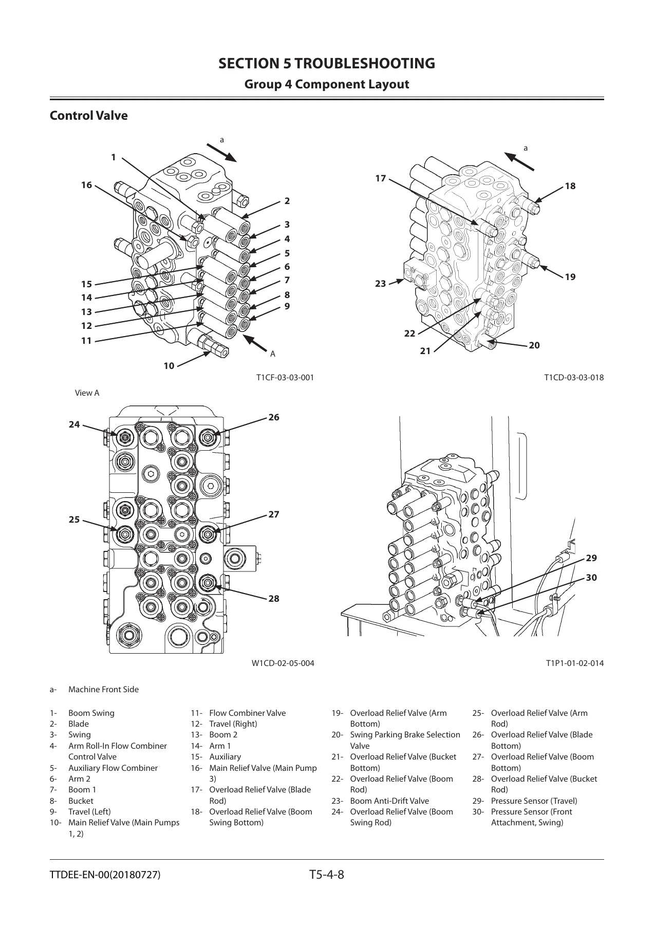
- Group 4 — Component Layout: main component locations, electrical system (overview, rear tray, switch panel, around battery), engine, control valve, pump device, swing device, travel device, components inside the control valve
- Group 5 — Troubleshooting A (fault-code based diagnosis): MC fault code list, ECU fault code list, monitor controller fault codes, air conditioner controller fault codes, communication terminal fault codes, CAN0 and CAN1 harness checks, individual fault code diagnosis procedures including 11000–11003, 11006–11010, 11100, 11101, 11304, 11307, 11401, 11407, 11459, 20011, 20113, 13304, 13310, 13311, 20100–20114, air conditioner codes 11–92
- Group 6 — Troubleshooting B (symptom-based diagnosis): relationship between machine trouble symptoms and related parts, correlation between trouble symptoms and part failures, engine system troubleshooting (starter will not rotate, engine will not start, power mode not shifting, ECO mode, Travel HP mode, auto-idle, auto shut-down, overheating), all-actuator system troubleshooting, front attachment system troubleshooting, swing system troubleshooting, travel system troubleshooting, blade system troubleshooting, other system troubleshooting (work light, boom light, wiper, washer), exchange inspection method, emergency boom lowering procedures with and without hose rupture valve
- Group 7 — Air Conditioner: system outline, functions of main parts, troubleshooting, air conditioner controller fault code list, fault codes 11–22 and 43–92, work after replacing components, refilling compressor oil, charging air conditioner with refrigerant, hose and pipe tightening torque
What This Manual Gives You
The ZX85USB-5A Technical Manual Troubleshooting is unusual among excavator service literature because it separates two things most manuals blend together. The Operational Performance Test section gives you a numeric baseline — the pressures, flow rates, cycle times, drift limits, lever forces, and engine speeds that a healthy ZX85USB-5A should produce. The Troubleshooting section then gives you the logic to find out why a real machine is not producing them.
That combination matters because hydraulic diagnostics on a compact excavator are easy to get wrong. Replacing a pump when the real problem is a clogged pilot filter, or condemning a swing motor when the parking brake selection valve is stuck, is expensive. This manual is structured so the technician measures first and replaces second. It ships with the P-Q diagrams for all three main pumps, the sensor activating ranges, and the MPDr. monitor reference values needed to read live machine data against a known standard.
The fault code coverage is extensive. It documents both the MC (Main Controller) codes and the ECU codes, and it includes a dedicated list for the monitor controller, air conditioner controller, and the communication terminal. Each code comes with the fault description, probable cause, the symptom the operator would actually notice, and the recommended remedy. For fault codes that require measurement rather than part-swapping, the manual supplies the pin numbers and expected voltage or resistance at each step.
For symptoms that do not throw a code, the manual provides a different kind of tool: a symptom-to-part correlation table. If the machine mistracks only during combined travel and front attachment operation, the table points at the flow combiner valve. If the boom hesitates before rising, it points at the load check valve or the boom anti-drift valve. This is the practical knowledge that saves diagnostic hours.
Who This Manual Is For
This Hitachi ZX85USB-5A technical manual is written for the experienced technician, as Hitachi states in its opening note to the reader. It assumes familiarity with hydraulic and electrical test equipment and with the general layout of the machine. It is not an operator’s manual and does not cover basic operation, daily checks, or safety procedures in the depth the operator’s manual does, although the electrical system inspection section does contain important safety and handling precautions.
It is also useful for the owner-operator who wants to understand what a dealer technician is actually doing, or who wants to run their own performance tests before committing to a repair. The fault code lists alone are worth having on hand, because they tell you whether the machine is reporting a genuine component failure or an intermittent connection that will disappear on its own.
Related Hitachi Documentation
Hitachi divides its service literature into three volumes for this machine. The Technical Manual covers operation and activation of devices and systems, operational performance tests, and troubleshooting. The Workshop Manual covers maintenance and repair, tools, maintenance standards, and removal/installation and assembly/disassembly procedures. The Engine Manual covers engine redelivery, operation, maintenance, troubleshooting, and disassembly. This listing is for the Technical Manual Troubleshooting volume only. The additional diagrams listed at the back of the manual — electrical circuit diagrams, cab harness, main harness, engine harness, monitor harness, hydraulic circuit diagrams for monoblock and 2-piece boom, and the AFL electrical and hydraulic diagram variants — are referenced as attached drawings.
Diagnose, Measure, Repair — With the Right Numbers in Front of You
What this manual enables is straightforward: you can run a full operational performance test on a ZX85USB-5A and compare the results to Hitachi’s published standard. You can read every fault code the machine’s controllers produce, understand what each one means, and follow the prescribed diagnostic path. You can trace a symptom from the operator’s seat to the specific valve, sensor, solenoid, relay, or harness circuit responsible. You can set relief pressures, adjust P-Q control, and confirm pump flow rates against spec. You can service and recharge the air conditioning system, including the correct procedures after compressor replacement.
Doing the job without correct procedures and specifications is how machines get over-pressured, how pumps get replaced unnecessarily, and how hydraulic systems get contaminated. The values in this manual are the ones the machine was built to meet. Guessing at them, or substituting numbers from a different model, risks damaging the excavator or creating a safety hazard that shows up later.
IMAGES PREVIEW
Delivery: This is a digital PDF manual, available for instant download after payment. There is no physical shipment, no shipping cost, and no waiting. The file can be viewed on any device — desktop, laptop, tablet, or smartphone — and individual pages can be printed for use in the workshop where a screen is impractical. Keep it on a phone in the cab, or print the performance standard tables and fault code lists and keep them in the toolbox.


Reviews
There are no reviews yet.