
Hitachi ZX870-5G Series Hydraulic Excavator Workshop Manual – ZX870-5G, 870LC-5G, 870H-5G, 870LCH-5G, 870LCR-5G PDF
Original price was: $39.95.$24.95Current price is: $24.95.
Complete Hitachi workshop manual for the ZX870-5G series hydraulic excavator covering ZX870-5G, 870LC-5G, 870H-5G, 870LCH-5G and 870LCR-5G – disassembly, assembly, removal, installation, maintenance standards and the full Isuzu 6WG1TQA engine section.
Description
Hitachi ZX870-5G Series Hydraulic Excavator Workshop Manual
This is the full workshop manual for the Hitachi ZX870-5G series hydraulic excavator, published under document number WJBE-EN. It is the removal/installation and disassembly/assembly volume of the Hitachi service literature set, written for the experienced technician working on the ZX870-5G, ZX870LC-5G, ZX870H-5G, ZX870LCH-5G and ZX870LCR-5G machines. Where the Technical Manual (Operational Principle) explains how the systems work and the Technical Manual (Troubleshooting) diagnoses faults, this workshop manual is the book you have open on the bench: it tells you how a component comes off the machine, how it comes apart, what the wear limits are, and how it goes back together at the correct torque.
File Details
- Manual type: Workshop Manual (Removal and Installation, Disassembly and Assembly)
- Brand / manufacturer: Hitachi Construction Machinery Co., Ltd.
- Models covered: ZX 870-5G, 870LC-5G, 870H-5G, 870LCH-5G, 870LCR-5G
- Document number: WJBE-EN (Vol. No. WJBE-EN)
- Language: English
- Page count: 998 pages
- File format: PDF
- Copyright date shown: 2012
Chapters Covered
The Hitachi ZX870-5G workshop manual is organised into six numbered sections, each broken into groups:
- Section 1 – General: Precautions for Disassembling and Assembling, Tightening Torque (bolts, nuts, piping joints, split flange, quick coupling, screw-in connections), Painting, Bleeding Air (hydraulic oil tank, hydraulic system, fuel system, radiator), Pressure Release Procedure, Preparation before Inspection and Maintenance
- Section 2 – Maintenance Standard: Upperstructure (main pump, fan pump, swing motor), Undercarriage (travel device, sprocket, center joint, front idler, upper roller, lower roller, track), Front Attachment (pin and bushing, side cutter, point, arm and bucket connection dimensions, arm and boom connection dimensions, cylinder)
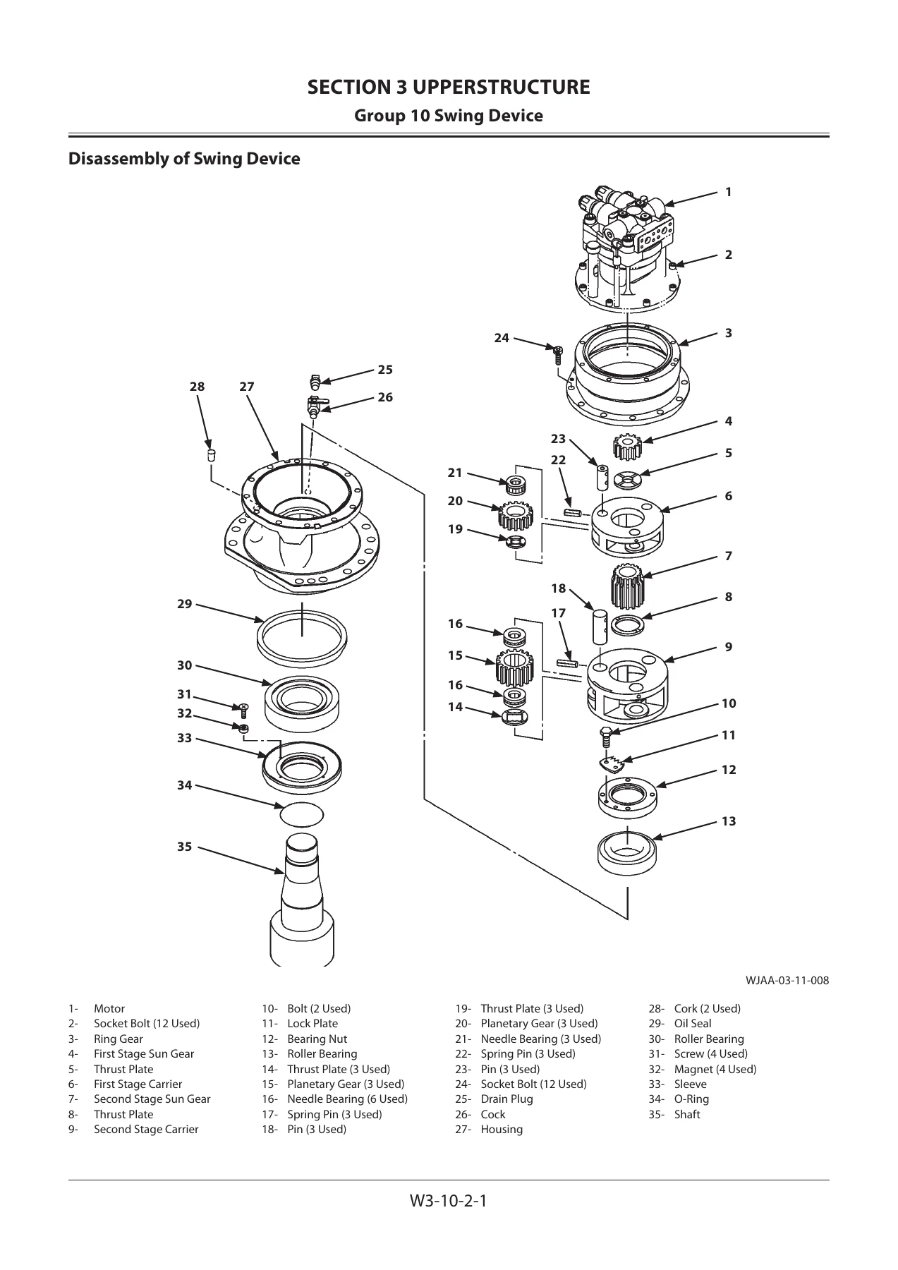
- Section 3 – Upperstructure: Cab, Swing Counterweight, Main Frame, Engine, Radiator Assembly (radiator, intercooler, oil cooler), Hydraulic Oil Tank, Fuel Tank, Pump Device (pump transmission, main pump, regulator, fan pump, pilot pump), Control Valve (4-spool and 5-spool sides, valve unit), Swing Device, Pilot Valve (left, right, travel), Solenoid Valve (pilot shut-off, 4-spool and 2-spool units), Signal Control Valve, Shockless Valve, Fan Valve, Fan Motor
- Section 4 – Undercarriage: Swing Bearing, Travel Device (travel motor, brake valve, floating seal precautions), Center Joint, Track Adjuster, Front Idler, Upper and Lower Rollers, Track
- Section 5 – Front Attachment: Bucket, Arm, Boom, bushing removal and installation, Boom Cylinder, Arm Cylinder, Bucket Cylinder
- Section 6 – Engine and Accessory: General Information, Service Information (lubrication, fuel, cooling, valve clearance, compression pressure, recommended lubricants), Engine Mechanical, Engine Cooling, Engine Fuel, Starting and Charging, Engine Lubrication, Engine Induction
Read as a whole, this workshop manual gives a technician the complete mechanical route through the ZX870-5G class machine – from lifting the cab and unbolting the 13,400 kg counterweight, through splitting the pump transmission and rebuilding the main pump, right down to reseating a floating seal in a lower roller. The maintenance standard section is what makes it practical day to day: it carries the standard and allowable-limit dimensions for the pump plungers and cylinder block bores, the servo piston clearances, sprocket and idler wear limits, track link and bushing measurements, and the pin and bushing diameters for every joint on the boom, arm and bucket.
What You Can Actually Do With It
Every major assembly on the machine is covered with a numbered procedure rather than a general description. The manual states component weights before you rig them – the counterweight at 13,400 kg (29,600 lb), the main frame at 19,200 kg (42,400 lb), the travel device at 1,090 kg (2,410 lb), the pump device at 755 kg (1,670 lb), the control valve at 430 kg (950 lb), the swing device at 405 kg (895 lb) each and the hydraulic oil tank at 450 kg (995 lb) – and it tells you where the lifting brackets, eyebolt holes and shackle points are for each one. It also flags the fixings that carry thread locking compound and must be degreased and re-treated, and the bolts that must not be reused.
The pump section goes all the way in. You get removal of the complete pump device, separation of the main pumps, pilot pump, fan pump and pump transmission, then full disassembly and assembly of the pump transmission with its cartridges, gears, ball bearings and oil seals, followed by main pump disassembly covering the rotor, valve plate, swash plate, servo piston, stoppers, shaft, roller and needle bearings, and the regulator with its sleeve, spool, cylinder, spring and solenoid valve block. Torque values are given throughout – socket bolts at 540 N·m (54 kgf·m), main pump port block bolts at 550 N·m (55 kgf·m), regulator bolts at 30 to 65 N·m depending on size.
The control valve chapter deals with both housings, the 4-spool side and the 5-spool side, and covers the individual cartridges: load check valves, arm and bucket regeneration cut valves, flow combiner valves, bypass shut-out valves, boost check valves, flow rate control valves, boom 2 anti-drift valve, arm rod anti-drift valve, main relief valve, overload relief valves and the auxiliary flow combiner valve. Where a valve must not be disturbed because its setting would change, the manual says so plainly.
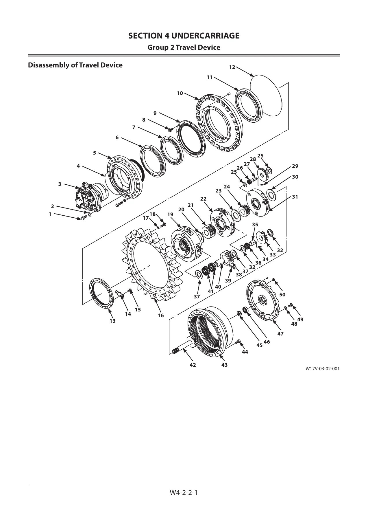
Travel is handled as two separate jobs – the travel device and the travel motor. The travel device section walks through the floating seal, roller bearings, drum, sprocket, bearing nut and lock plate, and the three planetary stages with their carriers, sun gears, planetary gears, thrust plates, needle bearings, pins and spring pins. The travel motor section covers the brake valve with its relief valves, spools, check valves and caps, plus the brake piston, friction and separator plates, rotor, plungers, retainer, swash plate, shaft and oil seal. A dedicated floating seal procedure explains matched seal ring sets, O-ring seating, twist and bend checks, and how to verify the sliding surface and seal mating surface are parallel.
Undercarriage, Attachment and Hydraulics
The undercarriage section covers the swing bearing down to individual balls and supports, center joint body and spindle with bushing replacement, the track adjuster with its spring compression procedure and the special tooling required, the front idler with its axle, bearings, bushings and yoke, the upper and lower rollers with their bushings and floating seals, and the track itself including master pin removal and installation with the hydraulic master pin tool.
The front attachment section gives you the bucket, arm and boom removal sequences with weights, the shim and clearance figures for the bucket and arm joints, the bushing removal and installation procedure with the correct pressing plates listed per position, and complete disassembly and assembly of the boom, arm and bucket cylinders – cylinder head, bushing, retaining ring, U-ring, backup rings, wiper ring, piston, slide rings, seal ring, cushion bearing, nut, steel ball and set screw, with the nut torques stated for each cylinder size.
Hydraulic and pilot side, the manual covers the pilot valves, the pilot shut-off solenoid valve, the 4-spool and 2-spool solenoid valve units, the signal control valve, shockless valve, fan valves and the oil cooler and radiator fan motors.
Engine Section
The engine portion of this workshop manual covers the Isuzu 6WG1TQA diesel engine fitted to the ZX870-5G class. It includes general repair instructions, illustration arrow conventions, abbreviations, the angular tightening method for high-tensile fasteners, standard bolt torque tables, recommended thread locking agents, main data and specifications, performance curve, engine external drawing, service standards, torque specifications, special tools, troubleshooting by symptom, lubricant and sealant application charts, and then full mechanical coverage of fan center, turbocharger, exhaust manifold, inlet manifold, water pump, alternator, oil cooler, injection pump, coupling assembly, cylinder head, rocker arm and shaft assembly, camshaft, timing gears, flywheel housing, oil pan, piston, crankshaft, crank pulley, flywheel and cylinder block. Separate sub-sections handle engine cooling, engine fuel including two-stage injection nozzle holders, starting and charging, engine lubrication, and engine induction.
Who This Manual Is For
This Hitachi ZX870-5G series workshop manual suits the heavy equipment mechanic, the fleet workshop, the independent repair shop and the technically minded owner who needs the real removal, installation, disassembly and assembly procedures with the manufacturer’s own maintenance standards rather than a generic guide. Because it covers the five model variants in the series, it also works for anyone maintaining a mixed fleet of ZX870-5G, ZX870LC-5G, ZX870H-5G, ZX870LCH-5G and ZX870LCR-5G machines – the track tension specification differs between the standard and long undercarriage variants, and the manual states both.
Working from the correct procedures and wear limits is what separates a repair that lasts from one that comes back. Measuring plunger-to-bore clearance, checking floating seal seating, tightening a bearing nut to the right torque and then re-checking play, or confirming a cylinder nut is crimped after staking – these are the details that determine whether a component survives. This manual supplies them for this machine specifically.
Get It and Get Started
The Hitachi ZX870-5G series hydraulic excavator workshop manual is delivered as an instant PDF download. There is no shipping and nothing to wait for – complete checkout and the file is available immediately. It opens on a laptop, tablet or phone, and any page can be printed and taken to the machine, which is exactly how a workshop manual gets used. If you are rebuilding a pump, resealing a travel motor, replacing a swing bearing or pulling a cylinder apart on a ZX870-5G, ZX870LC-5G, ZX870H-5G, ZX870LCH-5G or ZX870LCR-5G, this is the document to have beside you.
Reviews
There are no reviews yet.