★ TRUSTED BY 321,897+ PROFESSIONALS WORLDWIDE
🏒
Trusted Business
Verified & Licensed
πŸ›‘οΈ
Virus Free Files
100% Safe Downloads
πŸ”’
Secure Payment
SSL Protected
⚑
Instant Delivery
Available Immediately
Sale!

Hitachi ZX450-3 ZX470H-3 ZX500LC-3 ZX520LCH-3 Hydraulic Excavator Service Manual – Technical & Workshop Manual PDF

Original price was: $44.95.Current price is: $26.95.

Complete Hitachi service manual for ZX450-3, ZX450LC-3, ZX470H-3, ZX470LCH-3, ZX500LC-3 and ZX520LCH-3 hydraulic excavators. Covers operational principles, troubleshooting, workshop repair, hydraulic and electrical systems, engine, pump device, control valve, swing and travel devices, front attachment, and full specifications.

⚑
Instant PDF Download
Available immediately
πŸ’Ύ
Save to Your Device
Download & keep forever
πŸ›‘οΈ
Antivirus Scanned
100% virus-free
🌍
Trusted Worldwide
175,000+ customers

Description

The Hitachi ZX450-3 ZX470H-3 ZX500LC-3 ZX520LCH-3 Hydraulic Excavator Service Manual is a comprehensive PDF covering six Hitachi excavator models: ZX450-3, ZX450LC-3, ZX470H-3, ZX470LCH-3, ZX500LC-3, and ZX520LCH-3. This combined Technical Manual and Workshop Manual gives technicians, mechanics, and service personnel the operational principles, troubleshooting procedures, and step-by-step repair instructions needed to maintain and overhaul these machines. Whether you are diagnosing a hydraulic fault, rebuilding a travel motor, or adjusting engine speed settings, this Hitachi excavator service manual delivers the detailed information required.

File Details

  • Manual Type: Technical Manual (Operational Principle & Troubleshooting) + Workshop Manual
  • Brand: Hitachi
  • Models Covered: ZX450-3, ZX450LC-3, ZX470H-3, ZX470LCH-3, ZX500LC-3, ZX520LCH-3
  • Language: English
  • Page Count: 1392 pages
  • File Format: PDF
  • Revision Date: 29 April 2010
  • Document Numbers: TO1J1-E (Operational Principle), TT1J1-E (Troubleshooting), W1J1-E (Workshop Manual)

Chapters Covered

The Hitachi ZX450-3 ZX470H-3 ZX500LC-3 ZX520LCH-3 Hydraulic Excavator Service Manual is organized into clearly defined sections that span the full range of service and repair topics.

Technical Manual (Operational Principle)

  • Section 1 General: Specifications, Component Layout, Component Specifications
  • Section 2 System: Controller (MCF, ECM, ICF, Monitor Unit, CAN), Control System (Engine Control, Pump Control, Valve Control), ECM System (Fuel Injection, EGR, Engine Start/Stop), Hydraulic System (Pilot Circuit, Main Circuit), Electrical System (Main Circuit, Starting, Charging, Pilot Shut-Off, Security)
  • Section 3 Component Operation: Pump Device, Swing Device, Control Valve, Pilot Valve, Travel Device, Signal Control Valve, Others (Upperstructure and Undercarriage)

Technical Manual (Troubleshooting)

  • Section 4 Operational Performance Test: Introduction, Standard, Engine Test, Excavator Test, Component Test
  • Section 5 Troubleshooting: Diagnosing Procedure, Monitor Unit, Dr. ZX, ICF, Component Layout, Troubleshooting A (Fault Codes), Troubleshooting B (Symptom-Based), Electrical System Inspection

Workshop Manual

  • Section 1 General Information: Precautions for Disassembling and Assembling, Tightening Torque, Painting, Bleeding Air from Hydraulic Oil Tank
  • Section 2 Upperstructure: Cab, Counterweight, Main Frame, Pump Device, Control Valve, Swing Device, Pilot Valve, Pilot Shut-Off Solenoid Valve, Solenoid Valve, Signal Control Valve, Shockless Valve, Fan Valve, Fan Motor, Engine
  • Section 3 Undercarriage: Swing Bearing, Travel Device, Center Joint, Track Adjuster, Front Idler, Upper and Lower Roller, Track
  • Section 4 Front Attachment: Front Attachment, Cylinder

This manual is not a brief overview or a generic guide. It is the same technical documentation used in professional service environments, covering the ISUZU AH-6WG1X engine, the tandem plunger main pump, the swing and travel motor assemblies, the control valve with its relief and regenerative circuits, the pilot valve operation, the signal control valve, and the full electrical system with CAN communication between controllers. Each section breaks down into group-level detail, with illustrations, exploded views, cross-section diagrams, hydraulic circuit schematics, and electrical wiring layouts that show exactly how components are constructed and how they interact.

The operational principle portion explains how the machine thinks and reacts. The control system chapters walk through engine control dial logic, ECO mode, HP mode, auto-idle, pump flow rate control, horsepower control, swing horsepower reducing control, and the various solenoid valve functions. The hydraulic system chapters diagram the pilot circuit and main circuit, showing how pilot pressure travels from the pilot pump through the pilot valves to the control valve spools, and how the main pumps deliver oil to the actuators. The electrical system chapters map out the starting circuit, charging circuit, pilot shut-off circuit, security lock circuit, and working light circuits.

The troubleshooting portion is designed for real diagnostic work. Troubleshooting A provides fault code lists for the MC (Main Controller), ECM (Engine Control Module), ICF (Information Controller), and monitor unit, with each fault code linked to its cause, influenced control, symptoms in machine operation, and remedy. The CAN harness check procedures show how to test continuity and discontinuity across the communication bus. Troubleshooting B takes a different approach, starting from machine symptoms rather than codes. The relationship tables map trouble symptoms to related parts, and the correlation charts show which component failures contribute to which symptoms. Engine system troubleshooting covers starting problems, stall conditions, and speed control faults. All actuator system troubleshooting covers slow or inoperative functions. Front attachment, swing, travel, and other system troubleshooting sections provide step-by-step diagnostic flowcharts.

The operational performance test section gives you the baseline data to evaluate whether a machine is performing to specification. It includes engine speed tests, engine compression pressure, valve clearance, lubricant consumption, travel speed, track revolution speed, mistrack check, travel motor leakage, swing speed, swing function drift, swing motor leakage, maximum swingable slant angle, swing bearing play, hydraulic cylinder cycle time, dig function drift, control lever operating force, and control lever stroke. The component test section covers primary pilot pressure, secondary pilot pressure, solenoid valve set pressure, main pump delivery pressure, fan pump delivery pressure, main relief valve set pressure, overload relief valve set pressure, main pump flow rate measurement, fan pump flow rate measurement, swing motor drainage, and travel motor drainage. Each test includes preparation, measurement, evaluation, and remedy.

The workshop manual portion provides the disassembly and assembly procedures that turn a diagnostic finding into a completed repair. The pump device section covers removal, installation, disassembly, assembly, and maintenance standards for the main pump and regulator. The control valve section covers the 4-spool and 5-spool housing sides, the upper and lower surfaces, the spool sections, and the housing, with detailed procedures for each valve type. The swing device section covers the swing reduction gear, swing motor, and swing parking brake. The travel device section covers the travel reduction gear, travel motor, travel brake valve, and parking brake. The pilot valve section covers the right and left pilot valves and the travel pilot valve. The signal control valve, shockless valve, fan valve, and fan motor sections provide the same level of disassembly and assembly detail. The front attachment section covers removal and installation of the boom, arm, bucket, and cylinders, plus bushing replacement and maintenance standards for pins and bushings. The cylinder section covers disassembly and assembly of the boom, arm, and bucket cylinders, with torque values for the piston nuts and cylinder head bolts.

Complete PDF Bookmark Tree

Complete Bookmarks

The complete bookmarks in the β€œHitachi ZX450-3 ZX470H-3 ZX500LC-3 ZX520LCH-3 Hydraulic Excavator Service Manual – Technical & Workshop Manual PDF” are as follows:

COVERp. 1
INTRODUCTIONp. 3
SECTION AND GROUP CONTENTSp. 5
SECTION 1 GENERALp. 7
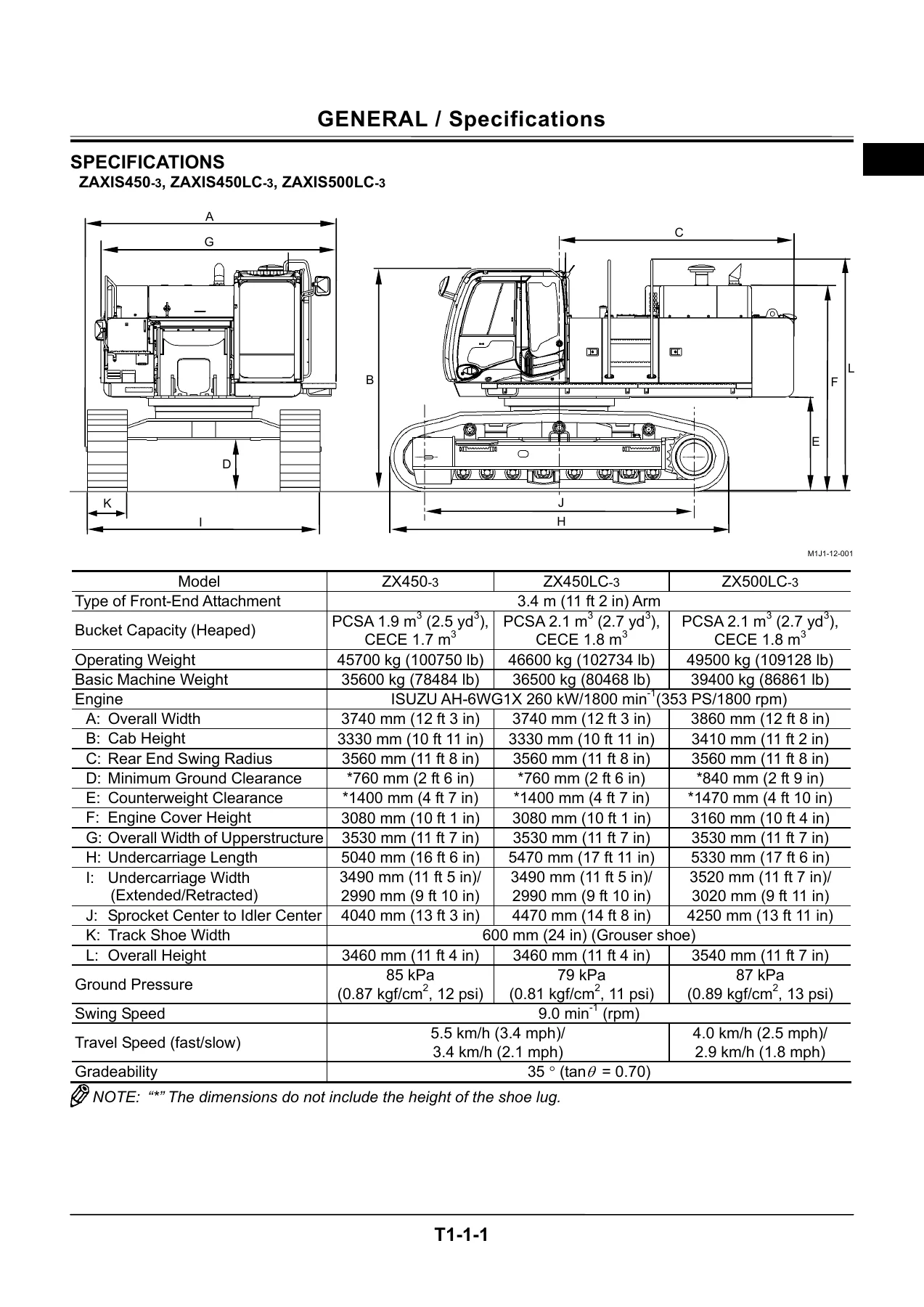
Group 1 Specificationsp. 9
Specificationsp. 9
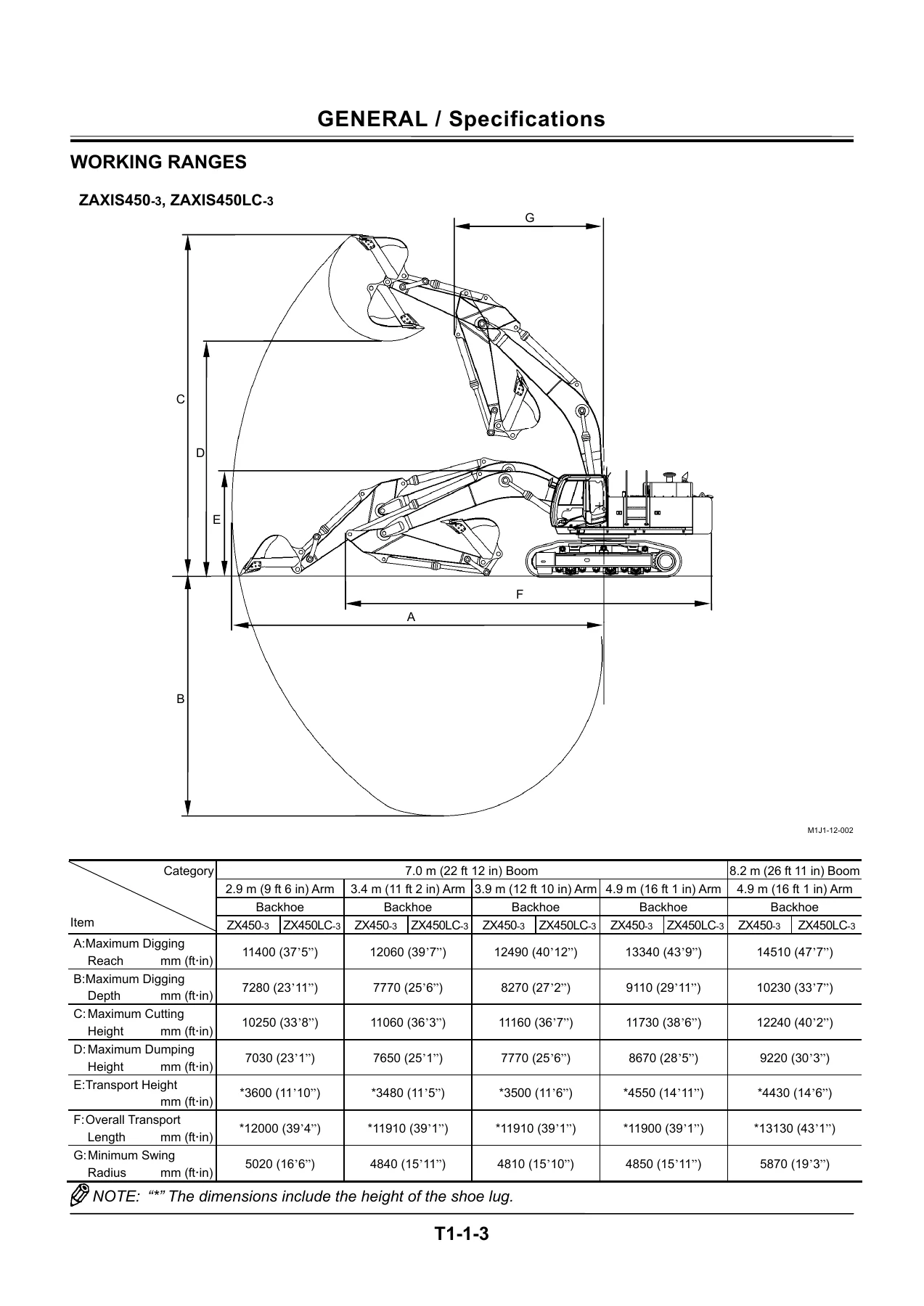
Working Rangesp. 11
Shoe Types and Applicationsp. 14
Bucket Types and Applications (Backhoe)p. 16
Group 2 Component Layoutp. 19
Main Component Layoutp. 19
Electrical Component Layoutp. 21
Enginep. 27
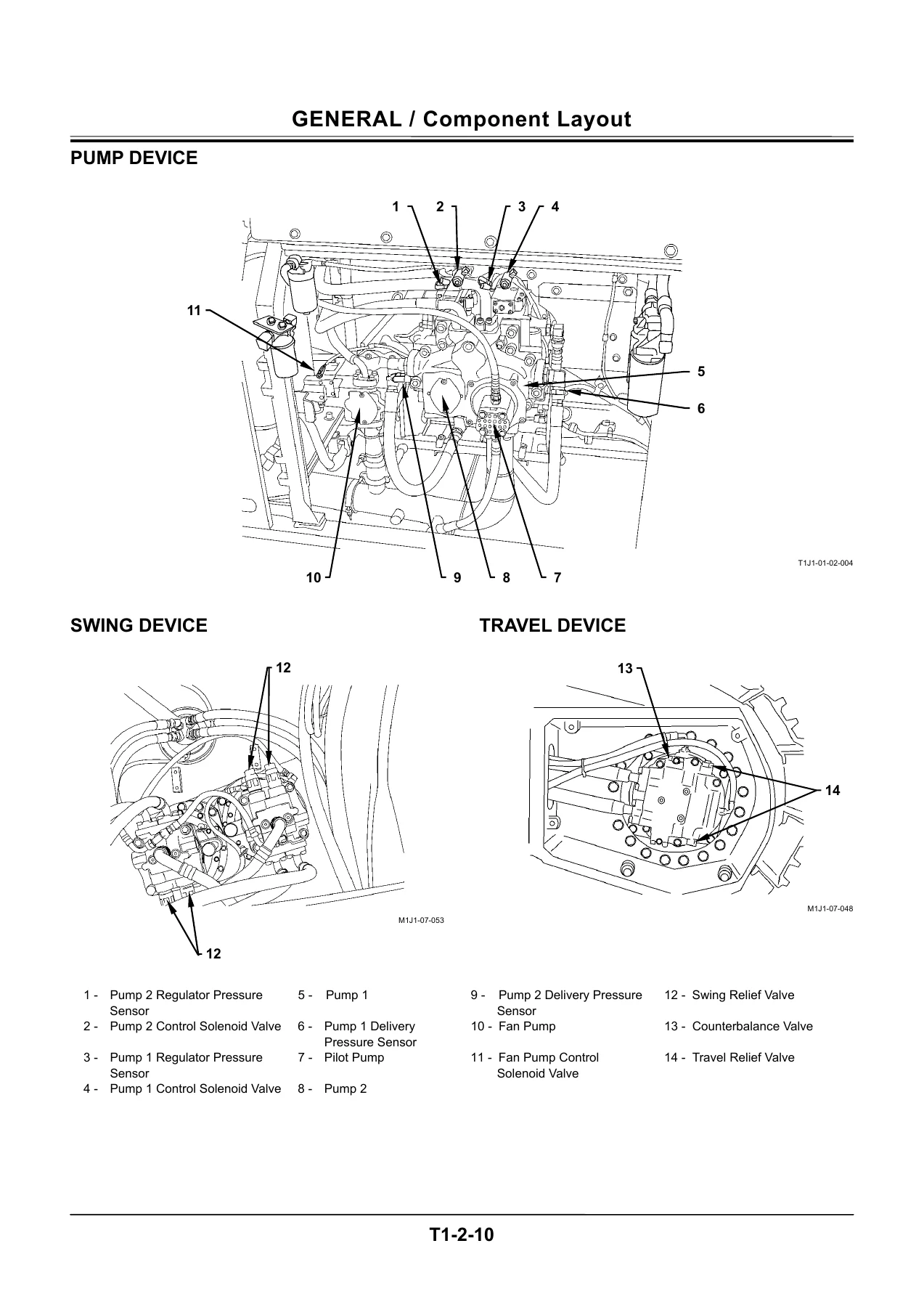
Pump Devicep. 28
Swing Devicep. 28
Travel Devicep. 28
Control Valvep. 29
Signal Control Valep. 40
Group 3 Component Specificationsp. 45
Enginep. 45
Engine Accessoriesp. 48
Hydraulic Componentp. 49
Electrical Componentp. 53
SECTION 2 SYSTEMp. 57
Group 1 Controllerp. 59
Outlinep. 59
Can: Controller Area Network (Network Provided for Machine)p. 60
MCF: Main Controllerp. 61
ECM: Engine Control Modulep. 70
ICF: Information Controllerp. 72
Monitor Unitp. 74
Group 2 Control Systemp. 83
Outlinep. 83
Engine Controlp. 86
Pump Controlp. 103
Valve Controlp. 124
Other Controlsp. 136
Group 3 ECM Systemp. 147
Outlinep. 147
Fuel Injection Controlp. 148
Engine Start Controlp. 156
EGR (Exhaust Gas Recirculation) Controlp. 158
Fuel Injection Amount Correctionp. 160
Fuel Filter Restriction Indicator Controlp. 161
Engine Stop Controlp. 162
Group 4 Hydraulic Systemp. 165
Outlinep. 165
Pilot Circuitp. 166
Main Circuitp. 178
Counterweight Removal / Installation Circuit (Optional)p. 188
Group 5 Electrical Systemp. 189
Outlinep. 189
Main Circuitp. 190
Electric Power Circuit (Key Switch: OFF)p. 192
Accessory Circuitp. 193
Starting Circuit (Key Switch: START)p. 194
Charging Circuit (Key Switch: ON)p. 196
Serge Voltage Prevention Circuitp. 200
Pilot Shut-Off Circuit (Key Switch: ON)p. 202
Security Lock Circuitp. 204
Engine Stop Circuit (Key Switch: OFF)p. 206
Security Horn Circuitp. 207
Working Light Circuitp. 208
Wiper / Washer Circuitp. 210
SECTION 3 COMPONENT OPERATIONp. 215
Group 1 Pump Devicep. 217
Outlinep. 217
Main Pump, Fan Pumpp. 218
Regulator for Main Pumpp. 220
Regulator for Fan Pumpp. 228
Pump 1, 2 Control Solenoid Valve Fan Pump Control Solenoid Valvep. 244
Pilot Pumpp. 246
Pump Delivery Pressure Sensorp. 246
Pump Regulator Pressure (Flow Rate Control Pressure) Sensorp. 246
Group 2 Swing Devicep. 247
Outlinep. 247
Swing Reduction Gearp. 248
Swing Motorp. 249
Swing Parking Brakep. 250
Valve Unitp. 252
Group 3 Control Valvep. 255
Outlinep. 255
Hydraulic Circuitp. 270
Main Relief Valvep. 274
Overload Relief Valve (with Make-Up Function)p. 276
Boom Overload Relief Control Valvep. 278
Flow Combiner Valvep. 280
Anti-Drift Valvep. 282
Regenerative Valvep. 286
Flow Rate Control Valvep. 290
Bypass Shut-Out Valvep. 294
Group 4 Pilot Valvep. 297
Outlinep. 297
Operationp. 300
Shockless Function (Only for Travel Pilot Valve)p. 310
Group 5 Travel Devicep. 311
Outlinep. 311
Travel Reduction Gearp. 312
Travel Motorp. 313
Travel Brake Valvep. 315
Parking Brakep. 322
Group 6 Signal Control Valvep. 325
Outlinep. 325
Pilot Portp. 326
Shuttle Valvep. 330
Shockless Valvep. 334
Arm Flow Rate Control Valve Control Spool, Flow Combiner Valve Control Spool, Swing Parking Brake Release Spoolp. 338
Group 7 Others (Upperstructure)p. 339
Pilot Shut-Off Solenoid Valvep. 339
4-Spool Solenoid Valve Unitp. 341
Pilot Relief Valvep. 343
Fan Motorp. 344
Fan Valvep. 345
Shockless Valvep. 346
Accumulatorp. 347
Distribution Valve (Optional)p. 348
Group 8 Others (Undercarriage)p. 351
Swing Bearingp. 351
Center Jointp. 352
Track Adjusterp. 353
TT1J1-E-00-SP(090421_5).pdf
COVERp. 358
INTRODUCTIONp. 360
SAFETYp. 362
SECTION AND GROUP CONTENTSp. 398
SECTION 4 OPERATIONAL PERFORMANCE TESTp. 400
Group 1 Introductionp. 402
Operational Performance Testsp. 402
Preparation for Performance Testsp. 403
Group 2 Standardp. 404
Operational Performance Standard Tablep. 404
Main Pump P-Q Diagramp. 408
Fan Pump P-Q Diagramp. 409
Fan Pump I-Q Diagramp. 410
Monitor Unit Indicating Values (MC)p. 411
Monitor Unit Indicating Values (ECM)p. 417
Sensor Activating Rangep. 418
Group 3 Engine Testp. 420
Engine Speedp. 420
Engine Compression Pressurep. 422
Valve Clearancep. 423
Lubricant Consumptionp. 426
Group 4 Excavator Testp. 428
Travel Speedp. 428
Track Revolution Speedp. 429
Mistrack Checkp. 430
Travel Motor Leakagep. 431
Swing Speedp. 432
Swing Function Drift Checkp. 433
Swing Motor Leakagep. 434
Maximum Swingable Slant Anglep. 435
Swing Bearing Playp. 437
Hydraulic Cylinder Cycle Timep. 439
Dig Function Drift Checkp. 441
Control Lever Operating Forcep. 442
Control Lever Strokep. 443
Boom Raise/Swing Combined Operation Checkp. 444
Group 5 Component Testp. 446
Primary Pilot Pressurep. 446
Secondary Pilot Pressurep. 448
Solenoid Valve Set Pressurep. 449
Main Pump Delivery Pressurep. 451
Fan Pump Delivery Pressurep. 452
Main Relief Valve Set Pressurep. 453
Overload Relief Valve Set Pressurep. 457
Main Pump Flow Rate Measurementp. 459
Fan Pump Flow Rate Measurementp. 461
Swing Motor Drainagep. 467
Travel Motor Drainagep. 469
SECTION 5 TROUBLESHOOTINGp. 474
Group 1 Diagnosing Procedurep. 476
Introductionp. 476
Diagnosing Procedurep. 477
Group 2 Monitor Unitp. 482
Outlinep. 482
How to Use Screensp. 491
Screen Display When An Alarm is Issuedp. 499
Contents of Alarmsp. 501
Troubleshootingp. 503
Controller Versionp. 505
Monitoringp. 507
Displaying Operating Conditionsp. 510
Pump 2 Flow Rate Adjustmentp. 511
Attachment Selectionp. 513
Time Setp. 516
Fuel Rate Display/No Displayp. 517
Back Monitor Settingsp. 521
Maintenance Settingsp. 528
Language Settingsp. 533
Group 5 Component Layoutp. 536
Main Component Layoutp. 536
Electrical Component Layoutp. 538
Enginep. 544
Pump Devicep. 545
Swing Devicep. 545
Travel Devicep. 545
Control Valvep. 546
Components in Control Valvep. 547
Pilot Portp. 557
Group 6 Troubleshooting Ap. 562
Troubleshooting A Procedurep. 562
MC Fault Code Listp. 563
ECM Fault Code Listp. 583
ICF Fault Code Listp. 595
Monitor Unit Fault Code Listp. 597
MC Fault Code 11000 to 11002p. 598
MC Fault Code 11003p. 599
MC Fault Code 11004p. 600
CAN Harness Checkp. 601
MC Fault Code 11101p. 621
MC Fault Code 11200p. 622
MC Fault Code 11202p. 623
MC Fault Code 11301p. 624
MC Fault Code 11302p. 625
MC Fault Code 11303p. 626
MC Fault Code 11400p. 627
MC Fault Code 11402p. 628
MC Fault Code 11404p. 629
MC Fault Code 11405p. 630
MC Fault Code 11410p. 631
MC Fault Code 11412p. 632
MC Fault Code 11802p. 633
MC Fault Code 11901p. 634
MC Fault Codes 11910, 11911, 11914, 11918, 11920, 11983, 11984p. 636
MC Fault Codes 11910, 11911, 11914, 11918, 11920, 11983, 11984 CAN Harness Checkp. 637
MC Fault Code 11989p. 640
MC Fault Code 11991p. 641
MC Fault Code 11992p. 642
MC Fault Code 11993p. 643
MC Fault Code 11994p. 644
MC Fault Code 11995p. 645
MC Fault Code 11997p. 646
MC Fault Code 11998p. 647
MC Fault Code 11999p. 648
ICF Fault Codes 14000 to 14003p. 650
ICF Fault Codes 14006, 14008p. 654
Monitor Unit Fault Code 13303p. 656
Monitor Unit Fault Code 13304p. 657
Monitor Unit Fault Codes 13306, 13308p. 658
Monitor Unit Fault Code 13310p. 659
Monitor Unit Fault Code 13311p. 660
Pilot Shut-Off Lever Alarmp. 661
Group 7 Troubleshooting Bp. 662
Troubleshooting B Procedurep. 662
Relationship between Machine Trouble Symptoms and Related Partsp. 663
Correlation between Trouble Symptoms and Part Failuresp. 681
Engine System Troubleshootingp. 697
All Actuator System Troubleshootingp. 715
Front Attachment System Troubleshootingp. 725
Swing System Troubleshootingp. 735
Travel System Troubleshootingp. 738
Other System Troubleshootingp. 743
Work After Replacing Componentsp. 769
Charge Air Conditioner with Refrigerantp. 770
Exchange Inspectionp. 779
Group 8 Electrical System Inspectionp. 784
Precautions for Inspection and Maintenancep. 784
Instructions for Disconnecting Connectorsp. 786
Fuse Inspectionp. 787
Fusible Link Inspection and Replacementp. 789
Battery Voltage Checkp. 789
How to Troubleshoot Alternator Malfunctionsp. 790
Continuity Checkp. 791
Voltage and Current Measurementp. 793
Check by False Signalp. 800
Test Harnessp. 801
SERVICE MANUAL REVISION REQUEST FORMp. 804
THE ATTACHED DIAGRAM LISTp. 805
TT1JK-E-00_circuit.pdf
ZX400R-3/ZX400LCH-3 HYDRAULIC CIRCUIT DIAGRAMp. 806
ZX400R-3/ZX400LCH-3 HYDRAULIC CIRCUIT DIAGRAM(BREAKER AND CRUSHER PIPING, 2-SPEED FLOW COMBINING PIPING)p. 807
ZX400R-3/ZX400LCH-3 HYDRAULIC CIRCUIT DIAGRAM(BOOM HOSE RUPTURE VALVE, ARM HOSE RUPTURE VALVE))p. 808
ZX400R-3/ZX400LCH-3 ELECTRICAL CIRCUIT DIAGRAMp. 809
ZX400R-3/ZX400LCH-3 ENGINE HARNESS 1p. 810
ZX400R-3/ZX400LCH-3 ENGINE HARNESS 2p. 811
ZX400R-3/ZX400LCH-3 CAB HARNESSp. 812
ZX400R-3/ZX400LCH-3 MONITOR UNIT HARNESSp. 813
ZX400R-3/ZX400LCH-3 CONNECTORSp. 814
W1J1-E-00(20150327).pdf
COVERp. 815
CONTENTSp. 855
SECTION 1 GENERALp. 857
Precautions for Disassembling and Assemblingp. 859
PRECAUTIONS FOR DISASSEMBLING AND ASSEMBLINGp. 859
Tighteningp. 867
TIGHTENING TORQUE SPECIFICATIONp. 867
TORQUE CHARTp. 869
PIPING JOINTp. 872
PERIODIC REPLACEMENT OF PARTSp. 876
Paintingp. 877
PAINTINGp. 877
Bleeding Air from Hydraulic Oil Tankp. 879
BLEED AIR FROM HYDRAULIC OIL TANKp. 879
SECTION 2 UPPERSTRUCTUREp. 883
Cabp. 885
REMOVE AND INSTALL CABp. 885
DIMENSIONS OF THE CAB GLASSp. 893
Counterweightp. 907
REMOVE AND INSTALL COUNTERWEIGHTp. 907
Main Framep. 909
REMOVE AND INSTALL MAIN FRAMEp. 909
Pump Devicep. 915
REMOVE AND INSTALL PUMP DEVICEp. 915
DISASSEMBLE PUMP DEVICEp. 928
ASSEMBLE PUMP DEVICEp. 938
MAINTENANCE STANDARDp. 951
ALLOWABLE LIMITS FOR CYLINDER BLOCKp. 952
DISASSEMBLE REGULATORp. 953
ASSEMBLE REGULATORp. 956
DISASSEMBLE FAN PUMPp. 960
ASSEMBLE FAN PUMPp. 967
MAINTENANCE STANDARDp. 973
DISASSEMBLE REGULATOR (FAN PUMP)p. 974
ASSEMBLE REGULATOR (FAN PUMP)p. 978
STRUCTURE OF PILOT PUMPp. 984
Control Valvep. 987
REMOVE AND INSTALL CONTROL VALVEp. 987
DISASSEMBLE CONTROL VALVE (4-SPOOL HOUSING SIDE)p. 990
ASSEMBLE CONTROL VALVE (4-SPOOL HOUSING SIDE)p. 996
DISASSEMBLE CONTROL VALVE (5-SPOOL HOUSING SIDE)p. 1002
ASSEMBLE CONTROL VALVE (5-SPOOL HOUSING SIDE)p. 1006
DISASSEMBLE CONTROL VALVE (4-SPOOL HOUSING UPPER AND LOWER SURFACES)p. 1012
ASSEMBLE CONTROL VALVE (4-SPOOL HOUSING UPPER AND LOWER SURFACES)p. 1018
DISASSEMBLE CONTROL VALVE (5-SPOOL HOUSING UPPER AND LOWER SURFACES)p. 1026
ASSEMBLE CONTROL VALVE (5-SPOOL HOUSING UPPER AND LOWER SURFACES)p. 1032
DISASSEMBLE CONTROL VALVE (4-SPOOL CONTROL VALVE)p. 1038
ASSEMBLE CONTROL VALVE (4-SPOOL CONTROL VALVE)p. 1042
DISASSEMBLE CONTROL VALVE (5-SPOOL CONTROL VALVE)p. 1044
ASSEMBLE CONTROL VALVE (5-SPOOL CONTROL VALVE)p. 1048
DISASSEMBLE CONTROL VALVE (HOUSING FRONT AND REAR SURFACES)p. 1050
ASSEMBLE CONTROL VALVE (HOUSING FRONT AND REAR SURFACES)p. 1052
DISASSEMBLE HOUSINGp. 1054
ASSEMBLE HOUSINGp. 1056
Swing Devicep. 1059
REMOVE AND INSTALL SWING DEVICEp. 1059
DISASSEMBLE SWING DEVICEp. 1062
ASSEMBLE SWING DEVICEp. 1072
DISASSEMBLE SWING MOTORp. 1082
ASSEMBLE SWING MOTORp. 1086
MAINTENANCE STANDARDp. 1090
Pilot Valvep. 1093
REMOVE AND INSTALL PILOT VALVEp. 1093
DISASSEMBLE RIGHT AND LEFT PILOT VALVESp. 1110
ASSEMBLE RIGHT AND LEFT PILOT VALVESp. 1114
DISASSEMBLE TRAVEL PILOT VALVEp. 1118
ASSEMBLE TRAVEL PILOT VALVEp. 1122
Pilot Shut-Off Solenoid Valvep. 1129
REMOVE AND INSTALL PILOT SHUT-OFF SOLENOID VALVEp. 1129
STRUCTURE OF PILOT SHUT-OFF SOLENOID VALVEp. 1131
Solenoid Valvep. 1133
REMOVE AND INSTALL SOLENOID VALVEp. 1133
STRUCTURE OF SOLENOID VALVEp. 1135
DISASSEMBLE AND ASSEMBLE PROPOTIONAL SOLENOID VALVEp. 1136
Signal Control Valvep. 1139
REMOVE AND INSTALL SIGNAL CONTROL VALVEp. 1139
STRUCTURE OF SIGNAL CONTROL VALVEp. 1141
Shockless Valvep. 1143
REMOVE AND INSTALL SHOCKLESS VALVEp. 1143
STRUCTURE OF SHOCKLESS VALVEp. 1145
Fan Valvep. 1147
REMOVE AND INSTALL FAN VALVEp. 1147
STRUCTURE OF FAN VALVEp. 1150
Fan Motorp. 1151
REMOVE AND INSTALL FAN MOTORp. 1151
STRUCTURE OF FAN MOTORp. 1175
Enginep. 1177
REMOVE AND INSTALL ENGINEp. 1177
SECTION 3 UNDERCARRIAGEp. 1205
Swing Bearingp. 1207
REMOVE AND INSTALL SWING BEARINGp. 1207
DISASSEMBLE SWING BEARINGp. 1210
ASSEMBLE SWING BEARINGp. 1212
Travel Devicep. 1215
REMOVE AND INSTALL TRAVEL DEVICEp. 1215
DISASSEMBLE TRAVEL DEVICEp. 1218
ASSEMBLE TRAVEL DEVICEp. 1232
DISASSEMBLE TRAVEL MOTORp. 1248
ASSEMBLE TRAVEL MOTORp. 1252
DISASSEMBLE BRAKE VALVEp. 1258
ASSEMBLE BRAKE VALVEp. 1260
MAINTENANCE STANDARDp. 1262
Center Jointp. 1265
REMOVE AND INSTALL CENTER JOINTp. 1265
DISASSEMBLE CENTER JOINTp. 1268
ASSEMBLE CENTER JOINTp. 1270
MAINTENANCE STANDARDp. 1275
Track Adjusterp. 1277
REMOVE AND INSTALL TRACK ADJUSTERp. 1277
DISASSEMBLE TRACK ADJUSTERp. 1278
ASSEMBLE TRACK ADJUSTERp. 1286
Front Idlerp. 1293
REMOVE AND INSTALL FRONT IDLERp. 1293
DISASSEMBLE FRONT IDLERp. 1296
ASSEMBLE FRONT IDLERp. 1302
MAINTENANCE STANDARDp. 1306
Upper and Lower Rollerp. 1309
REMOVE AND INSTALL UPPER ROLLERp. 1309
REMOVE AND INSTALL LOWER ROLLERp. 1312
DISASSEMBLE LOWER ROLLERp. 1316
ASSEMBLE LOWER ROLLERp. 1318
MAINTENANCE STANDARDp. 1320
Trackp. 1323
REMOVE AND INSTALL TRACKp. 1323
MAINTENANCE STANDARDp. 1335
SECTION 4 FRONT ATTACHMENTp. 1341
Front Attachmentp. 1343
HYDRAULIC CIRCUIT PRESSURE RELEASE PROCEDUREp. 1343
REMOVE AND INSTALL FRONT ATTACHMENTp. 1344
REMOVE AND INSTALL BUSHINGp. 1352
MAINTENANCE STANDARDp. 1354
STANDARD DIMENSIONS FOR ARM AND BUCKET CONNECTIONp. 1357
STANDARD DIMENSIONS FOR ARM AND BOOM CONNECTIONp. 1358
Cylinderp. 1359
REMOVE AND INSTALL CYLINDERp. 1359
DISASSEMBLE CYLINDERSp. 1372
ASSEMBLE CYLINDERSp. 1380
MAINTENANCE STANDARDp. 1386

Torque specifications are provided throughout the workshop manual, covering engine mounting bolts, hydraulic tank mounting, pump device mounting, control valve mounting, swing device mounting, swing bearing bolts, travel device mounting, track shoe bolts, track guard bolts, and counterweight mounting. The tightening torque specification tables give the bolt diameter, quantity, wrench size, and torque value in NΒ·m, kgfΒ·m, and lbfΒ·ft for each application. The torque chart covers socket bolts, hexagon M bolts, hexagon H bolts, and hexagon T bolts. The piping joint section covers union joints, O-ring seal joints, screw-in connections, and hose connections. The periodic replacement parts table lists the fuel hoses, pump suction and delivery hoses, swing hoses, travel hoses, boom cylinder line hoses, arm cylinder line hoses, bucket cylinder line hoses, and pilot hoses, with replacement intervals of every 2 years or 6000 hours.

The maintenance standards in the workshop manual give the standard dimensions and allowable limits for critical components. For the pump device, these include the clearance between the plunger outer diameter and cylinder block bore, the free length of the cylinder spring, the clearance between the plunger and shoe bottom, and the difference between the retainer surface and the spherical bushing top. For the swing motor, the clearance between the plunger outer diameter and rotor inner bore, the clearance between the plunger and shoe bottom, the shoe thickness, and the friction plate thickness. For the travel motor, the clearance between the cylinder block inner diameter and piston outer diameter, the clearance between the piston and shoe, the clearance at the case and piston mounting position, and the wear on the sliding surfaces of the cylinder block and valve plate. For the center joint, the bushing wear limit, sliding surface condition, and ring wear limits. For the track adjuster, the spring free length and assembly dimensions. For the front idler, the roller dimensions and axle/bushing wear limits. For the upper and lower rollers, the roller dimensions and axle/bushing wear limits. For the track, the link length, master pin dimensions, master bushing dimensions, grouser shoe height, bushing dimensions, and pin dimensions. For the front attachment, the pin and bushing dimensions at every connection point, plus side cutter and point wear limits.

The electrical system inspection section provides the precautions and procedures for working on the machine’s electrical system. It covers fuse inspection, fusible link inspection and replacement, battery voltage check, alternator malfunction troubleshooting, continuity checks for single-line and multi-line circuits, voltage and current measurement for the 24-volt circuit and the 5-voltage circuit, checking by false signal, and the test harness. The fuse box layout shows which fuse protects which circuit, from the light relay and wiper motor to the ECM main relay and pilot shut-off solenoid valve.

What This Manual Enables You to Do

The Hitachi ZX450-3 ZX470H-3 ZX500LC-3 ZX520LCH-3 Hydraulic Excavator Service Manual supports a wide range of professional work. You can diagnose machine faults using the fault code lists and symptom-based troubleshooting flowcharts. You can test engine speed, compression pressure, valve clearance, and lubricant consumption. You can measure travel speed, track revolution speed, mistrack, swing speed, swing drift, and cylinder cycle time. You can test primary and secondary pilot pressure, solenoid valve set pressure, main relief pressure, overload relief pressure, and pump flow rate. You can remove and install the pump device, control valve, swing device, travel device, pilot valve, signal control valve, fan valve, and fan motor. You can disassemble and assemble the main pump, fan pump, regulators, control valve spools, swing motor, travel motor, travel brake valve, pilot valves, and cylinders. You can replace bushings in the front attachment and adjust track tension. You can service the electrical system, including fuse and fuselage link inspection, battery and charging circuit checks, and continuity testing. You can reference tightening torques for every major fastener. You can check maintenance standards against allowable limits to decide whether a component needs repair or replacement.

Correct procedures and accurate specifications matter because these are heavy hydraulic machines operating under load. A pump installed with the wrong swash plate orientation, a control valve assembled with a damaged O-ring, a travel motor with excessive internal leakage, or a swing bearing with play beyond the allowable limit can lead to poor performance, premature failure, or unsafe operation. The relief valve set pressures, the pump flow rates, the engine speeds, and the cylinder cycle times all affect how the machine digs, swings, and travels. The torque values ensure that fasteners hold under vibration and load. The maintenance standards tell you when a component is worn beyond serviceability. Having this information in a single PDF means you can look up a specification, a procedure, or a diagnostic path without searching through multiple sources.

IMAGES PREVIEW

Hitachi ZX450-3 ZX470H-3 ZX500LC-3 ZX520LCH-3 Hydraulic Excavator Service Manual - Technical & Workshop Manual PDF β€” PDF page 9 preview
Hitachi ZX450-3 ZX470H-3 ZX500LC-3 ZX520LCH-3 Hydraulic Excavator Service Manual - Technical & Workshop Manual PDF β€” PDF page 11 preview
Hitachi ZX450-3 ZX470H-3 ZX500LC-3 ZX520LCH-3 Hydraulic Excavator Service Manual - Technical & Workshop Manual PDF β€” PDF page 28 preview

The manual is delivered as an instant PDF download. There is no shipping, no waiting, and no physical media to handle. You can access it on any device that reads PDF files, whether that is a laptop in the shop, a tablet in the field, or a desktop in the office. You can print the pages you need for a specific job, whether that is a single torque table, a hydraulic schematic, or a complete disassembly procedure. The PDF format keeps the original layout, illustrations, and tables intact, so the information appears exactly as it does in the source document.
Reviews

There are no reviews yet.

Be the first to review “Hitachi ZX450-3 ZX470H-3 ZX500LC-3 ZX520LCH-3 Hydraulic Excavator Service Manual – Technical & Workshop Manual PDF”

What Our Customers Say

β˜…β˜…β˜…β˜…β˜… Live reviews from customers
Loading customer reviews...
0
    0
    Your Cart
    Your cart is emptyReturn to Shop
    πŸ›’
    Recently Purchased
    πŸ•’ verified order