HondaJet HA-420 Pilot’s Operating Manual (POM) – Revision B2 (March 2017 Training Edition)
$39.95 Original price was: $39.95.$24.95Current price is: $24.95.
Master aircraft operations with the HondaJet HA-420 Pilot’s Operating Manual (POM) – Revision B2 (March 2017 Training Edition). Includes complete Garmin G3000 flight deck guides, HF120 turbofan engine systems, flight planning tables, and expanded operational procedures.
Description
Technical Document Overview & File Details
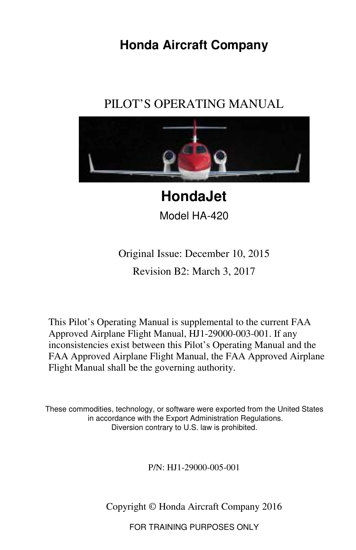
This authoritative HondaJet HA-420 Pilot’s Operating Manual (POM) – Revision B2 (March 2017 Training Edition) provides flight crews, type-rating candidates, and aviation technicians with extensive technical systems descriptions, detailed operating techniques, and comprehensive flight planning data. Published by Honda Aircraft Company under part number HJ1-29000-005-001, this manual serves as supplemental reference data to the FAA-approved Airplane Flight Manual (AFM HJ1-29000-003-001), detailing full system architecture and recommended standard operating procedures for the HondaJet HA-420.
- Manual Type: Pilot’s Operating Manual (POM) – Training Edition
- Brand & Manufacturer: Honda Aircraft Company, LLC (Greensboro, NC, USA)
- Aircraft Model: HondaJet Model HA-420
- Engines Covered: Twin GE Honda Aero Engines HF120 Turbofans (1,997 lbs thrust each)
- Document Part Number: HJ1-29000-005-001
- Publication Revision: Revision B2 (incorporating Revision B FIKI data and Revision B1 fuel icing inhibitor updates)
- Publication Date: March 3, 2017 (Original Issue: December 10, 2015)
- Page Count: 408 pages
- Language: English
- File Format: Adobe Acrobat PDF
Complete Chapters & Systems Coverage
The HondaJet HA-420 Pilot’s Operating Manual (POM) – Revision B2 (March 2017 Training Edition) is systematically organized into five detailed sections that thoroughly explain the operating envelope, cockpit switchology, and multi-system integration of this advanced light jet:
- Section 1 – Systems Description
- Fuselage, Empennage, Natural Laminar Flow Wing & Over-The-Wing Engine Mount (OTWEM) Pylon Structure
- Cabin Doors, Main Entry Door Airstair Mechanism, Emergency Exit Door & Baggage Access
- Cockpit Windows, Windshield Heating & Passenger Dimmable Shades
- Flight Deck, Displays, Control Panels, Center Pedestal & Circuit Breaker Panels
- Crew Seats, Passenger Club Seating, Lavatory & Emergency Safety Equipment
- GE Honda Aero Engines HF120 Powerplant, Dual FADEC Controls & Engine Start System
- Engine Fire Detection, Isolation Firewalls & Halon Fire Suppression
- Fuel Storage Tanks, Collector Cells, Motive Flow Ejector Pumps & Fuel Distribution
- Primary Flight Controls (Elevator, Aileron, Rudder) & Secondary Controls (Trim, Flaps, Speed Brakes)
- Hydraulic Power Module (DCMP), Reservoir & Isolated Accumulator Circuits
- Tricycle Trailing-Link Landing Gear, Steer-by-Wire Nosewheel Steering & Antiskid Brakes
- Pneumatic Bleed Air Supply, Pre-Coolers & Bleed Air Leak Detection (BALD)
- Dual-Zone Environmental Control System (ECS), Vapor Cycle Air Conditioning & Outflow Pressurization
- Crew and Passenger Oxygen System (CPOS), Quick-Don Masks & Auto-Deployment
- Ice and Rain Protection: Bleed Air Wing Anti-Ice, Engine Cowl Anti-Ice, EMEDS Horizontal Tail De-Ice & Heated Probes
- Split-Bus 28 VDC Electrical Power Generation, Starter-Generators, Lead-Acid Batteries & Solid State Relays
- Exterior LED Lighting Management & Interior Cabin/Cockpit Illumination Controls
- Garmin G3000 Integrated Avionics Architecture, Widescreen GDU 1400 Displays & Touchscreen CDUs
- Automatic Flight Control System (AFCS), Autopilot, Yaw Damper, Rudder Bias & Cruise Speed Control (CSC)
- Stall Warning and Protection System (SWPS) with Stick Shaker & Pusher
Complete PDF Bookmark TreeComplete Bookmarks
The complete bookmarks in the “HondaJet HA-420 Pilot's Operating Manual (POM) – Revision B2 (March 2017 Training Edition)” are as follows:
+POM SECTION 0 – FRONT MATTER-Rev B2 Alt Fuelsp. 1
LIST OF EFFECTIVE PAGESp. 3RECORD OF REVISIONSp. 5RECORD OF TEMPORARY REVISIONSp. 7LIST OF SERVICE BULLETINSp. 9DOCUMENTATION GROUPp. 11INTRODUCTIONp. 13SECTION CONTENTSp. 14REVISION INSTRUCTIONSp. 15+MANUAL CONVENTIONSp. 15
TABLE OF CONTENTSp. 15OPTIONAL EQUIPMENTp. 15USE OF L(R) AND L-Rp. 16USE OF L(R) VERSUS 1(2)p. 16NOTES, CAUTIONS, AND WARNINGSp. 16+POM SECTION 1 – SYSTEMS DESCRIPTION – REV B FIKIp. 17
+INTRODUCTIONp. 21
FUSELAGEp. 26EMPENNAGEp. 26WINGp. 27NACELLE AND PYLONp. 28+DOORSp. 28
Introductionp. 28Main Entry Doorp. 30Emergency Exit Doorp. 33Aft Baggage Doorp. 35Forward Baggage Doorp. 37External Power Access Doorp. 39Lavatory Service Doorp. 40Electrical Service Doorsp. 41Nacelle Access Doorsp. 42+Indicationsp. 44
CAS Messagesp. 46+WINDOWSp. 47
+Flight Compartmentp. 47
Cockpit Windshieldp. 47+Passenger Compartmentp. 47
Cabin Windowsp. 47Lavatory Skylight Windowsp. 47+FLIGHT DECK, CABIN AND COCKPITp. 49
GENERALp. 49+DISPLAYSp. 51
Primary Flight Displayp. 51Multi-Function Displayp. 52Control Display Unitp. 53Standby Instrumentp. 54+CONTROL PANELS AND CONTROLSp. 55
Controlsp. 55Gaspersp. 56Push-To-Talkp. 56Pressurization Panelp. 56Oxygen Panelp. 57Electrical Panelp. 58ELT Panelp. 59Landing Gear Panelp. 60Alternate Gear Releasep. 60Engine Start Panelp. 61Parking / Emergency Brakep. 61Thrust Lever Quadrantp. 62Ice Protection Panelp. 63Fuel Panelp. 65Trim Panelp. 66Windshield Heat Panelp. 67Pneumatic Panelp. 68Annunciator Panelp. 69Fire Panelp. 70AFCS Mode Control Panelp. 70AFCS Servo Power Panelp. 71+CEILINGp. 72
Overhead Consolep. 72Sun Visorp. 74+SIDE WALLSp. 74
+Side Ledgep. 74
Clipboardp. 76Cup Holderp. 76Oxygen Mask Containerp. 76Circuit Breaker Panelp. 76Storagep. 77+Audio Connection Panelp. 77
Fire Extinguisherp. 77Flashlightp. 78+FLIGHT CONTROLSp. 78
Yokep. 78Rudder Pedalsp. 80CREW SEATSp. 81+PASSENGER CABINp. 84
+Cabin Seatsp. 86
Tablesp. 86Lightingp. 86Cabinetsp. 87Lavatoryp. 87+Safety Equipmentp. 88
Ordinance Signs and Placardsp. 88Life Vests and Raftp. 88Oxygen Masksp. 89+BAGGAGE COMPARTMENTSp. 90
Forward Baggagep. 90Aft Baggagep. 90+ENGINE, FIRE PROTECTION AND FUELp. 91
+ENGINEp. 91
Introductionp. 91+Engine Control Systemp. 92
Engine Startp. 93Power settingp. 94Ground APU Modep. 95Takeoff Lockp. 95N1 Synchronizationp. 96Engine Limits Protectionp. 96Engine Ignition Systemp. 96Engine Oil Systemp. 97Engine Fuel Systemp. 98Engine Vibration Detection Systemp. 98Engine Drain Systemp. 98+Indicationsp. 99
CAS Messagesp. 100+FIRE PROTECTIONp. 103
Fire Isolationp. 103Engine Fire Detection Systemp. 103Engine Fire Suppression Systemp. 103+Indicationsp. 104
CAS Messagesp. 105+FUELp. 107
+Fuel Storage Systemp. 107
Wing Tanksp. 108Carry-Through Tankp. 108Fuselage Bladder Tankp. 108Drain Valve Arrangementp. 109+Fuel Distribution Systemp. 109
Electric Boost Pumpsp. 112Fuel Crossfeed Functionp. 112Engine Firewall Shutoff Valvep. 112Fuel Consumption Sequencep. 112+Fuel Venting Systemp. 113
Vent Float Valvesp. 113Vent Surge Tankp. 114Flame Arrestorp. 114Expansion Spacep. 114Aircraft Refueling Systemp. 115Fuel Gauging Systemp. 117+Indicationsp. 118
CAS Messagesp. 121+FLIGHT CONTROLSp. 123
+PRIMARY FLIGHT CONTROLSp. 124
Pitch Axisp. 124Roll Axisp. 124Yaw Axisp. 124Gust Locksp. 124+SECONDARY FLIGHT CONTROLSp. 126
Pitch Trim Systemp. 126Roll Trim Systemp. 126Yaw Trim Systemp. 126Flapsp. 127Speed Brakep. 128+Indicationsp. 129
CAS Messagesp. 130+HYDRAULICS AND LANDING GEARp. 133
+HYDRAULIC SYSTEMp. 133
+Indicationsp. 136
CAS Messagesp. 138+LANDING GEARp. 139
Main Landing Gearp. 139Nose Landing Gearp. 140Alternate Gear Extensionp. 141+Indicationsp. 141
CAS Messagesp. 142+WHEELS AND BRAKESp. 143
Main Landing Gear Wheel and Tire Assemblyp. 143Nose Landing Gear Wheel and Tire Assemblyp. 143Normal Brakesp. 143Emergency/Parking Brakep. 144Indicationsp. 145+NOSEWHEEL STEERINGp. 145
CAS Messagesp. 146+PNEUMATICS AND ENVIRONMENTALp. 147
+BLEED AIR SUPPLY SYSTEMp. 147
Indicationsp. 149+ENVIRONMENTAL CONTROL SYSTEMp. 149
+Air Conditioningp. 152
Temperature Controlp. 153+Cabin Air Distributionp. 155
Cockpit Climate Zonep. 157Cabin Climate Zonep. 157+Indicationsp. 157
CAS Messagesp. 159+PRESSURIZATIONp. 160
Primary Outflow Valvep. 160Secondary Outflow Valvep. 160Limitersp. 160Cabin Pressurization Data Unitp. 161Normal Operationp. 161High Field Operationp. 162Cabin Dumpp. 163Cabin Altitude Hold Modep. 163+Indicationsp. 163
CAS Messagesp. 165+BLEED AIR LEAK DETECTIONp. 166
+Indicationsp. 168
CAS Messagesp. 168+OXYGENp. 169
+Crew Oxygenp. 169
Normal Modep. 171100% Oxygen Modep. 171Emergency Modep. 171Crew Mask Storagep. 171Audiop. 172Passenger Oxygenp. 172+Indicationsp. 172
CAS Messagesp. 173+ICE AND RAIN PROTECTIONp. 175
Wing Ice Protection Systemp. 176Engine Inlet Ice Protection Systemp. 178Horizontal Tail Ice Protection Systemp. 178When activated, the EMEDS begins to fire in a 2-minute cycle with 20 seconds of “active firing” and a 100-second period of “dwell” between firings. If operating in the NORM mode, once the ice detected signal is removed, the HTIPS will complete the pre…p. 179Windshield Ice and Rain Protection Systemp. 179Ice Detection Systemp. 179Ice Inspection Lightsp. 180+Indicationsp. 180
Wing Ice Protection Systemp. 180Engine Inlet Ice Protection Systemp. 180Horizontal Tail Ice Protection Systemp. 181Windshield Vision Protection Systemp. 181Air Data Probes Heat Systemp. 181Ice Detection Systemp. 181Ice Inspection Lightsp. 181CAS Messagesp. 183ELECTRICALp. 187+POWER GENERATION AND STORAGEp. 189
Starter-Generatorsp. 189Batteriesp. 189External Powerp. 190+LOAD DISTRIBUTIONp. 190
Cabin Powerp. 191+Indicationsp. 191
CAS Messagesp. 194+LIGHTINGp. 197
+EXTERIOR LIGHTINGp. 197
Landing Lightsp. 200Recognition Lightsp. 200Taxi Lightsp. 200Strobe / Navigation Lightsp. 200Ice Inspection Lightsp. 200Beacon Lightp. 200Logo Lightsp. 200+Indicationsp. 201
CAS Messagesp. 201+INTERIOR LIGHTINGp. 202
Cockpit Lighting Systemp. 202Cabin Lighting Systemp. 205+AVIONICS AND AFCSp. 207
+AVIONICSp. 207
Initializationp. 210Aircraft System Datap. 210Reversionary Modep. 212+Crew Alerting Systemp. 213
CAS Messagesp. 213CAS Acknowledgementp. 214Phase Inhibitsp. 214Takeoff Configuration Warningp. 214CDU Messagesp. 214Primary Air Data and Temperaturep. 215Primary Attitude and Heading Datap. 215Standby Instrumentp. 216System Synoptic Pagesp. 217System Control Pagesp. 219System Tests Pagesp. 223+Communication Systemsp. 225
VHF Communicationp. 225Intercomp. 225Cockpit Speakersp. 225Controller Pilot Data Link Communicationp. 226SatCom (Iridium) Telephone (Optional)p. 227+Navigation Systemsp. 227
VOR, ILS/Marker Beaconp. 227GPS-based Navigationp. 227Automatic Direction Finderp. 228Distance Measuring Equipmentp. 228Radio Altimeterp. 229+Surveillance Systemsp. 229
Diversity Capable Mode S Transponderp. 229Traffic Collision Avoidance System I (TCAS I)p. 230Traffic Collision Avoidance System IIp. 230Emergency Locator Transmitterp. 230Cockpit Voice and Flight Data Recorderp. 231+Weather and Terrain Awareness Systemsp. 231
Weather Radarp. 231SiriusXM® Weather Data Linkp. 232ConnextTM Weather Data Linkp. 232Terrain Awareness and Warning System Bp. 232Windshearp. 233Synthetic Visionp. 233+Electronic Flight Bag Functionsp. 233
FliteChartsp. 233Jeppesen Chartviewp. 233Electronic Checklistsp. 233SafeTaxip. 234SurfaceWatch™p. 234Document Viewerp. 234+Maintenance and Diagnosticsp. 234
CAS Messagesp. 235+AUTOMATIC FLIGHT CONTROLp. 238
+Flight Directorp. 239
Navigationp. 239Headingp. 239Altitudep. 240Vertical Navigationp. 240Vertical Speedp. 240Flight Level Changep. 240Approachp. 241Takeoff and Go-aroundp. 241Autopilotp. 241Yaw Damper and Turn Coordinationp. 242Rudder Biasp. 242Cruise Speed Controlp. 243Stall Warning and Protectionp. 245+Trim Controlp. 246
CAS Messagesp. 246+POM SECTION 2 – FLIGHT PLANNING Rev Bp. 249
INTRODUCTIONp. 251+POM SECTION 3 – OPERATING PROCEDURES AND TECHNIQUES – REV B FIKIp. 287
+GENERALp. 291
RESPONSIBILITIESp. 291COCKPIT/CREW RESOURCE MANAGEMENTp. 292CHECKLISTp. 292CREW ALERTINGp. 294+PREFLIGHT INSPECTIONp. 297
PRELIMINARY EXTERIOR INSPECTIONp. 297COCKPIT/CABIN INSPECTIONp. 297EXTERIOR INSPECTIONp. 298+GROUND OPERATIONSp. 298
+BEFORE STARTING ENGINESp. 298
Oxygenp. 298Trim Panelp. 299Standby Instrumentp. 299Exterior Lightsp. 299Avionics Initializationp. 300+STARTING ENGINESp. 301
Passenger Briefingp. 301Rudder Pedalsp. 301Seats, Safety Beltsp. 301Doorsp. 301CAS Messagesp. 302Single Engine Cooling / Heatingp. 302Engine Anti-Icep. 302External Powerp. 302+BEFORE TAXIp. 303
Wing Anti-Icep. 303+Avionics / Flight Datap. 303
Runwayp. 304Flapsp. 304Parking Brakep. 304TAXIp. 304+BEFORE TAKEOFFp. 305
CAS Messagesp. 305Navigationp. 305Flight Guidancep. 305TOLD Datap. 305Takeoff Briefingp. 306Radarp. 307Ice Protectionp. 307+TAKEOFFp. 307
ROLLING TAKEOFFp. 308PERFORMANCE TAKEOFFp. 308+AFTER TAKEOFFp. 309
Ice Protectionp. 309+ENROUTE OPERATIONSp. 311
CLIMBp. 311CRUISEp. 311DESCENTp. 311+TERMINAL AREA OPERATIONSp. 311
+APPROACHp. 311
Passenger Briefingp. 311Avionicsp. 312Landing Datap. 312CAS Messagesp. 313Approach Briefingp. 313+INSTRUMENT APPROACHp. 314
Initial Approach – Procedure Turn/Course Reversalp. 314Initial Approach – No Procedure Turnp. 314Vectors to Finalp. 315+Final Approachp. 315
Approach with Vertical Guidancep. 316Non-precision Approach (without vertical guidance)p. 316Circlingp. 316Instrument Approach Profilesp. 319VFR PATTERNp. 321+LANDINGp. 322
NORMAL LANDINGp. 322CROSSWIND LANDINGp. 322+BALKED LANDINGp. 323
MISSED APPROACHp. 324AFTER LANDINGp. 325+SHUTDOWNp. 326
EXTERNAL POWERp. 326THRUST LEVERSp. 326SECURING THE AIRCRAFTp. 326+EMERGENCY AND ABNORMAL PROCEDURESp. 327
ENGINE FAILURE DURING Takeoffp. 327+SINGLE-ENGINE APPROACH AND LANDINGp. 331
Approach Briefing (Before Landing)p. 331TAWS Warningp. 331SINGLE ENGINE INSTRUMENT APPROACH PROFILESp. 333Approaches in Icingp. 335+REDUCED FLAp landingp. 337
Approach Briefingp. 338TAWS Warningp. 339EMERGENCY DESCENTp. 339+ADDITIONAL MANEUVERSp. 340
STEEP TURNSp. 340STALLSp. 342+POM SECTION 4 – SERVICE, HANDLING, AND MAINTENANCE – REV B FIKIp. 349
GENERALp. 351+TOWINGp. 351
TOWING PROCEDUREp. 351+MOORINGp. 355
COVERSp. 356GUST LOCKp. 357EMERGENCY EXIT DOOR LOCKp. 358+FUEL SERVICINGp. 359
FUELING: OPTIONAL EXTERNAL FUEL GAUGE INSTALLEDp. 361FUELING: OPTIONAL EXTERNAL FUEL GAUGE NOT INSTALLEDp. 363+OIL SERVICINGp. 365
SERVICING THE ENGINE OIL SYSTEMp. 367OIL LEVEL CHECKp. 368OXYGEN SERVICINGp. 369TIRESp. 371+WASTE WATER SERVICINGp. 373
INTERNAL SERVICINGp. 373EXTERNAL SERVICINGp. 375NON-POTABLE/GREY WATER SERVICINGp. 379SCREEN CLEANINGp. 381WINDSHIELD CLEANINGp. 381+GROUND DE-ICINGp. 382
GENERALp. 382DE-ICING/ANTI-ICING FLUIDSp. 382+DE-ICING METHODSp. 383
Using Mechanical Means to De-icep. 383+Using Fluids to De-ice/Anti-icep. 383
Horizontal Tailp. 387Vertical Stabilizer/Rudderp. 387Fuselagep. 388Wingp. 388Enginesp. 389Landing Gearp. 389Doorsp. 389PREFLIGHT DE-ICING INSPECTION CHECKLISTp. 390+POM SECTION 5 – GLOSSARY – REV B FIKIp. 393
Over-Speed Protection Systemp. 403Pre-Coolerp. 403Pressure Demandp. 403Power Distribution Unitp. 403Pilot Flyingp. 403Primary Flight Displayp. 403Primary Flight Windowp. 403Pilot In Commandp. 403Permanent Magnet Alternatorp. 403Pilot Not Flyingp. 404Primary Outflow Valvep. 404Pilot Operating Manualp. 404Positionp. 404Altitude measured from standard sea level pressure (29.92 in hg) by a pressure altimeter. It is the indicated pressure altitude corrected for position and instrument error. In this manual, altimeter instrument errors are assumed to be zero. Position errors may be obtained from the correction tables/charts.p. 404Static air temperature. The ambient free air static temperature obtained from either: 1) ground meteorological sources, orp. 405Service Bulletinp. 405Steering Control Unitp. 405Steering Control Valve And Actuator Assemblyp. 405Secure Digitalp. 405Second In Commandp. 405Standard Instrument Departurep. 405Sea Levelp. 405Shutoff Valvep. 405Secondary Outflow Valvep. 405Speed Selectp. 406Solid-State Relaysp. 406Standard Terminal Arrival Routep. 406Standbyp. 406Synthetic Visionp. 406Synthetic Vision Technologyp. 406Stall Warning/Protection Systemp. 406True Air Speedp. 406Total Air Temperaturesp. 406Terrain Awareness Warning Systemp. 406To Be Determinedp. 406Traffic Alert And Collision Avoidance Systemp. 406Temporary Flight Restrictionsp. 406Track Angle Errorp. 406Thrust Lever Anglep. 406Temperature Modulating Valvesp. 406Takeoffp. 406Top Of Descentp. 407Takeoff Go Aroundp. 407Trackp. 407Takeoff Decision Speedp. 407Takeoff Safety Speedp. 407Approach Climb Speedp. 407Volts Direct Currentp. 407Vibration Detection Systemp. 407Visual Flight Rulesp. 407Very High Frequencyp. 407Maximum Operating Airspeed (270 Kcas). The Speed That May Not Be Deliberately Exceeded In Any Flight Condition.p. 407Visual Meteorological Conditionsp. 407Vertical Navigationp. 407Vertical Navigationp. 407Very High-Frequency Omni-Directional Rangep. 407Rotation Speedp. 407Landing Reference Speedp. 408Vertical Speed Modep. 408Vertical Situation Displayp. 408Vertical Speed Requiredp. 408Wing Anti-Ice Air Valvep. 408Wing Anti-Ice Cross Flow Valvep. 408Windshield Heat Controllersp. 408Wing Ice Protection Systemp. 408 - Section 2 – Flight Planning
- Performance Data Introduction & Ambient Condition Adjustments
- Two-Engine Climb Performance Schedules
- Long Range Cruise Performance Tables
- High Speed Cruise Performance Profiles
- Descent Performance Data
- Holding Fuel Flow & Speed Schedules
- All-Engine & One-Engine Inoperative Altitude Capabilities
- Section 3 – Operating Procedures and Techniques
- Crew Resource Management, Single-Pilot Workload & Checklist Conventions
- Crew Alerting System (CAS) Classification & Aural Alert Management
- Expanded Cockpit, Cabin & Exterior Walkaround Inspection
- Engine Start Procedures (Ground, Cross-Start, Windmilling, Starter-Assisted)
- Taxi Operations, Brake Checks & Nosewheel Steering Verification
- Takeoff Techniques: Rolling Takeoff, Performance Static Takeoff & Crosswind Operations
- Climb, Enroute Cruise Monitoring & High-Altitude Descent Profile Management
- Terminal Area Operations, Instrument Approaches (ILS, VOR, GPS/RNAV) & Visual Traffic Patterns
- Normal, Crosswind, Balked Landing & Missed Approach Execution
- Engine Shutdown, Parking Brake Management & Aircraft Post-Flight Security
- Abnormal & Emergency Procedures: Engine Failure on Takeoff, Single-Engine Approaches & Emergency Descent
- Airwork Maneuvers: Steep Turns, Clean/Configured Stall Entry & Recovery Profiles
- Section 4 – Service, Handling, and Maintenance
- Ground Handling, Towing Limits (60° with torque links, 360° disconnected) & Mooring Points
- Aircraft Tie-Downs, Protective Covers & Rudder/Control Surface Gust Locks
- Single-Port Gravity Refueling Procedures, Approved Fuel Grades & Icing Inhibitors
- Engine Oil Servicing (6.1 Quart Capacity) & Sight Glass Inspection
- Hydraulic Reservoir Servicing (1.27 Gallon System Capacity)
- Oxygen Cylinder Servicing (50 cu ft, 1,850 psig) & Burst Disk Criteria
- Tire Inflation Pressures, Fusible Plugs & Brake Wear Indicator Inspection
- Section 5 – Glossary
- Aviation Acronyms, Operational Terminology & Systems Logic Abbreviations
Together, these chapters provide pilots and operations personnel with complete, end-to-end technical documentation. Rather than simply summarizing flight handbook steps, this volume explains the electro-mechanical logic, sensor inputs, automated protections, and normal cockpit workflows necessary to command the aircraft safely and efficiently in high-altitude turbine operating environments.
Airframe, Powerplant & Flight Control Systems
The HondaJet HA-420 features an advanced carbon-fiber composite fuselage engineered with co-cured and honeycomb sandwich structures to minimize aerodynamic drag and optimize natural laminar flow. The all-metal wing utilizes milled aluminum skins with integrated structural spars and ribs. Outstanding high-speed characteristics are achieved through 14 underside vortex generators, winglet fences, vortilons, and upper-wing high-Mach airflow bumps.
Thrust is provided by two pylon-mounted GE Honda Aero Engines HF120 turbofans producing 1,997 lbs of thrust each at sea level (flat rated to 77°F / 25°C). Configured in Honda’s patented Over-The-Wing Engine Mount (OTWEM) geometry, the engines reduce cabin noise and fuselage structural weight while eliminating engine support carry-through structures inside the aft fuselage. Thrust control is mediated via dual-channel Full Authority Digital Engine Control (FADEC) units, permanent magnet alternators (PMA), and throttle quadrant rotary variable differential transformers (RVDT). The system incorporates automated start abort logic, N1 synchronization, rotor overspeed protection (OSP), and an innovative Ground APU mode that automatically elevates idle speed on a single engine to drive the generator.
Flight control surfaces utilize a fully reversible mechanical design incorporating push-pull tubes, cables, bellcranks, and sectors for the ailerons, split elevators, and mass-balanced rudder. Pitch, roll, and yaw axes feature electrically actuated trim tabs with full cockpit feedback. High-lift capability is managed by electrically driven, 30%-chord double-slotted Fowler flaps commanded via three distinct detents (UP, TO/APPR, LDG) and monitored by an electronic Flap Actuation Controller (FAC). A hydraulically operated tailcone dual-panel speed brake provides constant drag across varying speeds via blow-back aerodynamic dampening.
Garmin G3000 Integrated Avionics & AFCS Automation
At the core of the flight deck is the Garmin G3000 integrated avionics suite, presenting navigation, tactical flight data, and aircraft systems monitoring across three 14-inch widescreen GDU 1400 displays. Crew input and system configuration are managed through dual pedestal-mounted touchscreen Control Display Units (CDUs) equipped with raised bezels and grip visors for hand stabilization in turbulence. The avionics suite incorporates:
IMAGES PREVIEW
- Dual Integrated Avionics Computers (IAC) managing dual WAAS GPS receivers, VHF Com radios, and VHF Nav (VOR/ILS/Marker Beacon).
- Dual GRS 77 Attitude and Heading Reference Systems (AHRS) paired with GMU 44 magnetometers.
- Integrated full-time Engine Information System (EIS) and Aircraft System Information (ASI) readouts.
- Six full-color system synoptic pages: Status, Environmental, Electrical, Fuel, Hydraulics, and Ice Protection.
- Digital Automatic Flight Control System (AFCS) featuring a two-axis digital autopilot, yaw damper, automatic rudder bias to compensate for asymmetric thrust during single-engine flight, and Cruise Speed Control (CSC) which modulates engine N1 within a 5% authority window.
- Comprehensive Stall Warning and Protection System (SWPS) driving an active stick shaker, stick pusher, and Low Speed Awareness (LSA) cues on the PFD airspeed tape.
- Garmin GWX-70 digital color weather radar with 120-degree horizontal sweep, vertical profiling, and pitch-and-roll antenna stabilization.
Fuel, Hydraulic, Environmental & De-Ice Engineering
The manual provides complete operational schematics for all primary utility systems:
- Fuel Storage & Feed: 430.7 US gallons (2,890 lbs Jet A) distributed across four interconnected tanks: Left Wing (93.5 gal), Right Wing (93.5 gal), and Center Section (243.7 gal comprising the under-fuselage carry-through and aft bladder tank). Motive-flow ejector pumps continually supply 14.7-gallon collector tanks containing electric boost pumps for starting, crossfeed, and low-pressure backup.
- Hydraulic Power: Electric DC motor pump (DCMP) maintaining system operating pressure between 2,500 and 2,950 psig (1,725–1,875 psig on battery power on the ground). Isolated accumulators supply the landing gear, normal/antiskid multi-disc steel brakes, steer-by-wire nosewheel steering, and emergency/parking brake.
- Environmental & Pressurization: Regulated bleed air from engine high-pressure compressors conditioned through pre-coolers, heat exchanger packs, and dual Temperature Modulating Valves (TMV). Two independent cabin climate zones are cooled by a Vapor Cycle System (VCS). Pressurization is regulated via primary and secondary outflow valves to deliver scheduled cabin altitudes with mechanical altitude limiters active at 13,500 ± 500 feet.
- Ice & Rain Protection: Engine bleed air anti-icing for wing leading edges via piccolo tubes and engine cowls; electro-mechanical expulsive de-icing system (EMEDS) utilizing 20 internal coil actuators to shatter ice accretion along the horizontal stabilizer; electrically heated gold-film windshields; and electrically heated air data probes.
Training Publication Notice
Please note: This manual is clearly designated by Honda Aircraft Company FOR TRAINING PURPOSES ONLY. It is designed to develop comprehensive operational understanding and systems mastery during initial, recurrent, or transition flight training. It acts as a supplemental document to the FAA-approved Airplane Flight Manual (AFM HJ1-29000-003-001) and must not be used as a substitute for the official AFM or governing operating authority during line flight operations.
Professional Flight Crew Reference & Instant Download
Acquiring this HondaJet HA-420 Pilot’s Operating Manual (POM) – Revision B2 (March 2017 Training Edition) gives corporate flight departments, simulator instructors, professional contract aviators, and maintenance technicians an indispensable technical asset. Having the full operational logic, cockpit controls layout, performance planning charts, and systems synoptic schematics at your fingertips ensures accurate operational decision-making and rigorous training preparation. This manual is delivered immediately upon checkout as an instant PDF download with no waiting and no shipping costs. The digital file is fully printable and optimized for easy viewing across Apple iPad, Android tablets, laptops, and desktop computers.
What Our Customers Say
🌟 Related Products
Discover more professional manuals for your equipment

Mooney M20M Series Aircraft Illustrated Parts Catalog (S/N 27-0001 Thru 27-TBA)

Piper PA-31T PA-31T1 PA-31T2 Cheyenne Parts Catalog - Card 1 of 5 (P/N 753 825)

Beech 1900 Airliner Maintenance Training Manual Volume 1 - 2nd Edition PDF


Reviews
There are no reviews yet.