
Hyundai HX225S L Hydraulic Excavator Service Manual – Full Workshop PDF
Original price was: $44.95.$26.95Current price is: $26.95.
Complete Hyundai HX225S L Hydraulic Excavator Service Manual in PDF, covering the standard, Long Reach and High Walker machines across hydraulics, electrical, mechatronics, troubleshooting, maintenance standards and full disassembly/assembly. 586-page workshop reference, instant download.
Description
Hyundai HX225S L Hydraulic Excavator Service Manual – Full Workshop PDF
This Hyundai HX225S L Hydraulic Excavator Service Manual is a complete workshop-grade reference for the HX225S L crawler excavator, covering the standard machine together with the Long Reach and High Walker variants in one PDF. It is the same style of service information used in a Hyundai service workshop: understand the structure and function of a component, follow the hydraulic or electrical circuit that drives it, isolate the fault with a troubleshooting chart, judge wear against a published service limit, then disassemble and rebuild with the correct tightening torques and assembly notes. Whether the job is a slow boom circuit, a swing drift that will not settle, a curved travel, a mechatronics fault code on the cluster, or a weeping cylinder, this Hyundai HX225S L service manual gives you the real procedure instead of a generic guess.
Because the manual is written for the HX225S L specifically, every torque value, service limit, port name, connector number, error code and circuit path in it belongs to this machine. That matters when a fault is intermittent, when a component is being reconditioned, or when an assembly has to go back together exactly as it came apart.
File Details
- Manual type: Service Manual (Workshop / Repair Manual)
- Brand: Hyundai
- Model: HX225S L, HX225S L Long Reach, HX225S L High Walker
- Engine: Cummins B5.9
- Language: English
- File format: PDF
- Page count: Approximately 586 pages
- Section layout: 1 General, 2 Structure and Function, 3 Hydraulic System, 4 Electrical System, 5 Mechatronics System, 6 Troubleshooting, 7 Maintenance Standard, 8 Disassembly and Assembly
Chapters Covered
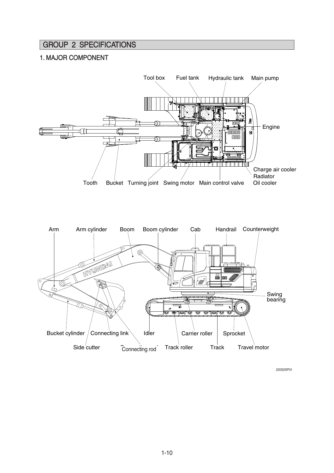
- Section 1 General – Safety procedures, protective equipment, emergency preparation, machine specifications and major component specifications
- Section 2 Structure and Function – Pump Device, Main Control Valve, Swing Device, Travel Device, RCV Lever, RCV Pedal
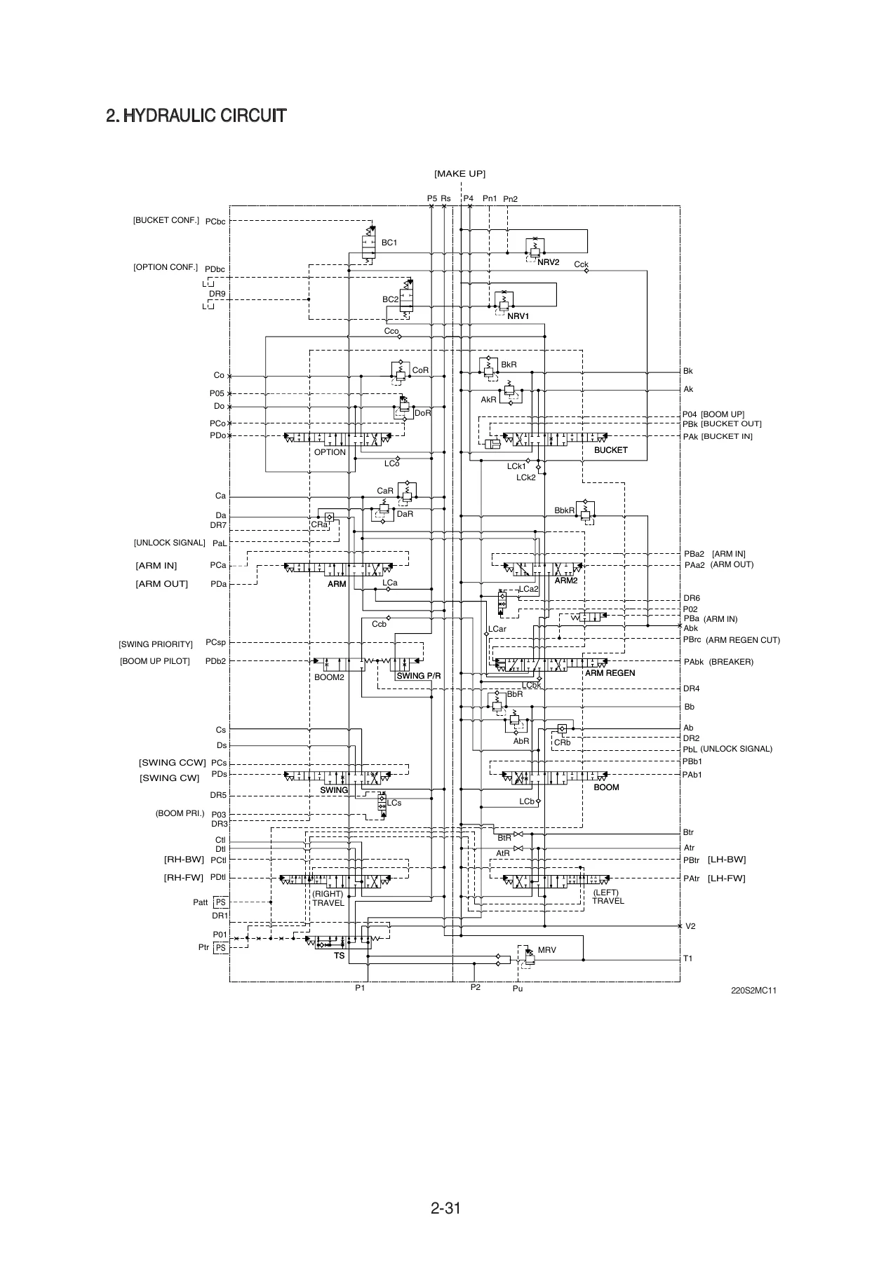
- Section 3 Hydraulic System – Hydraulic Circuit, Main Circuit, Pilot Circuit, Single Operation, Combined Operation
- Section 4 Electrical System – Component Location, Electrical Circuit, Electrical Component Specification, Connectors
- Section 5 Mechatronics System – Outline, Mode Selection, Automatic Deceleration, Power Boost, Travel Speed Control, Automatic Warming Up, Engine Overheat Prevention, Variable Power Control, Attachment Flow Control, Intelligent Power Control, Anti-Restart, Self-Diagnostic, Engine Control, EPPR Valve, Monitoring, Fuel Warmer
- Section 6 Troubleshooting – Before Troubleshooting, Hydraulic and Mechanical System, Electrical System, Mechatronics System
- Section 7 Maintenance Standard – Operational Performance Test, Major Components, Track and Work Equipment
- Section 8 Disassembly and Assembly – Precaution, Tightening Torque, Pump Device, Main Control Valve, Swing Device, Travel Device, RCV Lever, Turning Joint, Boom / Arm / Bucket Cylinder, Undercarriage, Work Equipment
Taken as a whole, those eight sections cover the entire machine – the tandem axial piston pump and its regulator, the ten-spool two-block main control valve with its holding, relief, negative control and swing priority functions, the swing motor and two-stage planetary reduction gear, the travel motor with counterbalance and parking brake, the remote control valves and pedal, the turning joint, the boom, arm and bucket cylinders, the undercarriage and the full mechatronics layer that ties engine and pump together. The Hyundai HX225S L Hydraulic Excavator Service Manual is structured so it can be used both as a study reference and as a bench-side guide during an active repair.
Hydraulics and Machine Systems
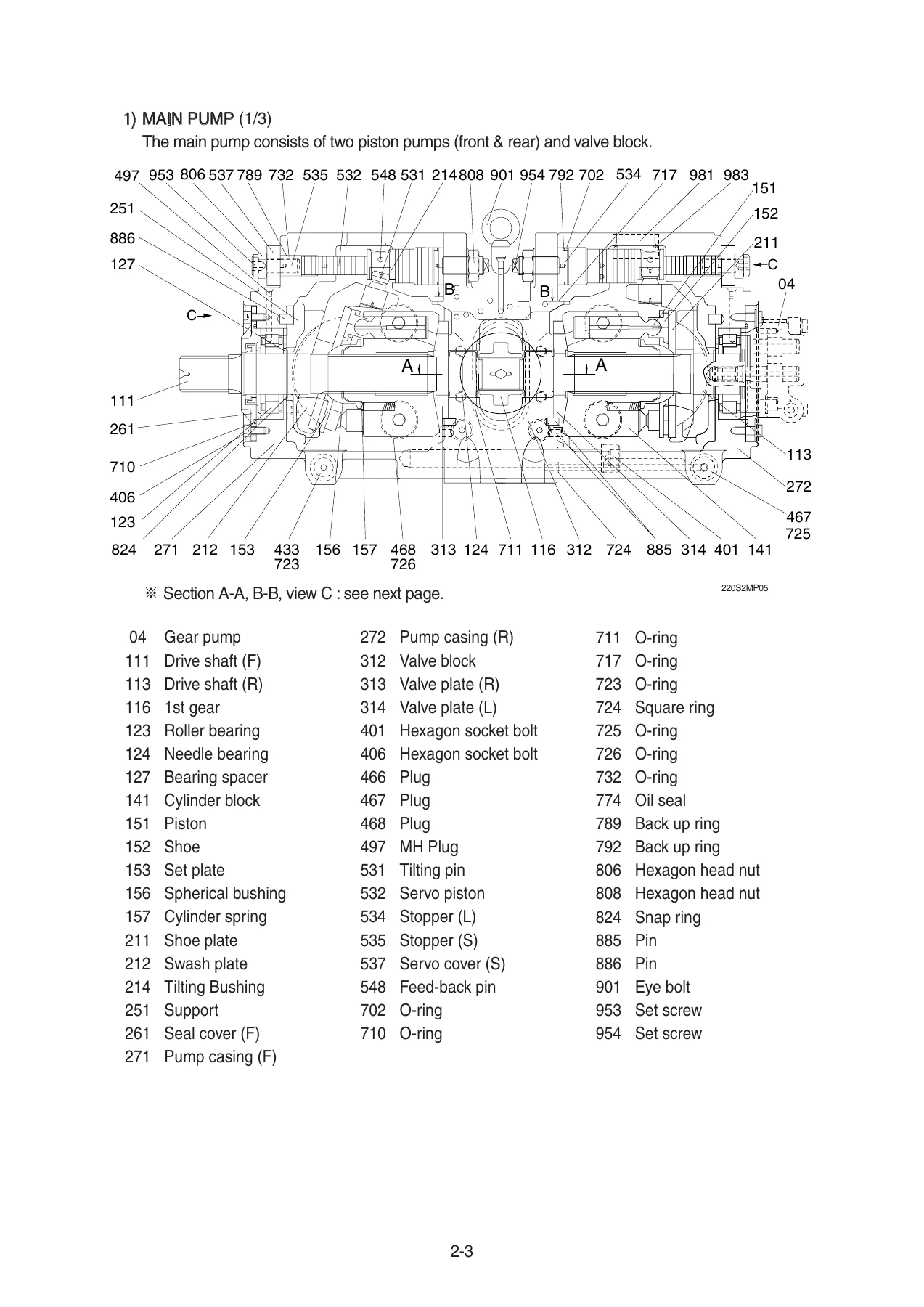
Section 3 explains the hydraulic circuit as a whole and then breaks it down into the main circuit, the pilot circuit, and the way single and combined operations are delivered. The structure-and-function section for the main control valve goes through each spool – travel straight, swing, boom 1, boom 2 and swing priority, arm 1, arm 2, arm regeneration, bucket, option, and the bypass cut spools – and shows how the holding valves, port relief valves, load check valves, negative control valve and swing logic valve interact. Combined-operation chapters cover swing with boom, swing with arm, swing with bucket, swing and travel, boom and travel, arm and travel, bucket and travel, boom up with bucket and boom up with arm, including the boom priority and swing priority logic that changes which function receives oil first. The pump section covers the tandem piston pump rotary group, swash plate group, valve block and PTO group, and the regulator’s negative flow control, horsepower control, power shift control and the priority mechanism for the lower tilting command.
Electrical and Mechatronics
Section 4 lays out component locations, the full electrical circuit diagrams and connector pin tables, with component specifications for relays, solenoids, sensors, EPPR valves, switches, lamps and the controllers. Section 5 carries the Advanced CAPO layer: power mode selection (P, S, E), work mode selection (general, breaker, crusher), user mode, auto deceleration, power boost, travel speed control, automatic warming up, engine overheat prevention, variable power control, attachment flow control, intelligent power control, anti-restart, and the self-diagnostic system with its full error code table. Fault codes are listed with their diagnostic criteria and the connector pins to check, so a code shown on the cluster can be traced to the wiring rather than guessed at. The monitoring section covers the cluster, gauges, warning lamps, pilot lamps, switches, main menu, mode setup, monitoring, management, display, utilities and the around-view monitoring system where fitted.
Troubleshooting, Maintenance Standards and Repair
Section 6 is the fault-finding core: a structured diagnostic procedure followed by dedicated troubleshooting charts for the hydraulic and mechanical system, the electrical system, and the mechatronics system. Typical entries cover unusual noise from the pump coupling, the machine not operating at all after start, cloudy or overheated hydraulic oil, cavitation, contaminated oil, swing and travel faults, weak or immovable boom, arm and bucket functions, drift in the dig function, low relief pressure and sensor or EPPR valve faults. Section 7 publishes the operational performance test procedures with standard and maximum allowable values – engine speed in each power mode, travel speed, track revolution speed, travel deviation, swing speed, swing drift, swing bearing play, cylinder cycle times, dig function drift, control lever operating force and stroke, pilot primary pressure, travel speed selecting pressure, swing parking brake releasing pressure, main pump delivery pressure and system relief settings. It also lists service limits and recommended replacement values for the main pump, main control valve, swing device, travel motor, RCV lever, RCV pedal, turning joint, cylinder, track roller, carrier roller, idler, track link, track frame, recoil spring and work equipment pins and bushings.
Disassembly and Assembly
Section 8 is the hands-on half of the manual. It opens with precautions for removal, installation and completing work, followed by a tightening torque table for major components and a general torque chart for bolts, nuts, pipe and hose fittings. Each component then gets its own procedure: the pump device, the regulator, the main control valve with its spools, relief valves, logic valves and holding valve, the swing motor and reduction gear, the travel motor and travel reduction gear, the RCV lever, the turning joint, the boom, arm and bucket cylinders, the undercarriage including track link, carrier roller, track roller, idler and recoil spring, and the work equipment including bucket, arm and boom removal and installation. Exploded views, cross-sections and labelled part numbers make the teardown sequence unambiguous, and where a specific tool, press, jig or torque is required it is called out on the page.
IMAGES PREVIEW
Why This Hyundai HX225S L Service Manual Matters
Repairing a 22-tonne excavator without the manufacturer’s own service data usually means guessing at relief pressures, hydraulic circuit logic, connector pinouts or bearing clearances, and guessing on this class of machine is expensive. A wrong main relief setting alters every function downstream. A misread fault code sends you into the wrong harness. A cylinder reassembled without the correct lock nut torque can back off under load. This manual removes that guesswork by supplying the exact figure, the exact sequence and the exact diagnostic path for the HX225S L and its Long Reach and High Walker variants.
What You Can Do With It
- Diagnose hydraulic faults with the machine-specific troubleshooting charts rather than generic advice
- Read and act on mechatronics fault codes using the diagnostic criteria and connector pin references
- Set up and verify engine, pump, relief, swing and travel performance against published test values
- Assess wear on pumps, valves, motors, cylinders, rollers, idlers and work equipment pins against service limits
- Rebuild the main pump, main control valve, swing motor, travel motor, cylinders and undercarriage to the correct torques and sequences
- Trace hydraulic and electrical circuits through full schematics, port tables and connector destination charts
- Understand how combined operations such as swing plus boom, or travel plus attachment, distribute pump flow on this machine
Instant PDF Delivery
The Hyundai HX225S L Hydraulic Excavator Service Manual is delivered as a PDF download immediately after payment – there is no shipping, no waiting and no physical book to lose in the workshop. The file opens on a laptop, desktop, tablet or smartphone, can be searched and zoomed on screen, and can be printed page by page if you prefer a paper copy at the machine. Keep it on a service laptop, load it onto a rugged tablet for field use, or print the sections you need for the job in front of you. It is a permanent reference you can return to every time an HX225S L comes into the shop.
Reviews
There are no reviews yet.