
Hyundai R140LC-7 R140LCD-7 R140LCM-7 Excavator Service Repair Manual PDF
Original price was: $39.95.$23.95Current price is: $23.95.
Complete Hyundai R140LC-7, R140LCD-7 and R140LCM-7 crawler excavator service repair manual in PDF. 574 pages covering hydraulic, electrical, mechatronics, disassembly, torque specs and full troubleshooting for the R140 series.
Description
Hyundai R140LC-7, R140LCD-7 and R140LCM-7 Excavator Service Repair Manual
This is the complete Hyundai R140LC-7 / R140LCD-7 / R140LCM-7 excavator service repair manual, supplied as an instant-download PDF. It is the same workshop document Hyundai technicians use to service, diagnose and rebuild the R140 series 14-ton class crawler excavator, and it covers every major system on the machine: pump device, main control valve, swing and travel devices, RCV lever and pedal, hydraulic circuit, electrical circuit, NEW CAPO mechatronics system and the full work equipment group.
Whether you are repairing a single leaking cylinder, rebuilding a travel motor, tracing an electrical fault in the Tier I or Tier II harness, or performing a full hydraulic performance test on an R140LC-7, this Hyundai R140 service manual contains the procedures, tolerances and torque values required to do the job correctly.
File Details
- Manual type: Service / Workshop Repair Manual
- Brand: Hyundai Heavy Industries Co., Ltd.
- Models covered: R140LC-7, R140LCD-7, R140LCM-7 (including the R140LC-7 2-piece boom variant)
- Engine: Cummins B3.9-C / 4BTA (Tier II)
- Language: English
- Pages: 574
- File format: PDF
- Serial breakpoints referenced: up to #0255, #0256 to #1000, #1001 and up (Tier II)
IMAGES PREVIEW
Chapters Covered
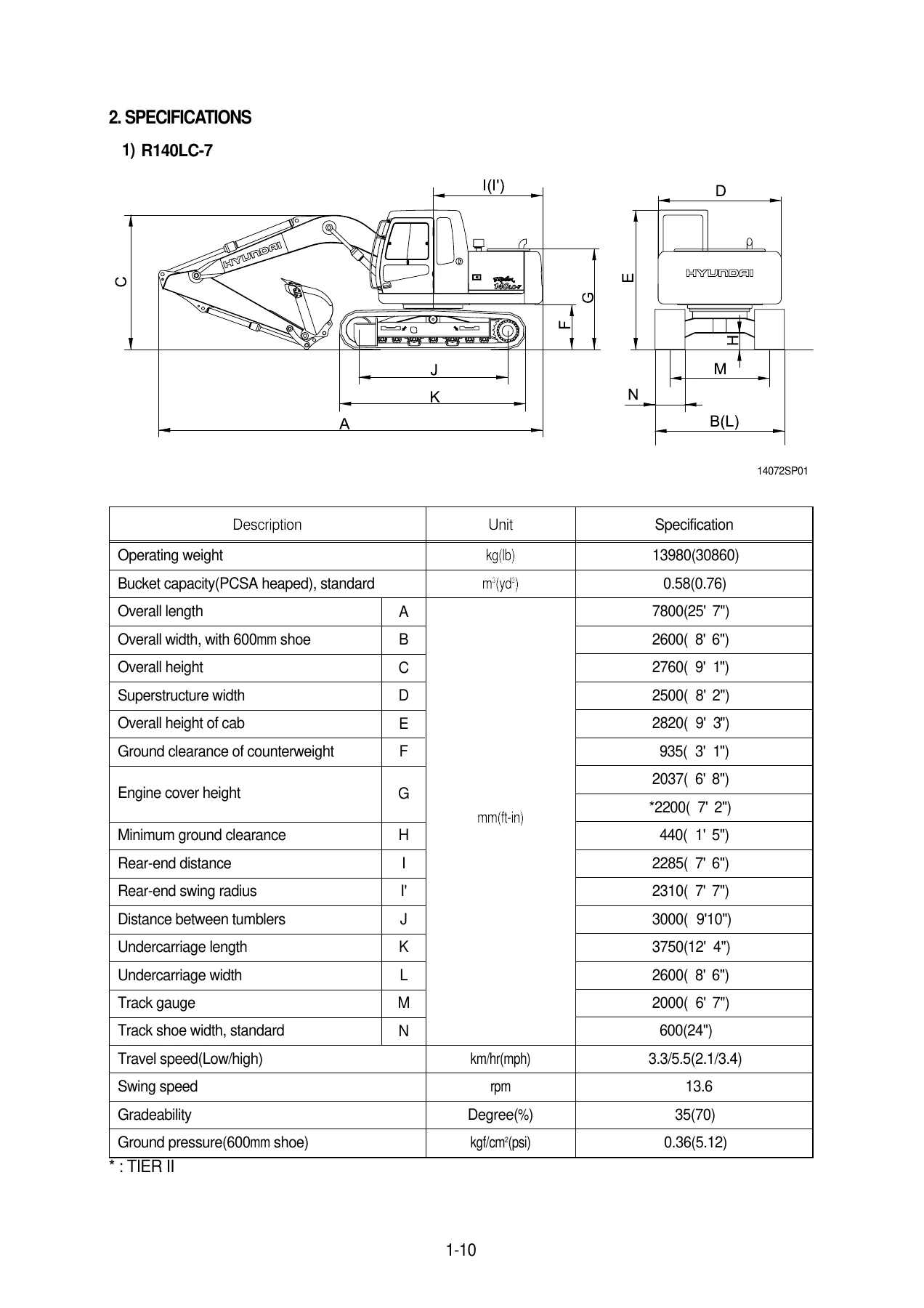
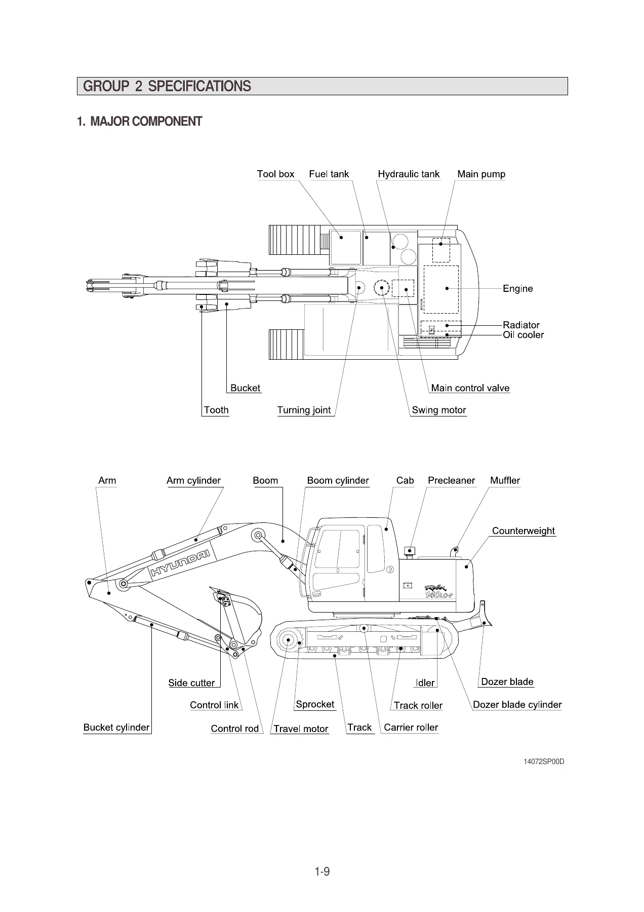
- Section 1 — General: safety, specifications, major components, working range, weight, lifting capacities, bucket selection guide, undercarriage, recommended oils
- Section 2 — Structure and Function: pump device, main control valve, swing device, travel device, RCV lever, RCV pedal
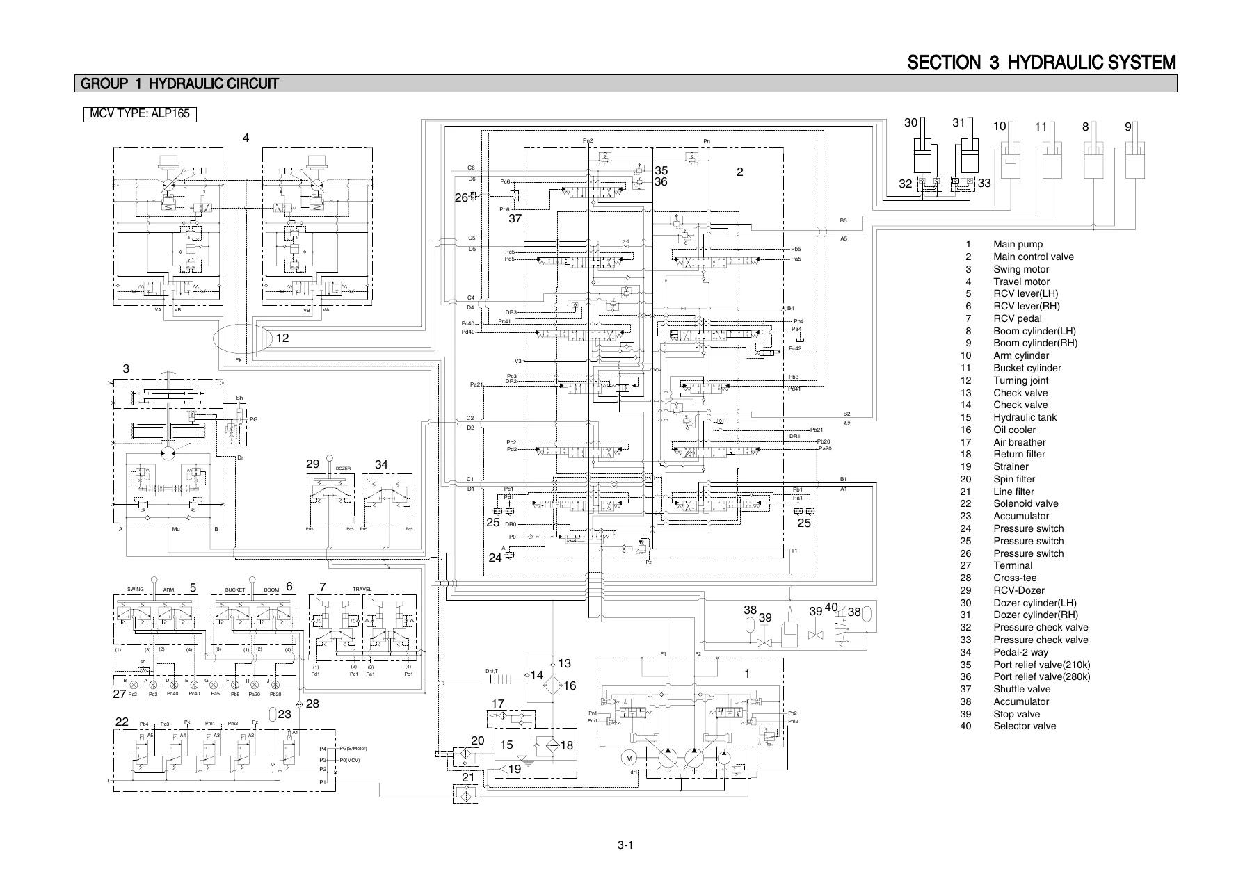
- Section 3 — Hydraulic System: hydraulic circuit, main circuit, pilot circuit, single operation, combined operation
- Section 4 — Electrical System: component location, electrical circuit (Tier I and Tier II variants), electrical component specification, connectors
- Section 5 — Mechatronics System: NEW CAPO outline, mode selection, automatic deceleration, power boost, travel speed control, automatic warming up, engine overheat prevention, anti-restart, self-diagnostic, engine control, EPPR valve, prolix switch, monitoring system
- Section 6 — Troubleshooting: hydraulic and mechanical system, electrical system, mechatronics system
- Section 7 — Maintenance Standard: operational performance test, major components, track and work equipment
- Section 8 — Disassembly and Assembly: precautions, tightening torque, pump device, main control valve, swing device, travel device, RCV lever, turning joint, boom / arm / bucket cylinder, undercarriage, work equipment
- Section 9 — Component Mounting Torque: engine system, electric system, hydraulic system, undercarriage, structure, work equipment
What the Hyundai R140LC-7 Service Manual Covers in Depth
The pump device group breaks down the tandem variable-displacement piston pump, the regulator and the gear pump, with the full negative flow control, total horsepower control, power shift control and Qmax cut functions explained step by step. Every adjustment — flow control characteristic, outer and inner spring, maximum and minimum flow, Qmax cut flow — is documented with the tightening amount and the resulting change in flow or torque. The main control valve group covers the 10-spool ALP165 / UHX22-26 valve, spool-by-spool flow paths, holding valves, negative control, main and port relief operation, foot relief, arm regeneration and the bucket flow summation circuit.
The swing device section covers the fixed-displacement axial piston motor, the 2-stage planetary reduction gear, the mechanical parking brake system, the time delay valve and the make-up valve. The travel device section covers the variable-displacement motor, brake valve, parking brake, high/low speed changeover mechanism and the planetary plus differential reduction gear, along with the full clearance selection procedure for the distance piece and thrust bearing.
The NEW CAPO mechatronics group walks through each mode selection, auto decel, power boost, travel speed control, warming up and overheat prevention function, then documents the CPU controller self-diagnostic system with the complete error code table (codes 1 through 58), the connector pin-outs and the monitoring display groups on the cluster.
Repairs, Diagnostics and Rebuilds This Manual Supports
This R140LC-7 / R140LCD-7 / R140LCM-7 repair manual is deep enough to support a full rebuild of the machine, not just routine maintenance:
- Hydraulic pump removal, disassembly and reassembly — cylinder block, pistons, shoes, set plate, swash plate group, valve block and regulator
- Main control valve disassembly and assembly — spools, holding valves, load check valves, negative relief valves, main relief, port relief, foot relief and arm regeneration valve
- Swing motor rebuild — cylinder assembly, cam plate, balance plate, brake piston and springs, time delay valve and make-up valve, plus reduction gear rebuild
- Travel motor rebuild — brake valve spool, check valves, two-speed control valve, parking brake section, hydraulic motor section and reduction gear assembly
- Boom, arm and bucket cylinder reseal and rebuild, with lock nut torque values and piston seal fitting direction
- Undercarriage work — track link, carrier roller, track roller, idler, recoil spring and tension adjustment
- Full electrical troubleshooting on the Tier I (up to #1000) and Tier II (#1001 and up) harnesses, plus the intermediate connector (CN-x) and Deutsch connector reference tables
- Mechatronics diagnostics — EPPR valve, accel actuator, engine speed sensor, CPU controller, cluster display codes and the full monitoring display menu
- Operational performance tests — engine speed, travel speed, track revolution, swing speed, swing drift, swing bearing play, cylinder cycle times, dig function drift, control lever operating force and stroke, pilot primary pressure, main pump delivery pressure and system relief pressure
Why a Correct Hyundai R140 Service Manual Matters
The R140 series is a computer-controlled machine. Engine speed, pump displacement, relief pressure and swing priority are all governed by the NEW CAPO system through the CPU controller and EPPR valve. Getting the pump regulator, relief setting or EPPR current wrong does not just cost performance — it can stall the engine, overheat the hydraulic oil, damage the travel motor or throw the machine into limp mode. The torque tables, service limits and measurement procedures printed in this Hyundai R140LC-7 workshop manual are the values the excavator was designed to be serviced to.
Instant PDF Delivery
This Hyundai R140LC-7, R140LCD-7 and R140LCM-7 excavator service manual is delivered as an instant-download PDF after payment. No shipping, no waiting for a disc, no dealer appointment. Read it on a laptop, tablet or smartphone in the workshop, print only the section you need, and keep it with the machine for the life of the excavator.
Reviews
There are no reviews yet.