

Hyundai R210-9 Excavator Workshop Service Manual
Original price was: $39.95.$24.95Current price is: $24.95.
Comprehensive workshop service manual for the Hyundai R210-9 crawler excavator. Covers full machine specifications, Advanced CAPO mechatronics, hydraulic schematic flow, electrical troubleshooting, connector pinouts, component overhaul, and bolt torque standards in a complete 566-page technical PDF download.
Description
Hyundai R210-9 Excavator Workshop Service Manual
This technical publication provides comprehensive workshop service instructions, operational theory, hydraulic schematics, electrical diagrams, and step-by-step mechanical overhaul procedures for the Hyundai R210-9 excavator. Designed specifically for heavy equipment technicians, field mechanics, and workshop specialists, this factory-level documentation provides exact pressure limits, circuit trace lines, sensor resistance values, mechatronic operational logic, and precision bolt torque values required to inspect, maintain, diagnose, and rebuild major excavator assemblies.
File Details
- Document Type: Workshop Service Manual / Shop Manual
- Brand: Hyundai Heavy Industries
- Applicable Equipment: R210-9 Crawler Excavator (including High Walker undercarriage variants)
- Serial Coverage: Serial No. -#0199 and #1289- onwards (including proportional control options)
- File Format: Portable Document Format (PDF)
- Total Page Count: 566 pages
- Language: English
- Publication/Part Number Reference: 661094312 / 21Q7-10910
Chapters Covered
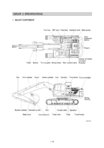
- SECTION 1 – GENERAL: Group 1 Safety Hints; Group 2 Specifications
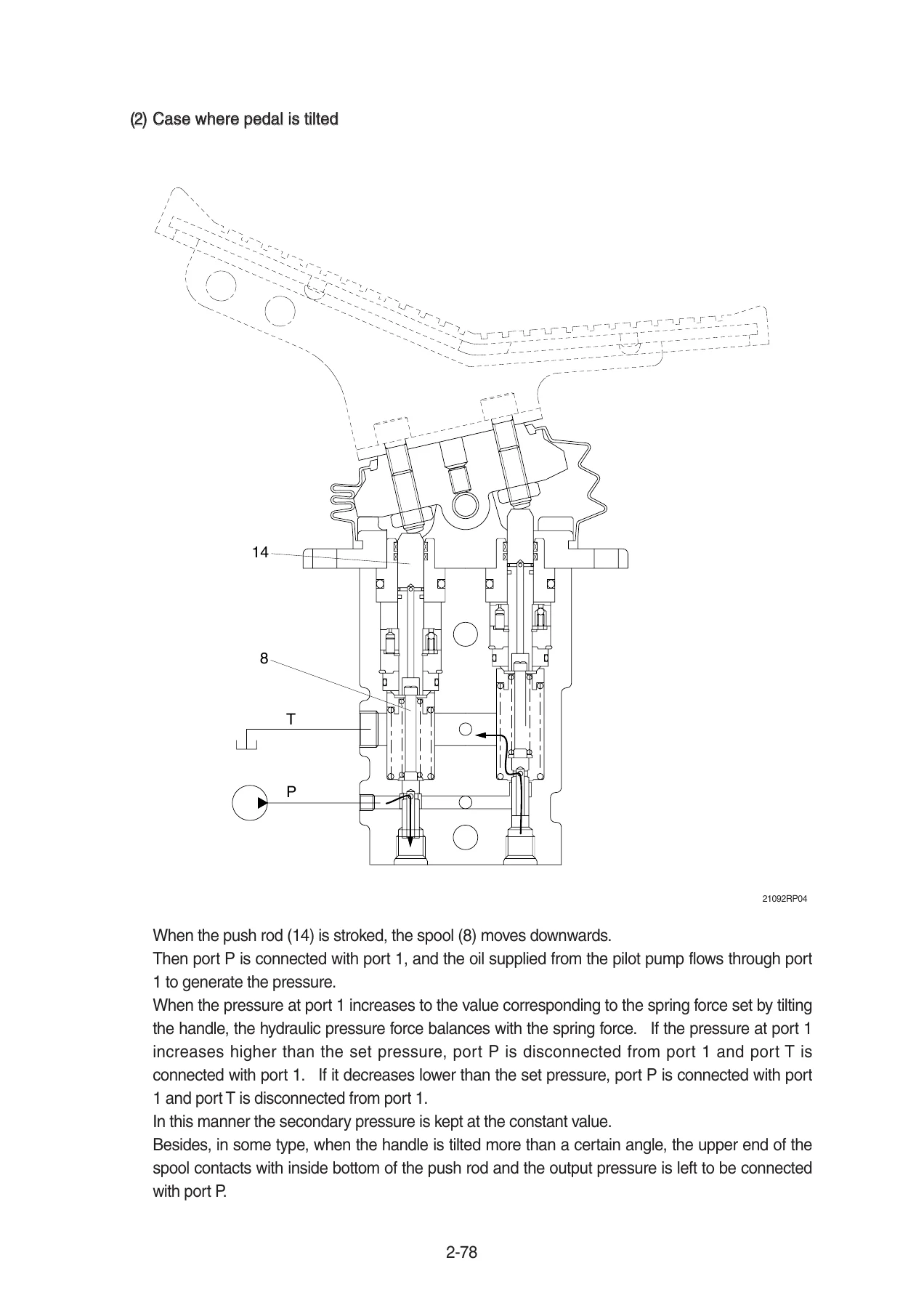
- SECTION 2 – STRUCTURE AND FUNCTION: Group 1 Pump Device; Group 2 Main Control Valve; Group 3 Swing Device; Group 4 Travel Device; Group 5 RCV Lever; Group 6 RCV Pedal
- SECTION 3 – HYDRAULIC SYSTEM: Group 1 Hydraulic Circuit; Group 2 Main Circuit; Group 3 Pilot Circuit; Group 4 Single Operation; Group 5 Combined Operation
- SECTION 4 – ELECTRICAL SYSTEM: Group 1 Component Location; Group 2 Electrical Circuit; Group 3 Electrical Component Specification; Group 4 Connectors
- SECTION 5 – MECHATRONICS SYSTEM: Group 1 Outline; Group 2 Mode Selection System; Group 3 Automatic Deceleration System; Group 4 Power Boost System; Group 5 Travel Speed Control System; Group 6 Automatic Warming Up Function; Group 7 Engine Overheat Prevention Function; Group 8 Variable Power Control System; Group 9 Attachment Flow Control System; Group 10 Anti-Restart System; Group 11 Self-Diagnostic System; Group 12 Engine Control System; Group 13 EPPR Valve; Group 14 Monitoring System; Group 15 Fuel Warmer System
- SECTION 6 – TROUBLESHOOTING: Group 1 Before Troubleshooting; Group 2 Hydraulic and Mechanical System; Group 3 Electrical System; Group 4 Mechatronics System
- SECTION 7 – MAINTENANCE STANDARD: Group 1 Operational Performance Test; Group 2 Major Components; Group 3 Track and Work Equipment
- SECTION 8 – DISASSEMBLY AND ASSEMBLY: Group 1 Precaution; Group 2 Tightening Torque; Group 3 Pump Device; Group 4 Main Control Valve; Group 5 Swing Device; Group 6 Travel Device; Group 7 RCV Lever; Group 8 Turning Joint; Group 9 Boom, Arm and Bucket Cylinder; Group 10 Undercarriage; Group 11 Work Equipment
- SECTION 9 – COMPONENT MOUNTING TORQUE: Group 1 Introduction Guide; Group 2 Engine System; Group 3 Electric System; Group 4 Hydraulic System; Group 5 Undercarriage; Group 6 Structure; Group 7 Work Equipment
Together, these nine comprehensive sections equip workshop engineers with an end-to-end service reference, bridging operational system theory with practical workshop teardown, component measurement, fault diagnosis, and structural reassembly.
Hydraulic Architecture & Pilot Circuit Operation
The manual provides thorough technical coverage of the main hydraulic and pilot circuits. It details the swash plate type variable displacement axial piston main pump driven at an engine ratio of 1.0, suction line filtering, actuator return circuitry, and oil cooler flow. Technical specifications cover return circuit bypass check valves rated at 1.5 kgf/cm² (21 psi) and 3.0 kgf/cm² (43 psi), full-flow tank filter bypass relief set to 1.5 kgf/cm², and motor drain line filtration. In the pilot circuit, the gear-driven pilot pump is documented with its integral 40 kgf/cm² relief valve, safety lock solenoid valve operation, swing parking brake release via the SH port, travel speed shift mechanisms, and boom priority EPPR systems. Step-by-step schematics explain oil confluence, straight travel spool actuation, arm regeneration cut systems, and combined operations including swing with boom up, arm, bucket, and travel.
Advanced CAPO Mechatronics & Engine Control
Technicians will find extensive analysis of the Computer Aided Power Optimization (Advanced CAPO) system. The service manual covers the microcomputer-based interaction between the Machine Control Unit (MCU), the engine Electronic Control Module (ECM), and the operator cluster monitor. Mode selection documentation details Power Modes (P, S, E) and customizable User Mode (U) parameters, including EPPR valve pilot pressure shifts ranging from 0 to 35 kgf/cm² and current control from 100 to 700 mA. Automatic deceleration functions reduce engine speed to 1000 rpm after 4 seconds of control lever neutral position and down to 850 rpm after 60 seconds. Digging performance enhancements, such as one-touch power boost (elevating main relief pressure from 350 kgf/cm² to 380 kgf/cm² for a maximum of 8 seconds), variable power control, automatic warming up thresholds (under 30°C coolant), and two-stage engine overheat protection logic (100°C, 103°C, and 105°C thresholds), are fully mapped with operational flowcharts and logic tables.
Electrical Schematics, Diagnostics & Connector Pinouts
Electrical servicing is supported by complete cabin, console, engine, and frame wiring schematics. The electrical section details circuit paths for power distribution, starter lockout, preheat relays, alternator charging, cluster communications, and work lights. A full diagnostic section provides fault code identification across both machine HCESPN codes and Cummins ECM diagnostic trouble codes, detailing active/logged fault retrieval, failure mode identifiers (FMI), and causes. Furthermore, the manual features dedicated connector tables detailing terminal configurations, part numbers, and pinouts for AMP, Deutsch DT/DRC, Molex, KET, and Yazaki connectors, alongside bench testing specifications for relays, sensors, potentiometers, solenoid valves, and switches.
IMAGES PREVIEW
Component Disassembly, Cylinder Overhaul & Undercarriage Rebuild
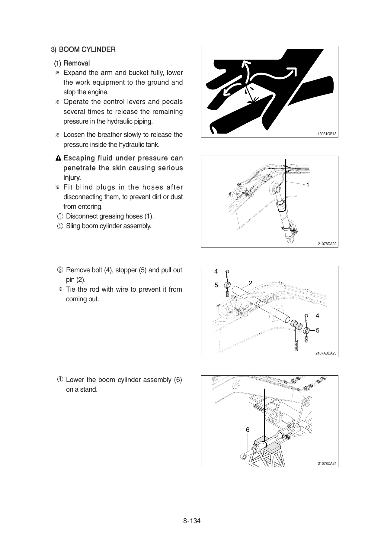
Practical mechanical overhauls are guided by detailed, sequential disassembly and assembly instructions. Technicians are provided with complete rebuild procedures for the boom, arm, and bucket hydraulic cylinders, including seal replacement, cushion ring orientation, gland torque, and piston lock nut tightening (ranging from 100±10 kgf·m on bucket cylinders to 200±20 kgf·m on boom cylinders). Remote Control Valve (RCV) hand levers and foot pedals are broken down to individual spools, push rods, cams, and return springs. The turning joint overhaul section details slipper seal and O-ring replacement, while the undercarriage section outlines track link splitting, carrier and track roller removal, idler press work, and recoil spring disassembly under its 13,716 kg (30,238 lb) pre-load setting. Metric component mounting torque tables cover every critical fastener from M6 cabin hardware to M36 counterweight bolts (340±10 kgf·m / 2460±72.3 lbf·ft).
Capability, Precision & Fast Delivery
Owning the Hyundai R210-9 Excavator Workshop Service Manual allows mechanics and equipment owners to perform factory-standard repairs in-house, avoiding expensive dealership labor and unnecessary downtime. Utilizing exact hydraulic pressures, electrical terminal paths, and manufacturer bolt torque values prevents catastrophic structural failures, premature pump wear, and electronic control errors. Available as an instant PDF download, this digital technical manual is fully compatible with Windows, Mac, iPad, tablet, and smartphone devices, and can be printed in whole or by section for immediate workshop and job site reference.
Reviews
There are no reviews yet.