
Isuzu F and G Series 6HK1 Engine Control System Workshop Manual 2008-2009
Original price was: $34.95.$22.95Current price is: $22.95.
Complete 392-page Isuzu engine control system workshop manual for 2008/2009MY F and G Series trucks with the 6HK1 engine. Covers ECM wiring, sensor and actuator diagnostics, full DTC procedures, scan tool data, DPD system checks and SPS programming.
Description
Isuzu F and G Series 6HK1 Engine Control System Workshop Manual
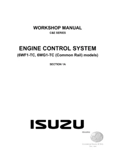
This Isuzu F and G Series 6HK1 Engine Control System Workshop Manual is the complete service documentation for the electronic engine management system used on 2008 and 2009 model year F and G Series trucks equipped with the 6HK1 diesel engine. Published by Isuzu Motors Limited in July 2008 as a Third Edition, this 392-page PDF covers everything a technician needs to diagnose, test, and repair the engine control system — from wiring diagrams and connector end views through to full DTC diagnostic procedures, symptom charts, and ECM replacement with Service Programming System (SPS) instructions.
File Details
- Manual Type: Engine Control System Workshop Manual
- Brand / Model: Isuzu F and G Series (6HK1 engine)
- Document Number: MG6HKED-WE-0871
- Edition: Third Edition
- Published: July 2008
- Language: English
- Page Count: 392
- File Format: PDF
- Coverage: 2008/2009MY Isuzu F and G Series with 6HK1 engine
Chapters Covered
- General Information
- Engine Control System (Section 1A)
- Specifications — Temperature vs Resistance tables for engine coolant temperature, exhaust temperature, fuel temperature and intake air temperature, plus altitude vs barometric pressure
- Diagnostic Trouble Code (DTC) Type Definitions — Type A, B, C and D
- Diagnostic Trouble Code (DTC) List — full DTC and flash code table
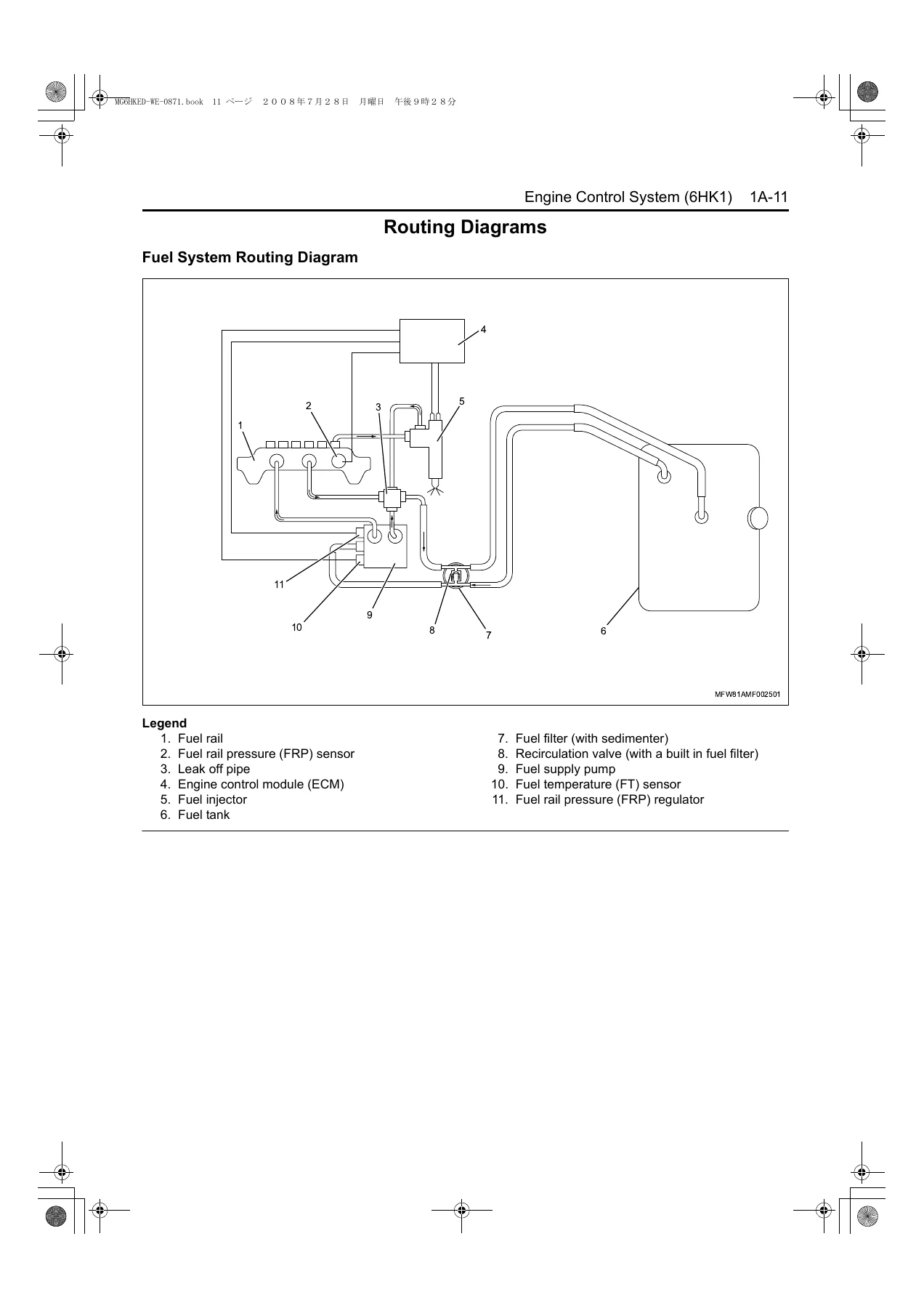
- Routing Diagrams — fuel system routing
- Component Locator — engine controls component views, ECM, sensors, actuators
- ECM Connector End Views
- Engine Control Connector End Views — APP, BARO, boost pressure, brake switches, CMP, CKP, cruise control, DLC, EGR, exhaust differential pressure, exhaust temperature, exhaust throttle, fuel injectors, FRP regulator, FRP sensor, FT sensor, glow plug, MAF/IAT, intake throttle, idle up, PTO throttle, REA and VSS
- Diagnostic Information and Procedures — Engine Control System Check Sheet, Diagnostic Starting Point, Reading Flash DTCs, DTC Clear Method by Accelerator Pedal Operation
- Diagnostic System Check — Engine Controls (Euro 4 and Except Euro 4)
- Scan Tool Data List and Scan Tool Data Definitions
- Scan Tool Output Controls
- Scan Tool Does Not Power Up
- Scan Tool Does Not Communicate with CAN Device (Euro 4)
- Scan Tool Does Not Communicate with Keyword Device (Except Euro 4)
- Lost Communication with ECM (Except Euro 4)
- Engine Cranks but Does Not Run
- Full DTC diagnostics from P0016 through U0167
- EGR Control System Check
- Glow Control System Check
- Exhaust Brake Control System Check
- Cruise Control System Check
- Diesel Particulate Defuser (DPD) Control System Check
- Symptoms — Hard Start, Rough/Unstable/Incorrect Idle and Stalling, High Idle Speed, Cuts Out, Surges, Lack of Power/Sluggishness/Sponginess, Hesitation/Sag/Stumble, Abnormal Combustion Noise, Poor Fuel Economy, Excessive Black Smoke, Excessive White Smoke, DPD Manual Regeneration Frequently, DPD Regeneration Long Time
- Repair Instructions — ECM replacement and Service Programming System procedures
- Description and Operation — ECM, APP sensor, BARO sensor, boost pressure sensor, CMP sensor, CKP sensor, ECT sensor, FT sensor, IAT sensor, MAF sensor, fuel system, EGR system, turbocharger and DPD system
- Special Tools and Equipment
What This Manual Gives a Technician
The 6HK1 engine control system is a fully electronic common rail diesel management platform, and this manual is built around the ECM and its entire sensor and actuator network. Every diagnostic procedure follows the same disciplined structure — circuit description, conditions for running the DTC, conditions for setting the DTC, action taken when the DTC sets, conditions for clearing, diagnostic aids, connector end view references, and a step-by-step circuit/system testing table with values and Yes/No routing. That structure is what turns a fault code into a repair rather than a guess.
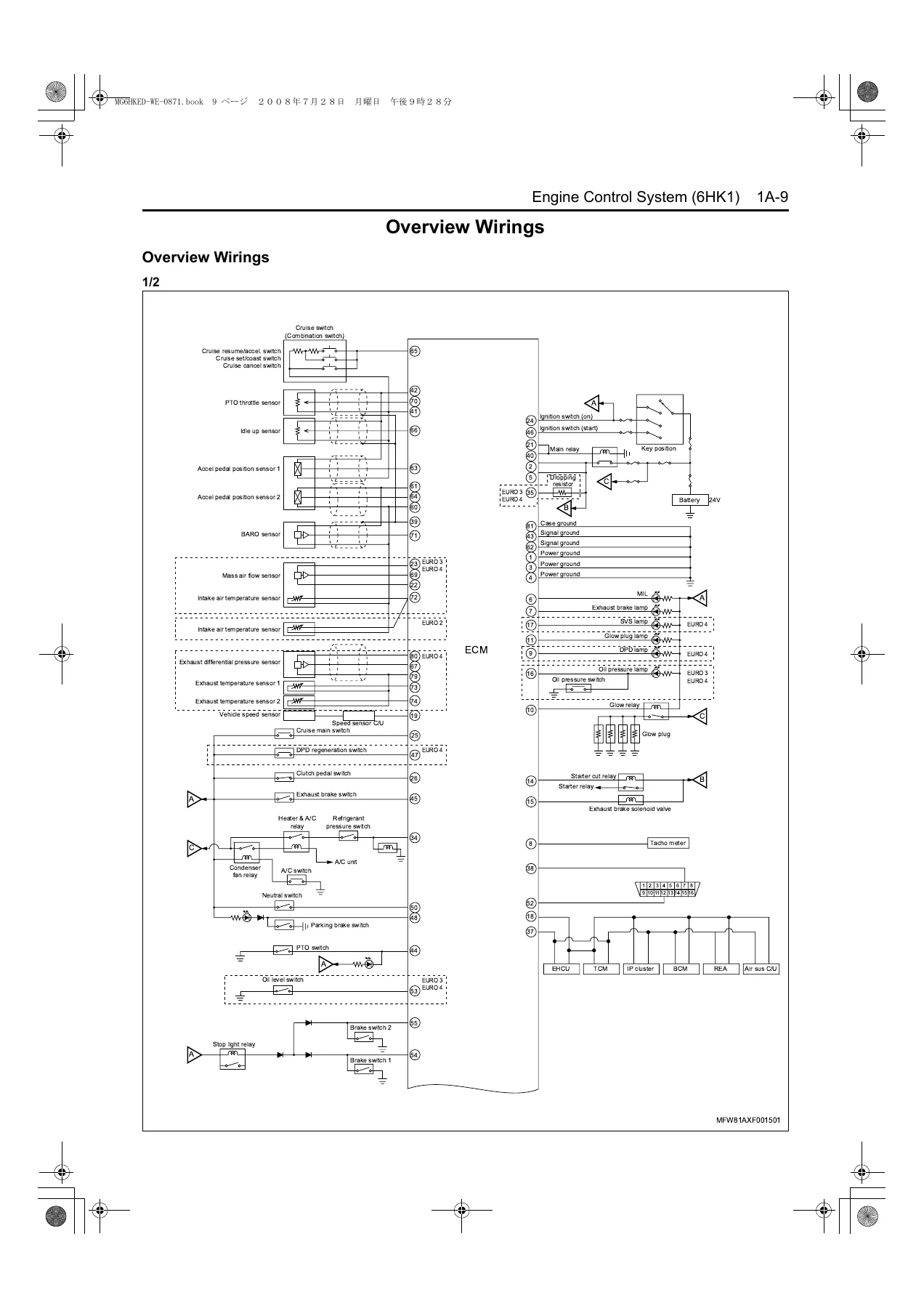
The wiring diagrams and ECM connector end views are a core part of the manual. The document provides the ECM pinout for connectors FB24 and E26, the engine control connector end views for every major sensor and actuator on the 6HK1, and the fuel system routing diagram. Having the correct terminal numbers, wire colours, and circuit functions in front of you is the difference between a clean back-probe and a damaged harness.
Diagnostic Coverage in Detail
The DTC list spans the full engine management system, including crankshaft and camshaft correlation (P0016), turbocharger boost control (P0045), exhaust throttle solenoid (P0079/P0080), fuel rail pressure faults (P0087, P0088, P0089, P0091, P0092, P0093, P1093), mass air flow (P0101/P0102/P0103), boost pressure (P0107/P0108), intake air temperature (P0112/P0113), engine coolant temperature (P0116/P0117/P0118), throttle position (P0122/P0123), fuel temperature (P0182/P0183), fuel rail pressure sensor (P0192/P0193), injector circuits (P0201–P0206), engine over-temperature (P0217), engine overspeed (P0219), turbocharger overboost and underboost (P0234/P0299), crankshaft position (P0335/P0336), camshaft position (P0340/P0341), glow plug and glow plug lamp (P0380/P0381), EGR flow and position (P0401/P0404/P0409/P1404), exhaust temperature sensors (P0426, P0427, P0428, P042B, P042C, P042D), vehicle speed sensor (P0500/P0502/P0503), system voltage (P0560/P0563), brake switch (P0571), ECM internal faults (P0601, P0602, P0604, P0606, P060B), immobilizer (P0633, P161B, U0167), intake throttle (P0638), 5V reference circuits (P0641, P0651, P0697), MIL and SVS lamp control (P0650, P1664), ECM main relay (P0685/P0687), injector charge voltage (P1261/P1262, P2146/P2149), DPD system (P1455, P1471, P242F, P2452, P2453, P2454, P2455, P2456, P2458), APP sensor (P2122, P2123, P2127, P2128, P2138), BARO sensor (P2227, P2228, P2229), PTO sensor (P253A), idle up sensor (P256A), and CAN communication faults (U0073, U0101, U0110).
Each of those DTCs has its own circuit/system testing table with the exact pin numbers to probe, the expected voltage or resistance, and the repair path if the reading is out of range. There is no filler here — this is the same diagnostic logic the service procedures are built around.
System Checks and Symptom Charts
Beyond individual DTCs, the manual includes dedicated system checks for the EGR control system, glow control system, exhaust brake control system, cruise control system, and the DPD control system. The symptom charts cover hard start, rough/unstable idle, high idle speed, cuts out, surges, lack of power, hesitation/sag/stumble, abnormal combustion noise, poor fuel economy, excessive black smoke, excessive white smoke, DPD manual regeneration frequency, and DPD regeneration long time.
Programming and Replacement
The ECM replacement procedure walks through the full A–G workflow: uploading fuel injector ID codes, retrieving ID codes from a non-communicating ECM, resetting and programming immobilizer security information, removal and installation, programming software and calibrations via the Service Programming System, programming injector ID codes and VIN, and performing the fuel supply pump relearn. Both the Remote Procedure and Pass-Thru Procedure for SPS are documented in full.
Who This Manual Is For
This Isuzu F and G Series 6HK1 Engine Control System Workshop Manual is aimed at technicians, fleet maintenance shops, and owners who need to diagnose and repair the electronic engine management system on 2008 and 2009 F and G Series trucks. It is a section-level workshop manual — Section 1A Engine Control System — not a full vehicle service manual, so it covers the engine control system in depth rather than the whole truck. If you are chasing a fault code, testing a sensor circuit, replacing an ECM, or trying to understand how the DPD regeneration system is meant to behave, this is the document that tells you what the ECM expects to see and what to do when it doesn’t see it.
IMAGES PREVIEW
With instant PDF delivery, no shipping, and the ability to print the pages you need or keep the whole manual on a laptop or tablet in the workshop, this Isuzu 6HK1 engine control system manual is a practical reference you can use the moment it lands in your inbox. Get the correct procedures and specifications the first time — download your copy today.
Reviews
There are no reviews yet.