
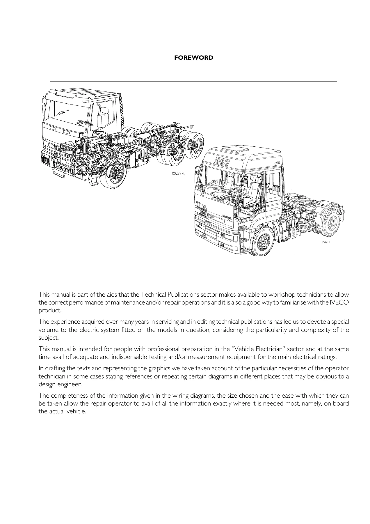
Iveco EuroTrakker EuroTech EuroStar Cursor 8 10 13 Electrical System Repair Manual
Original price was: $39.95.$24.95Current price is: $24.95.
376-page IVECO electrical system repair manual for EuroTrakker, EuroTech, and EuroStar trucks with Cursor 8, 10, and 13 engines. Covers ABS/EBS, EDC, ECAS, immobilizer, wiring diagrams, connector pinouts, and diagnostic procedures. Instant PDF download.
Description
Iveco EuroTrakker EuroTech EuroStar Cursor 8 10 13 Electrical System Repair Manual
This Iveco EuroTrakker EuroTech EuroStar Cursor 8 10 13 Electrical System Repair Manual is a comprehensive 376-page workshop publication covering the complete electric and electronic systems fitted to these IVECO heavy vehicle models. Published in July 2002 under publication number 603.93.121, it provides technicians with the circuit architecture, component data, connector pinouts, and diagnostic procedures needed to maintain and repair the electrical systems on EuroTrakker, EuroTech, and EuroStar trucks equipped with Cursor 8, Cursor 10, or Cursor 13 engines.
File Details
- Manual Type: Electrical/Electronic System Repair Manual
- Brand: IVECO
- Models: EuroTrakker, EuroTech, EuroStar
- Engines: Cursor 8, Cursor 10, Cursor 13
- Publication Number: 603.93.121
- Publication Date: July 2002
- Language: English
- Page Count: 376
- File Format: PDF
Chapters Covered
- Chapter I — Introduction: General cautions for electric/electronic components; concept of earth and electromagnetic compatibility; CAN line concept; technical codes; graphic symbols and abbreviations; electric diagrams of components including alternator, starter motor, battery, relays, switches, senders, sensors, solenoid valves, and electronic control units.
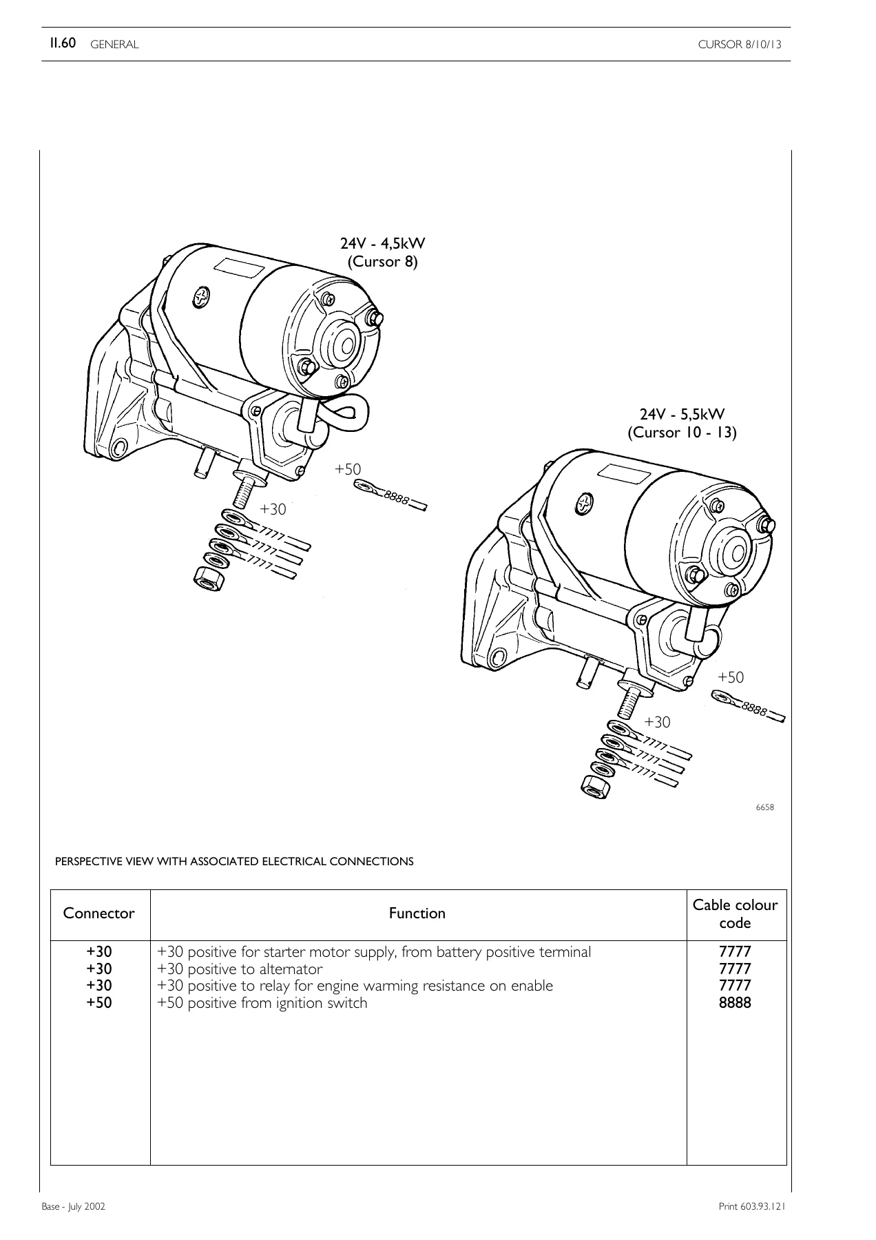
- Chapter II — General Description: Base system description; technical and electric specifications; cab structure; Cursor engine description for F2B (Cursor 8), F3A (Cursor 10), and F3B (Cursor 13); frame structure; complete vehicle with cab tilted; vehicle transparency; negative network and earth points on the vehicle; positive network and starting circuits; main components including the main control unit (UCI), dashboard and instrument clusters, starter motor, alternator, steering wheel stalk unit, ignition switch, front wall connectors (A through H, J, K, T), rear wall connectors, and cable connector codes (ST 01 through ST 82).
- Chapter III — Specific Circuits: ABS/EBS anti-lock brake system including ASR anti-slip regulator and EBL electronic brake limiter; EDC MS 6.2 electronic diesel control including pump injectors, VGT solenoid valve, pre/post-heating resistance, and engine brake; ECAS electronically controlled air suspension including level sensors, load sensing valves, electropneumatic distributors, and added axle management; immobilizer anti-theft system including ICU, antenna, electronic keys, and Code Card.
- Chapter IV — Circuit Charts: Over 57 detailed wiring diagrams covering start-up from driver’s seat, start-up from engine compartment, pre-heating, instruments (fuel level, water temperature, engine oil and brake air pressure, tachograph, rev counter), warning lights, sidelights, main/dipped beam headlights, additional headlights and rear foglights, brake lights, reverse light, horn, windscreen wiper, interior lighting, rearview mirrors, window winders, ABS/ASR, EBS, EDC, manual and automatic climate control, additional air heating, independent heating unit, main remote control switch, ADR electronic main remote control switch, air TMP emergency switch, ground startup and recharge, 15-pole socket, 2×7 pole socket, heated windscreen, drier heating, trip computer, electronic speedometer, hour counter, Economy Power, central door lock, Multipower takeoff, beacon lights, sunroof, central lubrication, hydraulic power steering, headlight washer, trailer braking system, immobilizer, Intarder ZF, and ECAS for various configurations.
This Iveco EuroTrakker EuroTech EuroStar Cursor 8 10 13 repair manual is structured specifically for workshop technicians with professional training in the vehicle electrician sector. The wiring diagrams are presented at a size and clarity that allows them to be used directly on the vehicle, with cable colour codes, connector references, component codes, and earth point identifiers clearly marked throughout.
Systems and Components Covered in Detail
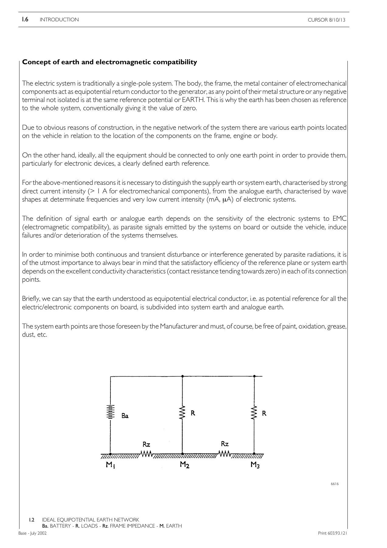
The manual provides in-depth coverage of the electronic control units and their communication networks. The CAN line architecture is explained, showing how the EDC, ABS/EBS, ECAS, Eurotronic transmission, and Immobilizer control units exchange data. The concept of system earth versus analogue earth is covered, along with the electromagnetic compatibility requirements that must be respected when repairing or installing additional equipment.
The ABS/EBS section explains the operation of the anti-lock braking system, the ASR anti-slip regulator, and the EBL electronic brake limiter. It includes the wiring diagrams, component descriptions, and diagnostic blink codes for both ABS and EBS systems. The rear axle electro-pneumatic modulator, the proportional relay valve for the front axle, the trailer control servodistributor, and the duplex distributor with electric transmitter are all described with their pneumatic and electric connections.
The EDC MS 6.2 section covers the electronic diesel control system for Cursor 8, 10, and 13 engines. It includes the control unit pinouts for connectors A (engine) and B (cab), the pump injector replacement procedure including the control unit re-programming code, the VGT solenoid valve control diagram, the pre/post-heating resistance operation, and the engine brake system with its control modes. Diagnostic blink code tables are provided for identifying faults through the EDC warning lamp.
The ECAS section describes the electronically controlled air suspension system, including the level sensors, load sensing valves, air suspension pressure low manometer switch, signal amplifier, and the various electropneumatic distributors used on different vehicle configurations (4×2, 6×2, 6×4). The remote control unit functions for lifting, lowering, levelling, and memorising frame positions are explained, along with the added axle lifting and aid at take-off procedures.
The immobilizer section covers the anti-theft system components: the Immobilizer Control Unit (ICU), the antenna on the ignition switch, the electronic keys with transponder, and the Code Card with electronic and mechanical codes. The emergency starting procedure using the electronic code via the accelerator pedal is described, along with key learning and actuator learning procedures.
Diagnostic Procedures
The manual includes comprehensive diagnostic information for the major electronic systems. Blink code activation and reading procedures are provided for the EDC system, the ABS system, the EBS system, and the ECAS system. The 30-pole diagnostic connector pinout is included, showing the connections for EDC, ABS/ASR/EBS, Retarder, SIB, Eberspaecher/Wabco, auxiliary units, Immobilizer, climate control, ECAS suspension, Eurotronic/Allison transmission, and EOL Eurotronic/Intarder.
The diagnostic tools referenced in the manual include MODUS (computerized diagnosis station), IVECO WIRING TESTER, and IT 2000 (portable diagnosis instrument). The manual explains the capabilities of each tool for fault identification, component activation, system parameter reading, and electronic control unit programming.
Safety Cautions and Best Practices
The introduction provides essential safety cautions for working with electric and electronic components. These include never disconnecting batteries with the engine running, always disconnecting the frame earth cable first, not using quick chargers to start the engine, using only appropriate measuring equipment, disconnecting electronic control units during electric welding, and protecting components from water jets. The manual also explains the importance of proper earth connections, the star connection of negative cables, and the correct routing of screened cables.
Why This Manual Is Essential
Electrical faults on modern heavy trucks can be difficult to diagnose without accurate wiring diagrams and component data. This Iveco EuroTrakker EuroTech EuroStar electrical repair manual eliminates guesswork by providing the complete circuit architecture, connector pinouts, component locations, and diagnostic procedures for these vehicles. Whether you are troubleshooting a starting circuit, repairing a lighting fault, diagnosing an ABS/EBS issue, or servicing the ECAS air suspension, this manual gives you the information needed to perform the repair correctly and efficiently.
The manual is particularly valuable because it covers the interaction between multiple electronic systems via the CAN network, which is essential for understanding how faults in one system can affect others. The inclusion of earth point locations, cable colour codes, and connector identification throughout the wiring diagrams makes it possible to trace circuits accurately and make reliable repairs.
Delivery
IMAGES PREVIEW
This Iveco EuroTrakker EuroTech EuroStar Cursor 8 10 13 Electrical System Repair Manual is available as an instant PDF download. After purchase, you receive immediate access to the complete 376-page document. There is no shipping, no waiting for a physical book, and no restrictions on viewing. The PDF can be accessed on any computer, tablet, or smartphone, and individual pages or circuit charts can be printed for use in the workshop. The digital format allows you to search for specific cable codes, component numbers, or connector references quickly, making it a practical tool for both routine maintenance and complex electrical repairs.
Reviews
There are no reviews yet.