
Iveco Trakker Repair Manual 603.93.371 – Complete Workshop PDF Download
Original price was: $79.95.$49.95Current price is: $49.95.
The complete Iveco Trakker Repair Manual 603.93.371 – over 1,800 pages of factory workshop procedures, torque data, overhaul instructions and diagnostics for the full Trakker truck range. Instant PDF download.
Description
Iveco Trakker Repair Manual 603.93.371 — Complete Truck Workshop PDF
The Iveco Trakker Repair Manual 603.93.371 is the full workshop reference for the Trakker heavy-duty truck range, produced by IVECO S.p.A. Customer Service through its Technical Publishing division in Torino. This is not a slimmed-down owner’s booklet — it is the same multi-section repair manual the Iveco commercial and assistance network uses when performing major mechanical, hydraulic, pneumatic and electrical work on Trakker vehicles. Every section is written for a qualified technician who needs the correct removal sequence, assembly clearance, tightening torque or fault chart on the bench, not a generalised description of how a truck works.
The manual runs to more than 1,800 pages across sixteen sections, with a base edition dated October 2004 and a November 2005 revision covering the Cursor engine family and the EuroTronic automated transmission. It is supplied here as a single high-quality PDF, ready to open on a laptop in the workshop, a tablet on the pit, or to print out the pages you need for the job in front of you.
File Details
- Manual type: Repair Manual (workshop / service)
- Brand: Iveco
- Model: Trakker
- Document number: 603.93.371 / 603.93.371/A
- Edition: Base — October 2004; revised November 2005
- Language: English
- Page count: 1,800+ pages
- File format: PDF
- Publisher: IVECO S.p.A. Customer Service — B.U. Technical Publishing, Lungo Stura Lazio 15, 10156 Torino, Italy
Trakker Models and Engines Covered
The manual covers the full Trakker line across the configurations sold in the 2004–2005 window, in both AD (short cab / Active Day) and AT (Long cab / Active Time) variants. The model tables at the front of the manual list rigid chassis-cabs, tractors and concrete mixer variants with their wheelbases, rear axle types and suspension configurations.
Wheel configurations covered include: 4×2, 4×4, 6×4, 6×6, 8x4x4, 8x8x4 and 8×8.
Trakker model designations listed in the composition tables include: AD 190 T, AT 190 T, AD 260 T, AT 260 T, AD 380 T, AT 380 T, AD 400 T, AT 400 T, AD 410 T, AT 410 T, AD 440 T, AT 440 T, AD 720 T and AT 720 T families, in the various power ratings (27, 31, 35, 38, 44 and 48).
Engines covered in the engine sections:
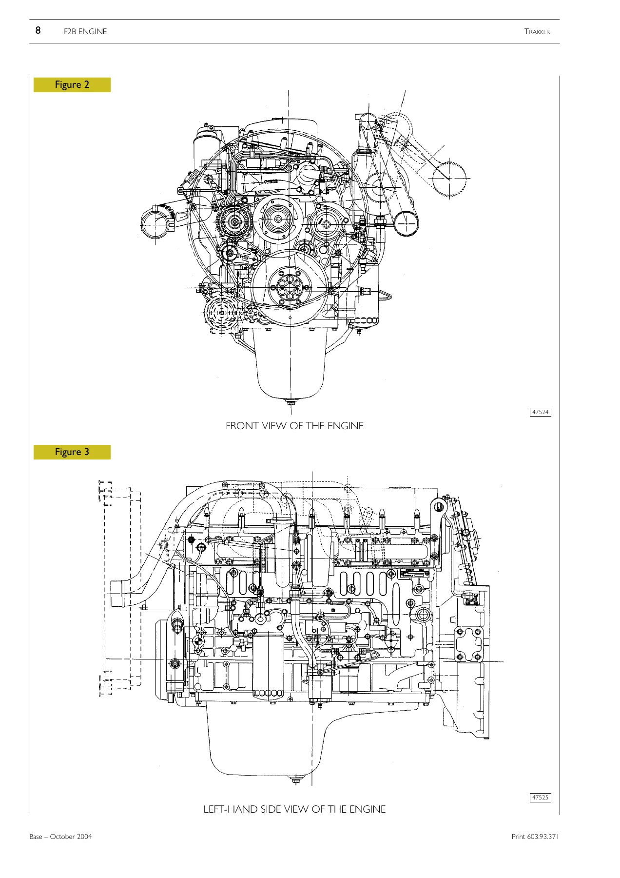
- F2B — 6-cylinder in-line, 115 mm bore × 125 mm stroke, 7,790 cm³ displacement. Ratings covered: F2BE0681F (270 HP / 200 kW), F2BE0681B (310 HP / 228 kW) and F2BE0681A (350 HP / 259 kW).
- F3B — 6-cylinder in-line, 135 mm bore × 150 mm stroke, 12,880 cm³ displacement. Ratings covered: F3BE0681G (380 HP / 280 kW), F3BE0681C (440 HP / 324 kW) and F3BE0681E (480 HP / 353 kW).
Chapters Covered
- Section 1 — General Information
- Section 2 — Engines (F2B and F3B)
- Section 3 — Clutch
- Section 4 — Gearboxes, Intarder and ZF Hydraulic Retarder
- Section 5 — Power Take-off
- Section 6 — Reduction Gear / Divider TC 1800 – TC 2200
- Section 7 — Propeller Shafts
- Section 8 — Axles
- Section 9 — Front Axles
- Section 10 — Suspensions
- Section 11 — Wheels and Tyres
- Section 12 — Steering Gear
- Section 13 — Pneumatic System and Brakes
- Section 14 — Bodywork and Chassis Frame
- Section 15 — Scheduled Maintenance
- Section 16 — Electric/Electronic System
Section 1 — General Information
Vehicle identification data, chassis frame punching locations, engine plate position, commercial coding, P.I.C. number breakdown and vehicle configuration diagrams. This is where you decode the model designation on a specific truck before ordering parts or looking up the correct repair procedure. Also includes the international designation tables for the lubricants and fluids referenced throughout the manual.
Section 2 — Engines (F2B and F3B)
The largest section of the manual. Covers both the F2B and F3B engine families from engine removal and refitting through to full bench overhaul. Includes cylinder block and liner measurement and replacement, crankshaft inspection, main and big end bearing shell selection tables, piston and connecting rod assembly, cylinder head work, valve guides, injector holder replacement, camshaft and timing gear, engine flywheel, camshaft timing and phonic wheel timing, rocker clearance and pump injector pre-load adjustment. Separate sub-sections cover lubrication, cooling, turbocharging and fuel feed, with fault diagnosis charts and full tightening torque tables. Both the F2B Holset HY40V and the F3B Holset HX50W/HY55V variable geometry turbochargers are covered, including actuator checking and turbine body cleaning.
Section 3 — Clutch
Clutch specifications and data for the 16" and 17" single dry-plate clutches used with the ZF 9S109, 16S109, 16S151/181/221 and EuroTronic 12AS2301 transmissions. Includes the hydraulic and electro-pneumatic control systems, master cylinder, slave cylinder with total wear take-up, push rod adjustment, clutch actuator for ZF and EuroTronic gearboxes, clutch wear indicator fitting and adjustment, bleeding procedure and pedal unit removal and refitting.
Section 4 — Gearboxes, Intarder and ZF Hydraulic Retarder
Full overhaul coverage for the ZF 9S109, ZF 16S109, ZF 16S151 D.D./O.D., 16S181 O.D., 16S221 O.D., EuroTronic 12AS2301 D.D./O.D., and the Intarder hydraulic retarder versions. Each gearbox gets its own sub-section with E.R.U. box removal, main shaft and transmission shaft disassembly, synchronizer ring wear measurement, gear engagement clearances, bearing pre-load adjustment, seal replacement and re-assembly. Pneumatic control diagrams for the splitter and range change are included, along with the external transmission control linkage adjustment procedure and the ZF Intarder overhaul instructions.
Section 5 — Power Take-off
ZF-Hydrocar power take-off specifications, transmission ratios and mounting instructions for the NH/1b, NH/4b, N109/10, N221/10, NAS/10 and Hydrocar 1801 – 1802 units. Also covers the total power take-off (Multi-power, option 2395) fitted between the engine flywheel and clutch, including output shaft bearing adjustment and oil pump assembly.
Section 6 — Reduction Gear / Divider TC 1800 – TC 2200
The transfer box that sits between the gearbox and the middle axle on 4×4, 6×6 and 8×8 vehicles. Covers the epicyclic divider, torque split calculation, differential locking control, countershaft and input shaft removal and refitting, bearing pre-load adjustment by shim and the pneumatic control of the reduction gear and divider.
Section 7 — Propeller Shafts
Specifications and data for the propeller shafts across all wheelbases, universal joint working angle, maximum eccentricity values, universal joint removal and refitting, sliding sleeve inspection and the on-vehicle check procedure. Includes wheelbase-by-wheelbase shaft length tables for 4×2, 6×4, 8x4x4, 4×4, 6×6 and 8×8 vehicles.
Section 8 — Axles
Covers the 5886/2D and 5886/D front axles, the 451391/2D, 452191/2D, 453291/2D, 452146/2D rear and intermediate axles, and the Meritor SR 145 E/2D, RT 153 E/2D and MT 23-155/2D tandem axles. Each axle gets full disassembly and assembly procedures for wheel hubs, stub axles, epicycloid reduction gears, differential, bevel pinion support and gear housing, with rolling torque figures, cap gap adjustment and crown wheel / pinion tooth contact correction.
Section 9 — Front Axles
The 5886/2D drum brake front axle and 5886/D disc brake front axle. Stub axle and kingpin removal and refitting, kingpin bearing replacement, wheel hub bearing end play adjustment, stub axle-to-axle end play check, axle body measurement and kingpin camber angle checking, plus the wheel geometry procedures for 4×2 and 8x4x4 vehicles with an added central steering axle.
Section 10 — Suspensions
Front and rear mechanical suspensions (parabolic and semi-elliptic leaf springs), rear cantilever suspension for 6×4, 6×6, 8×4 and 8×8 vehicles, rear air suspension with ECAS for 4×4, 6×4 and 8×4 vehicles, shock absorbers, anti-roll bars, longitudinal and triangular suspension arms, central pivot overhaul and chassis height adjustment using the reference buffers. Includes full spring specification tables by model.
Section 11 — Wheels and Tyres
Rim and tyre specification tables, tyre pressure guidance, static wheel balancing procedure using the electronic on-vehicle balancer, correction of residual static imbalance, fault diagnosis for uneven and excessive tyre wear, and the relationship between inflation pressure and tyre performance.
Section 12 — Steering Gear
ZF 8098 and ZF 8099 power steering units, steering control diagrams for 4×2, 4×4, 6×4, 6×6, 8x4x4 and 8×8 vehicles, hydraulic control circuit diagrams, steering column and steering wheel removal and refitting, bleeding the power steering system, measuring steering box play at the steering wheel, checking maximum system pressure and adjusting the automatic hydraulic steering limit.
Section 13 — Pneumatic System and Brakes
Braking system working diagrams for every wheel configuration with EBL and ABS-ASR devices, the A.P.U. (Air Processing Unit), duplex distributor, pressure reducer, triple control servo distributor, KNORR-BREMSE AC 597B and WABCO 973009013 valves, coupling heads, parking brake hand control distributor, relay valves, diaphragm and combined brake cylinders, the anti-skid system (ABS, ASR, EBL), pressure sensor, ECU, rpm sensors and phonic wheels. Also covers the SN7 front disc brake, Meritor Duo-Duplex drum brakes, overhaul of brake calipers, brake discs, brake drums and linings, and the full brake system component check procedure.
Section 14 — Bodywork and Chassis Frame
Cab removal and refitting (including the hydraulic tilt cylinder), cab suspension (mechanical and pneumatic) with levelling valve adjustment, replacement of cab mounting bushings, front and rear shock absorbers, windshield and window replacement, door lock, handles, windows and mirrors, instrument panel and fascia covering, driver’s seat overhaul (including pneumatic suspension, lumbar support, heating and adjustment devices), cab refrigerator, air-conditioning and heating system (Webasto), additional air and water heaters, and chassis frame repair and alignment measurement procedures.
Section 15 — Scheduled Maintenance
Two maintenance programmes — one for quarry / building yard and off-road vehicles on an hour-interval plan (M1, M2, M3, T1–T7), and one for road-use vehicles over middle to long runs on a kilometre-interval plan (M1–M4, EP1, T1–T6). Each operation is described step-by-step with the correct fluid type, drain plug location, filter access and tightening torque.
Section 16 — Electric/Electronic System
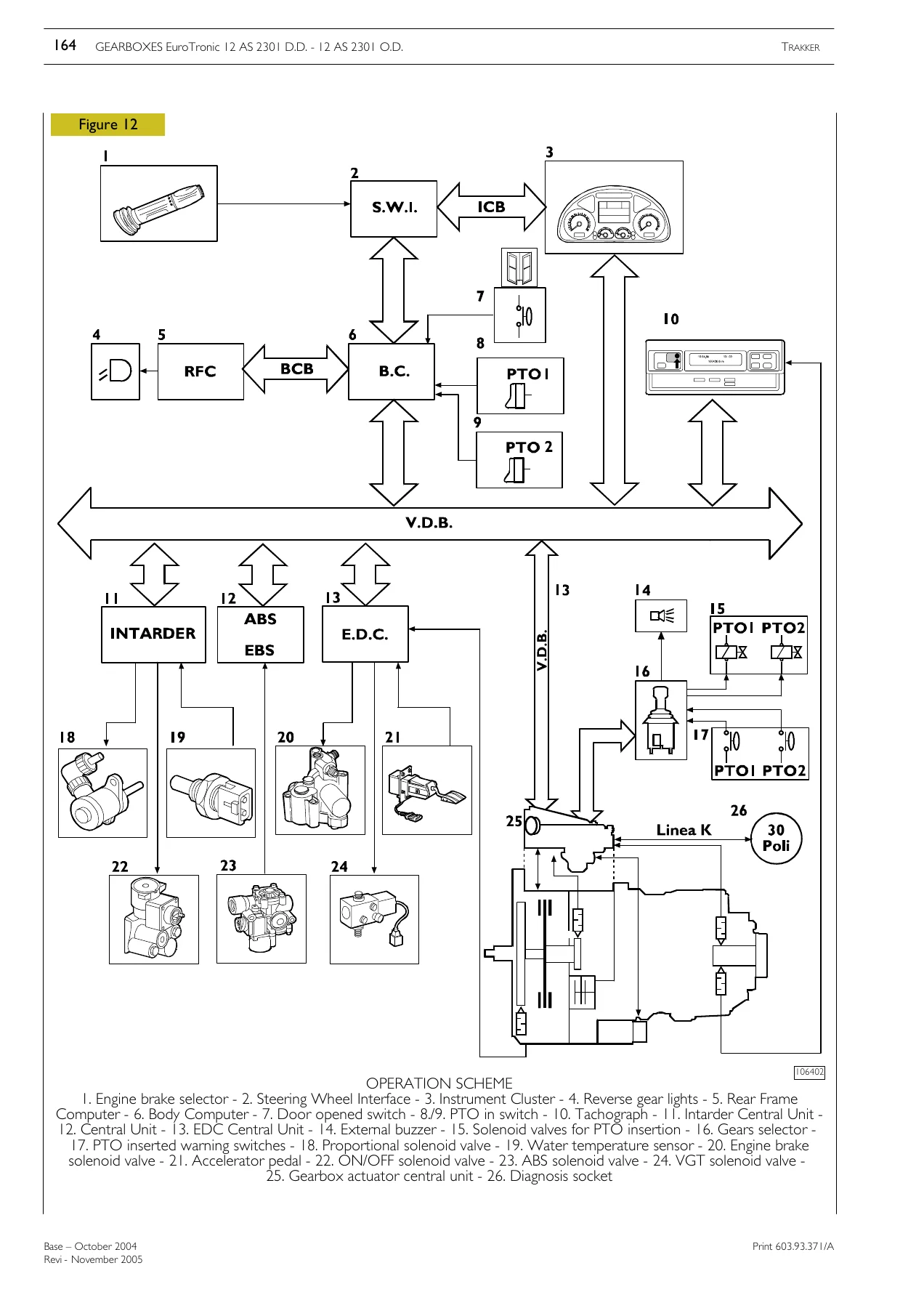
The complete Multiplex system — Body Computer, Front Frame Computer, Rear Frame Computer, Cabin Module, Driver Door Module, Passenger Door Module, Steering Wheel Interface, Bed Module, Instrument Cluster, spiral contact, VDI centre. Includes component code tables, CAN line testing procedures, the LIMP HOME function, diagnosis on cluster, automatic and manual air-conditioning, Immobilizer, EDC MS6.2 engine management, ABS-EBL, ECAS, EuroTronic and Intarder electronic systems, plus a full set of circuit charts and block charts. Component codes, pin-out tables and connector views are given for every electronic centre.
What the Iveco Trakker Repair Manual 603.93.371 Lets You Do
This is the reference that turns a Trakker job into a sequence of documented steps instead of guesswork. Whether you are pulling a cylinder head on an F3BE0681C, adjusting the pre-load on a tandem axle epicyclic reduction gear, selecting the correct main bearing shell class from the crankshaft markings, tracking down an intermittent CAN line fault on the Body Computer, rebuilding a ZF 16S221 O.D. gearbox, or setting the splitter linkage on a Meritor tandem — the procedures, the tightening torques, the rolling torque figures and the assembly clearances are all here, in the order a technician actually works in.
The value of having the Iveco Trakker repair manual at hand is not just speed, it is avoiding the expensive mistakes: a bearing shell of the wrong selection class, a synchroniser ring under the wear limit, a cap gap set out of tolerance, a phonic wheel timed one tooth out, an actuator travel that damages the variable geometry mechanism. The torque and clearance tables in this workshop manual are what keep a rebuilt Trakker component performing the way IVECO intended.
IMAGES PREVIEW
Instant PDF Delivery
The manual is delivered as a PDF immediately after payment — no shipping, no waiting, no physical book to store. Open it on a workshop laptop, a tablet, a phone or any PDF reader on the bench. Search the sections you need, zoom in on the diagrams and exploded views, and print only the pages relevant to the job in front of you. Because the whole 1,800-page manual lives in a single file, nothing is lost between sections: the F2B engine data, the ZF gearbox overhaul instructions and the Multiplex wiring charts are all reachable from one document.
Whether you are running a workshop, maintaining a fleet of Trakker trucks, or working on a single 8×8 or 6×6 unit, this Iveco Trakker 603.93.371 repair manual gives you the same depth of information the Iveco assistance network uses — at a fraction of the cost and available the moment you need it.
Reviews
There are no reviews yet.