
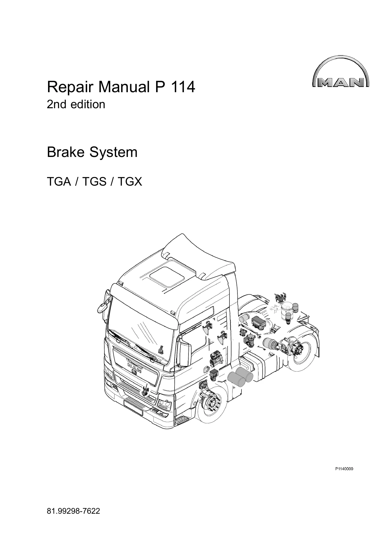
MAN TGA TGS TGX Brake System Repair Manual P114 2nd Edition – PDF Download
Original price was: $67.95.$44.95Current price is: $44.95.
The complete MAN TGA / TGS / TGX brake system repair manual, P114 2nd edition. Covers air compressor, air dryer, four-circuit protection valve, pressure control modules, relay valve, brake cylinder, ALB setting, VOSS push-in connections and full technical data. Instant PDF download.
Description
The MAN TGA / TGS / TGX Brake System Repair Manual is the complete workshop reference for the compressed-air brake system fitted to these heavy truck platforms. Published as document 81.99298-7622 under the P 114 reference and issued as the 2nd edition with a copy deadline of 11.2010, this manual covers the four-circuit compressed-air brake system to EC Directives in full. Every major brake component — from the air compressor and air dryer through to the relay valve, brake cylinder and VOSS push-in connections — is documented with removal and installation procedures, tightening torques and special tool references. The manual also includes function diagrams for 2-axle, 3-axle and 3-axle with ALB and anti-jackknife brake configurations, making it a comprehensive resource for diagnosing and repairing the brake system on TGA, TGS and TGX trucks.
File Details
- Manual type: Brake System Repair Manual
- Brand: MAN
- Models: TGA, TGS, TGX
- Document number: 81.99298-7622
- Reference: P 114
- Edition: 2nd edition
- Copy deadline: 11.2010
- Language: English
- Page count: 152
- File format: PDF
Chapters Covered
- Introduction
- Brake units
- Auxiliary consumers
- Gearbox
- VOSS Push-In System
- Technical Data
Safety Instructions and Functional Description
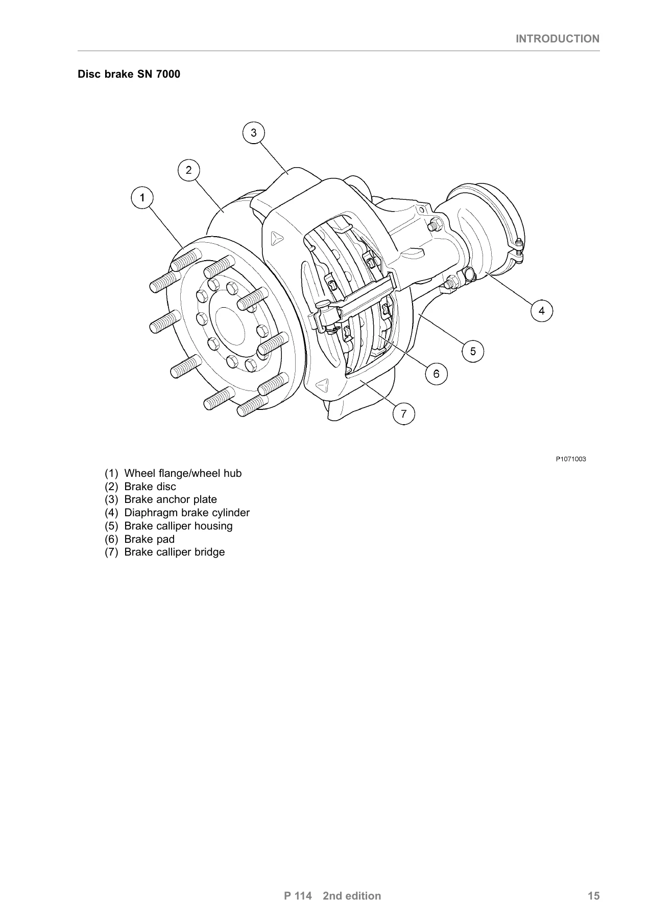
The manual opens with an extensive safety chapter covering general accident prevention, working on the brake system, compressed natural gas (CNG) systems, high-pressure lines, the vehicle electrical system, electric welding, painting, airbag and belt tensioner units, and the auxiliary heater. The functional description that follows explains the four-circuit compressed-air brake system to EC Directives, covering compressed-air supply, braking power control, pressure values, wheel brake design for front and rear axles, reservoir and brake circuits, and ALB settings. The wheel brake specifications are detailed: a disc brake with automatic adjustment, 432 mm outside disc diameter, 45 mm disc thickness when new, 172.6 mm effective friction radius, 7840 mm² brake pad area, and 30 mm brake pad thickness with backing plate when new.
Function Diagrams
A substantial section of function diagrams covers the brake system schematics for different vehicle configurations. These include 2-axle, 3-axle, and 3-axle with ALB and anti-jackknife brake layouts. Diagrams cover the service brake, parking brake, trailer control, auxiliary consumers, controlled engine brake, gearbox, and ECAS. Each diagram is accompanied by a component reference table identifying valves, cylinders, reservoirs, sensors, and control modules by their MAN item numbers and descriptions. These diagrams are essential for tracing air lines, understanding circuit division, and diagnosing faults in the brake system.
Brake Units
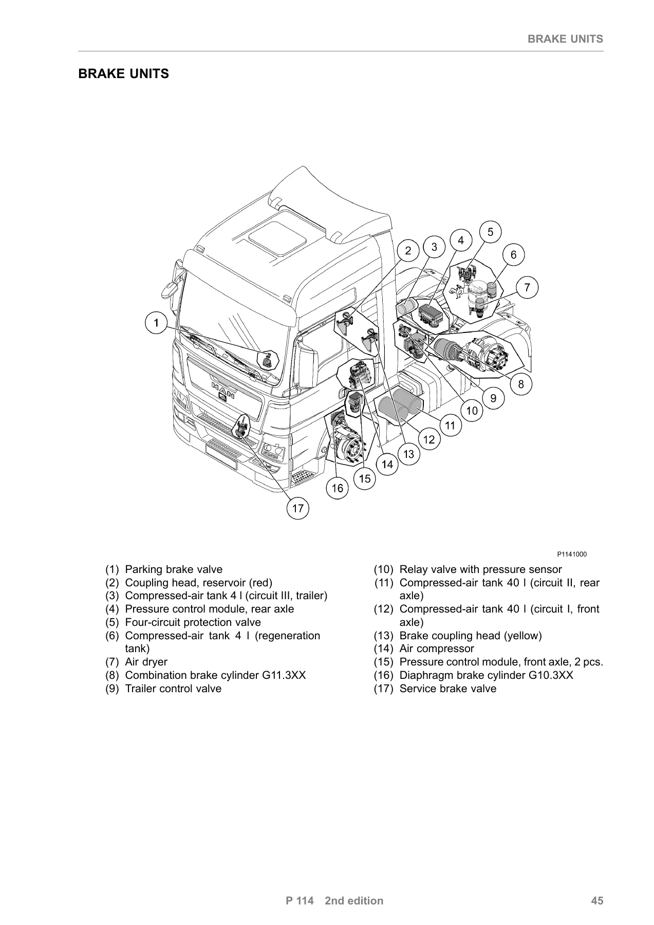
The brake units chapter is the core of the manual. It covers removal and installation procedures for every major component in the system, organised by component. The air compressor section covers both one-cylinder and two-cylinder units. The air dryer section covers single-chamber and two-chamber variants, with mounting positions in the rear of the frame, next to the battery box, or under the battery box. The four-circuit protection valve is documented in three mounting positions: under the battery box, next to the battery box, and in the rear of the frame. The pressure-limiting valve section covers the standard valve and the variant for the 4-wheel parking brake. The service brake valve, front axle and rear axle pressure control modules, parking brake valve, anti-jackknife brake valve, and the two-way valve for the 4-wheel parking brake are all covered with step-by-step procedures. The relay valve section distinguishes between drum brake and disc brake applications. The pressure sensor and position sensor (ALB) sections include installation positions, tightening torques, and — for the ALB — setting procedures using an angle measuring device or MAN-cats voltage values. The trailer control valve is covered both in its standard form and the variant for the 4-wheel parking brake. The coupling head, brake cylinder, compressed-air tank, and test connections chapters round out the brake units section with detailed removal and installation instructions.
Auxiliary Consumers
This chapter covers the PriTarder solenoid valve unit and solenoid valve, used for the controlled engine brake system, plus the ECAS solenoid valve for the electronic-controlled air suspension. Removal and installation procedures are provided for each.
Gearbox
The gearbox chapter covers removing and installing the overflow valve and non-return valve, with technical data on operating pressure and tightening torques.
VOSS Push-In System
The VOSS push-in system chapter explains how to repair line and push-in connections. It covers routing and mounting plastic pipes with safety instructions, cutting pipes to length, mounting connectors, T-pieces and connection nipples using the grips and impact tools, undoing and reinstalling push-in connections, fitting new O-rings, screwing in the union screw, and checking firm seating of the push-in connection. This section is essential for any work involving the plastic air lines that connect the brake system components.
Technical Data
The technical data section at the end of the manual consolidates the key specifications and torque values for every component covered. This includes mounting bolt torques, union screw torques for VOSS push-in connections, operating pressures, reservoir pressures, safety pressures for each circuit, and the wheel brake specifications. Having all the critical values in one section makes it straightforward to look up the correct torque or pressure when finishing a repair.
Put the MAN TGA TGS TGX Brake System Repair Manual to Work in Your Workshop
IMAGES PREVIEW
This MAN TGA TGS TGX brake system repair manual gives you the exact procedures, tightening torques, and component specifications needed to service the air brake system on these trucks correctly. Whether you are replacing an air dryer, rebuilding a brake calliper, setting the ALB linkage, or diagnosing a pressure control module fault, the manual’s step-by-step instructions and function diagrams walk you through each job in the sequence a professional technician would follow. The torque tables and technical data ensure every fastener is tightened to specification, every pressure value is set correctly, and every component is installed as MAN intended. Delivered as an instant PDF download, the manual is searchable, printable, and accessible on any device — phone, tablet, laptop or workshop PC. No shipping, no waiting. Buy once, use it for every brake job on your TGA, TGS or TGX.
Reviews
There are no reviews yet.