
JCB 3C 3CX 4CX Service Manual – Steering, Engine & Servo Control Sections PDF
Original price was: $67.95.$44.95Current price is: $44.95.
Complete PDF service manual for JCB 3C, 3CX, and 4CX machines covering steering systems, JCB DieselMax engine, and servo controls. Serial numbers 960001-989999 and 1327000-1349999.
Description
JCB 3C, 3CX, 4CX Service Manual – Steering, Engine & Servo Control Sections
This PDF service manual covers the steering system, JCB DieselMax engine, and servo control systems for JCB 3C, 3CX, and 4CX machines. It applies to machines from serial number 960001 to 989999 and 1327000 to 1349999. The manual is presented in English and covers these systems in substantial technical depth, making it suitable for professional technicians, fleet maintenance teams, and owner-operators who need accurate procedures and specifications for diagnosis, repair, and adjustment.
File Details
- Manual Type: Service Manual (Workshop Manual)
- Brand: JCB
- Models Covered: 3C, 3CX, 4CX
- Serial Number Coverage: 960001 to 989999 and 1327000 to 1349999
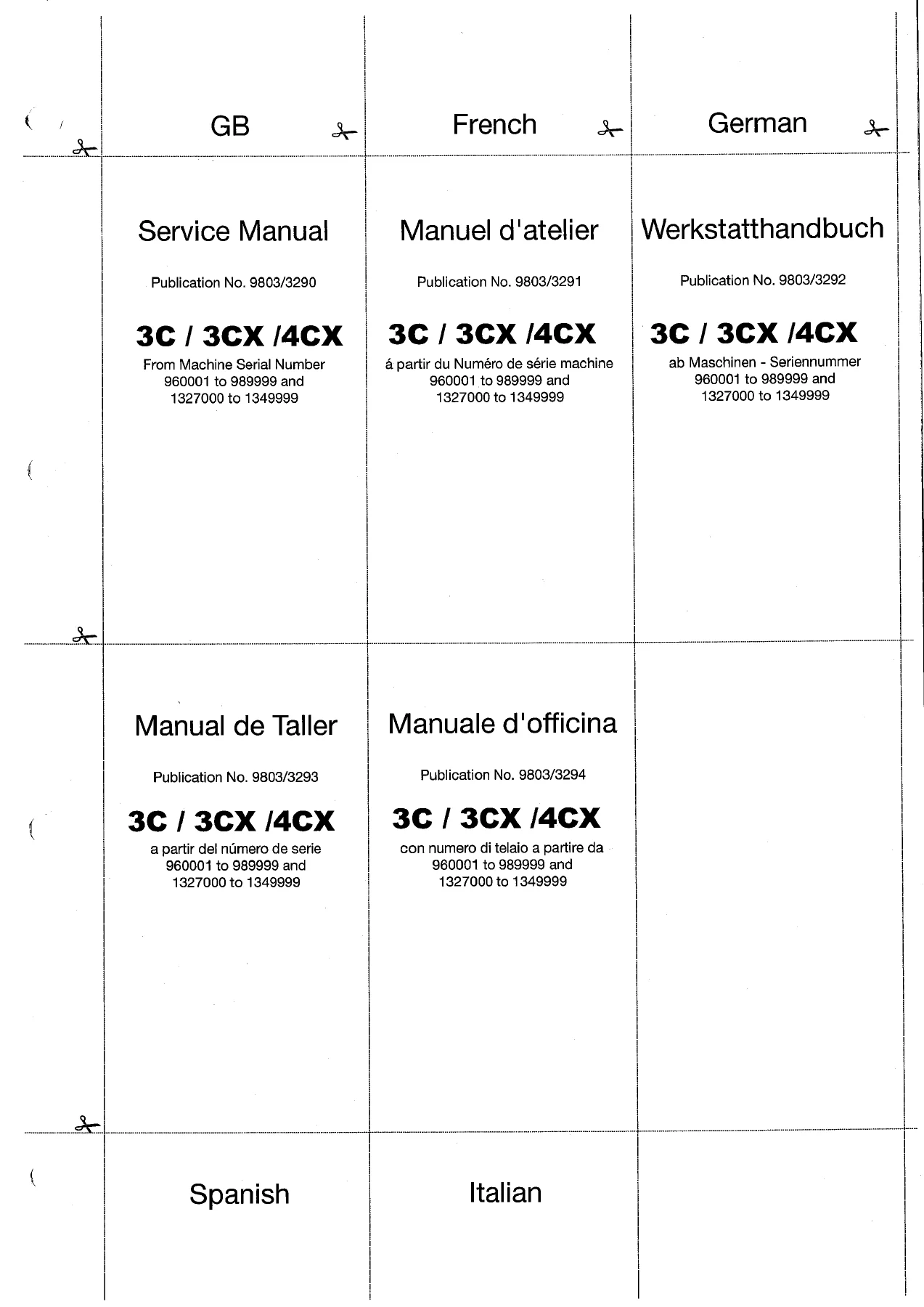
- Language: English (multilingual title page in French, German, Spanish, and Italian)
- Publication Numbers: 9803/3291, 9803/3292, 9803/3293, 9803/3294
- File Format: PDF
- Page Count: Approximately 470 pages
Chapters Covered
- Section H – Steering
- Section K – Engine (JCB DieselMax)
- Section L – Servo Controls
Section H – Steering System
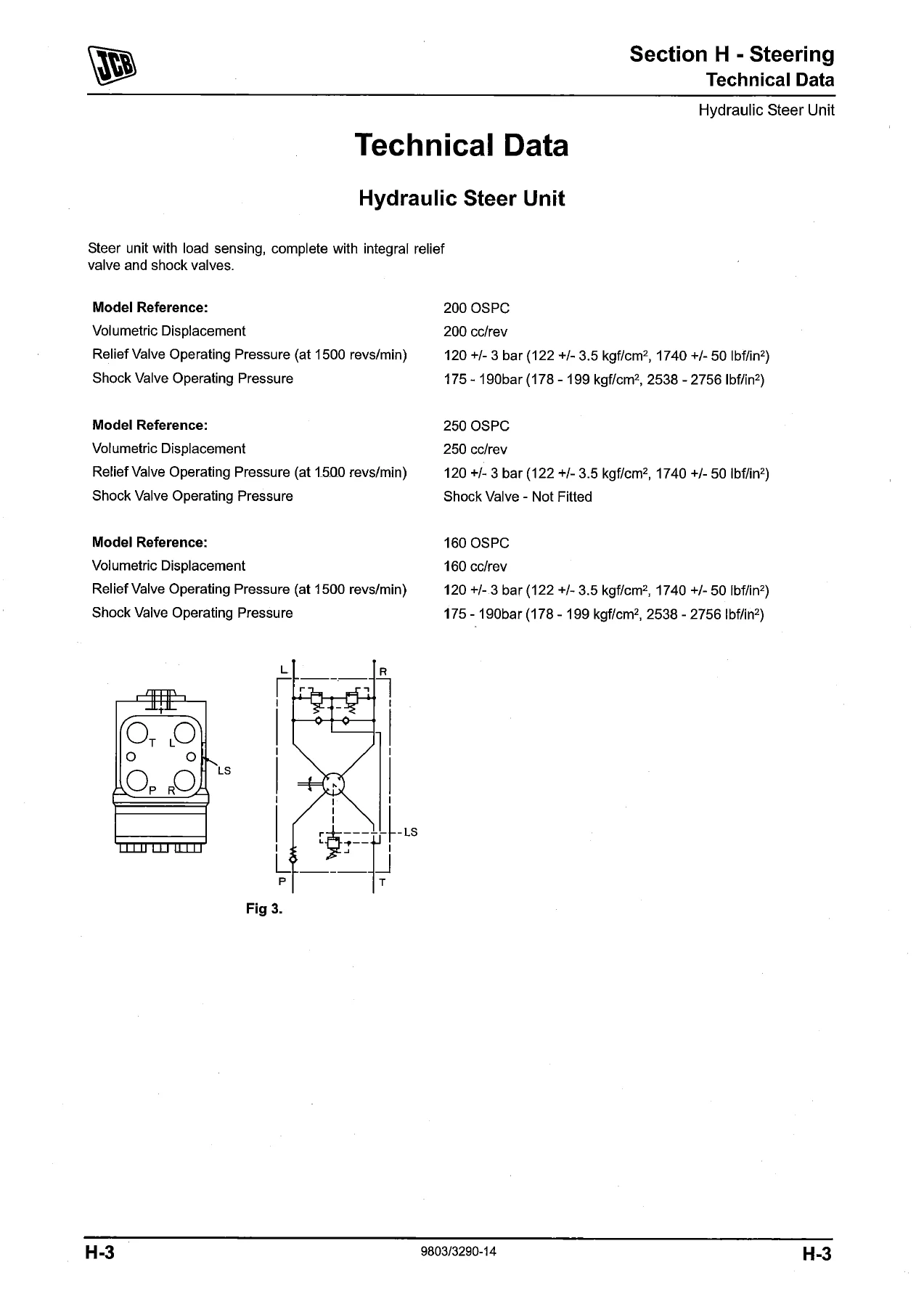
The steering section opens with a numerical list of special service tools required for the procedures in this manual, including seal fitting tools, hexagon spanners (55 mm through 125 mm A/F), and tool detail references. Technical data follows for the hydraulic steer unit, covering the 200 OSPC, 250 OSPC, and 160 OSPC models with volumetric displacement figures (200 cc/rev, 250 cc/rev, and 160 cc/rev respectively). Relief valve operating pressure is listed at 120 +/- 3 bar (122 +/- 3.5 kgf/cm², 1740 +/- 50 lbf/in²) at 1500 revs/min. Shock valve operating pressure is 175 – 190 bar (178 – 199 kgf/cm², 2538 – 2756 lbf/in²) for the 200 OSPC and 160 OSPC models, while the 250 OSPC does not have a shock valve fitted.
Basic operation is described for both 2-wheel steer and 4-wheel steer machines, with the main components identified: priority valve, load sensing steer unit, and double acting power track rod rams. The steer mode selection system is explained, covering 2-wheel steer, 4-wheel steer, and crab steer modes, including the three-position switch, control unit, steer mode control valve solenoids, indicator lights, and proximity sensors that prevent mode changes until the wheels are in the straight ahead position.
Steer circuit schematics are provided for 2-wheel steer machines and both types of 4-wheel steer machines (Steer Mode Valve Type 1 and Type 2). Component keys identify the priority valve, steer unit, shock valves, steering system relief valve, steer mode control valve, power track rod rams, pumps, hydraulic tank, and steering pressure test point. Circuit descriptions then detail steer unit operation in neutral, left turn, right turn, right turn unassisted (engine stopped), shock valve operation, and 2-wheel steer and crab steer modes. Priority valve operation is covered for both neutral and turning conditions.
The electrical system chapter covers PCB (relay) controlled steer mode and ECU controlled steer mode, with full wires and connectors information, earth points, component keys, and connector locations. Diagnostic blink codes are provided for applicable machines from serial number 1327630, with fault descriptions and actions for 1, 2, and 3 flash codes.
Fault finding tables address five major fault categories: steering wheel difficult to turn, steering wheel turns on its own, machine will not turn when the steering wheel is turned, steering fails to respond to selected mode (4WS machines only), and steering fails to phase accurately or drifts out of phase during operation (4WS machines only). Each table lists probable causes and recommended actions.
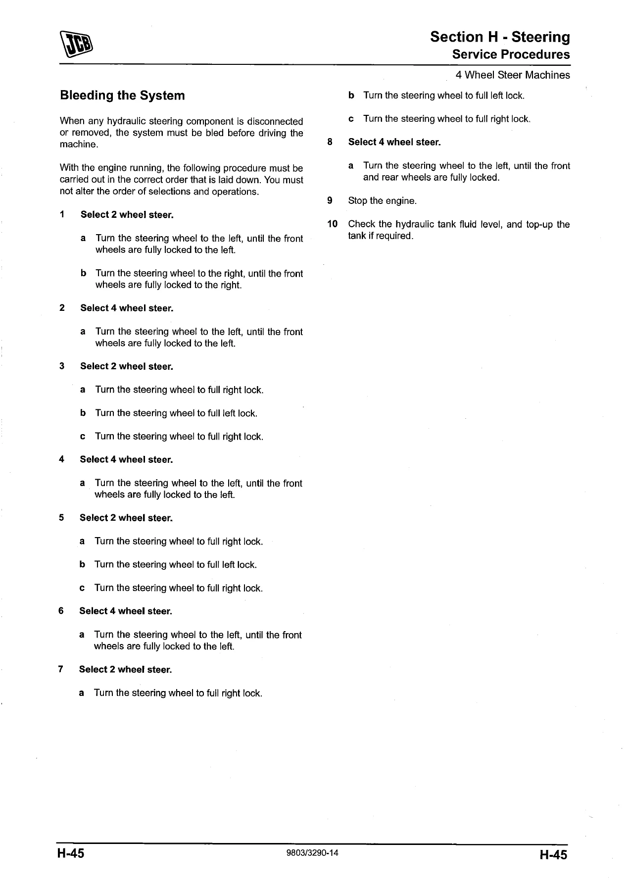
Service procedures include hydraulic pressure tests (standby pressure and steering pressure), steer priority valve cleaning, bleeding the system for both 2-wheel and 4-wheel steer machines, re-phasing the road wheels, proximity switch setting, steer mode valve solenoid operation checking, and checking components for internal hydraulic leakage. Detailed removal and replacement procedures are provided for the priority valve (including dismantle and assemble with torque settings), power track rod, link arms (with wheel alignment check), rams (dismantle and assemble with torque settings), steer mode valve Type 1 and Type 2 (removal, replacement, dismantle, and assemble), and the hydraulic steer unit (removal, replacement, and full dismantle and assemble procedures).
Section K – JCB DieselMax Engine
The engine section begins with a numerical list of special service tools, including engine lifting brackets (892/01160) and spanners for the viscous cooling fan (825/10035 and 825/10036). Technical data covers the JCB DieselMax engine in its various configurations: SA (naturally aspirated, 63 kW / 84 bhp), SB (turbocharged, 68 kW / 92 bhp and 74 kW / 100 bhp), SD (turbocharged, 63 kW / 84 bhp and 68 kW / 92 bhp), and SF (turbocharged and intercooled, 74 kW / 100 bhp). All variants are 4-cylinder, in-line, 4-stroke engines with a nominal bore of 103 mm (4.05 in), stroke of 132 mm (5.196 in), and displacement of 4.4 litres (268.5 in³). Firing order is 1, 3, 4, 2 with number 1 cylinder at the crankshaft pulley end. Compression ratios are 18.6:1 for SA, 18.3:1 for SB, and 17.2:1 for SD and SF. Valve tip clearances (measured cold) are 0.19-0.27 mm inlet and 0.56-0.64 mm exhaust for SA/SB, and 0.35 mm inlet and 0.56-0.64 mm exhaust for SD/SF. Lubricating oil pressure is 4.0 to 4.8 bar (58 to 70 lb/in²). Idle speed is 910 r.p.m., maximum governed speed is 2200 r.p.m., and high idle speed is 2350 r.p.m.
Cold start heater electrical connections are explained with a schematic diagram and component key, covering the grid heater, battery, starter switch, warning light, primary fuse, electronic control unit (ECU), ambient air temperature sensor, and relay. Diagnostic blink codes for the cold start heater system are provided with 1 to 4 flash codes covering temperature sensor open circuit, temperature sensor short circuit, heater relay fault, and heater relay output fault.
Wires and connectors for the cold start heater are documented with component keys, connector lists, and harness information. Electrical sensor and solenoid removal and replacement procedures cover engine cold start switch, engine oil pressure switch, coolant temperature sender unit, cold start advance solenoid, and engine shut-off solenoid (ESOS).
Engine bay support frame removal and replacement is described step by step, including disconnecting the engine cover release cable, air intake hoses, water pipes, brake fluid reservoir, coolant hoses, fuel lines, and electrical harness before lifting the support frame clear. Cooling fan viscous coupling operation is explained with the temperature-sensitive bi-metal coil, showing how the coupling acts as a variable clutch with maximum slippage below 40°C and minimum slippage at approximately 65°C. Removal and replacement procedures are provided with special spanner usage and left-hand thread note. Cooling radiator removal and replacement covers oil cooler matrix, air conditioning condenser, radiator hoses, fan cowl, support frame bracket, charge air cooler (CAC) on turbocharged engines, and radiator mounting bolts. Coolant expansion tank removal and replacement, low coolant level sensor servicing (not fitted on machines from serial no. 976832), and fuel injection pump removal and replacement procedures are also included.
The JCB DieselMax engine removal and replacement section provides component identification with a detailed illustration and component key covering lifting brackets, electrical connections, fuel line connectors, vacuum hose connectors, fixing bolts, drive shaft fixings, exhaust components, engine mounting bolts, and gearbox mounting bolts. Torque settings are provided for the various fixings. The removal procedure covers disconnecting the battery, removing the engine bay support frame, engine cover, front grille housing, cooling pack, exhaust stack and silencer, heater hose, brake vacuum hose, throttle cable, fuel line, and all electrical ancillary devices. The gearbox and torque converter are separated, lifting brackets fitted, and the engine lifted clear. Replacement notes cover torque converter location, flexi-plate to flywheel bolts, radiator sub-assembly fitting, brake vacuum hose reconnection, coolant hose location stops, and fluid filling procedures.
Section L – Servo Controls
The servo controls section opens with an introduction to the machine types covered: Precision Control (fixed flow double gearpump, sectional loader valve with two manual and one servo operated closed-centre spools, sectional excavator valve with seven servo operated closed-centre spools, hydraulic load sense and pressure compensator circuit, separate Inloader valve), Advanced EasyControl (formerly Advanced Precision Control – variable flow pump, sectional loader valve with three servo operated closed-centre spools, sectional excavator valve with seven servo operated closed-centre spools, hydraulic load sense and pressure compensator circuit), and EasyControl (fixed flow double gearpump, monoblock loader valve with two manual and one servo operated open-centre spools, monoblock excavator valve with six servo operated open-centre spools, integrated Unloader valve, separate servo operated auxiliary valve block).
Service tools are listed with numerical references, including a test relay with LED indicator (716/30313), pilot hose release tool for quick-connect hose fittings (825/10053), and digital pressure test set (998/11051). Fuses and relays are documented for Precision Control, Advanced EasyControl, and EasyControl machines, with fuse and relay identification for both early and later machines, including changes from May 2009 and from serial no. 1347278.
Schematic circuits are provided for electrics on Precision Control machines (clam shovel/extending dipper with manual isolator switch and isolator relay), Advanced EasyControl machines (to May 2009 with analog instruments, and from May 2009 with digital instruments), and EasyControl machines (to May 2009 and from May 2009). Hydraulic schematics are included for Precision Control machines, Advanced EasyControl machines (including Variflow pump internal circuit), and EasyControl machines.
The Precision Control System section covers excavator servo controls, load sense and pressure compensator function, Inloader valve and hydraulic speed control (HSC) function, grading mode, auxiliary service thumbwheel controls, and joystick enable and seat interlock switches. Hydraulic operation and schematics are provided for the unloader valve variant. Electrical operation and schematics cover the joysticks enable circuit, hydraulic speed control (HSC) Inloader override circuit, and clam shovel and extending dipper circuit. Fault finding tables and thumbwheel diagnostic blink codes are included. Service procedures cover checking servo pressure, main system pressures, internal leakage in the load sense line, Inloader valve testing, pressure compensator network testing, and bleeding the auxiliary service pilot hose.
The Advanced EasyControl System section follows a similar structure, covering loader and excavator servo controls, Variflow pump, load sense and pressure compensator function, auxiliary service thumbwheel controls, joystick enable and seat interlock switches, hydraulic operation and schematics, electrical operation and schematics (joysticks enable circuit, excavator/loader changeover circuit, excavator/loader auxiliary service controls), fault finding tables, thumbwheel diagnostic blink codes, and service procedures (checking servo pressure, main system pressures, hydraulic services cycle times, internal leakage in the load sense line, pressure compensator network testing, and quick-connect pilot hoses).
The EasyControl System section covers excavator servo controls, unloader and hydraulic speed control (HSC) function, auxiliary service thumbwheel controls, joystick enable and seat interlock switches, excavator bucket thumb ram (if fitted), hydraulic operation and schematics, electrical operation and schematics (joysticks enable circuit, hydraulic speed control, excavator/loader auxiliary changeover circuit, excavator/loader auxiliary service controls), fault finding tables, thumbwheel diagnostic blink codes, and service procedures (checking servo pressure, main system pressure, quick-connect pilot hoses).
Component sections include joystick and stabiliser controls (joystick controllers, stabiliser controls, ISO and SAE control pattern changeover valve, joystick/auxiliary control changeover valve, removal and replacement, dismantle and assemble), loader lever controls (dismantle and assemble), servo pressure supply valve (proportional solenoid valves operation, PWM controller electronic control unit, removal and replacement), Inloader valve (specifications, descriptions, pump P2 directed to tank, pump P2 in circuit, Inloader operation override, graph of system pressures, removal and replacement), hydraulic pump gearpumps (specifications, descriptions, removal and replacement, dismantle and assemble), hydraulic pump Variflow (specifications, descriptions, removal and replacement, dismantle and assemble), loader valve sectional type (specifications, descriptions, loader valve services, pressure compensator valves operation, dismantle and assemble, valve block sections, servo operated spool, manually operated electric detent spool, manually operated mechanical detent spool, load sense relief valve, external and internal auxiliary relief valves, flow regulator valve, pressure compensator valves, load hold check valves), loader valve monoblock type (specifications, descriptions, loader valve services, unloader operation, removal and replacement, dismantle and assemble), excavator valve sectional type (specifications, descriptions, excavator valve services, pressure compensator valves operation, removal and replacement, dismantle and assemble, valve block sections, servo operated spool, external and internal auxiliary relief valves, pressure compensator valves, load hold check valves), excavator valve monoblock type (specifications, descriptions, excavator valve services, Hydraulcamps operation, removal and replacement, dismantle and assemble), auxiliary valve block sectional type (specifications, descriptions), auxiliary valve block monoblock type (specifications, descriptions), and cab seat (service procedures, seat position sensors adjustment, removal and replacement).
Key Technical Specifications Featured
- Hydraulic Steer Unit Relief Valve Pressure: 120 +/- 3 bar (122 +/- 3.5 kgf/cm², 1740 +/- 50 lbf/in²) at 1500 revs/min
- Hydraulic Steer Unit Shock Valve Pressure: 175 – 190 bar (178 – 199 kgf/cm², 2538 – 2756 lbf/in²)
- Standby Pressure: 5.9 to 8.7 bar (86 to 126 lbf/in²)
- Steering Pressure Test Point: Located on pump body (X)
- JCB DieselMax Engine Configuration: 4-cylinder, in-line, 4-stroke
- Nominal Bore: 103 mm (4.05 in)
- Stroke: 132 mm (5.196 in)
- Displacement: 4.4 litres (268.5 in³)
- Firing Order: 1, 3, 4, 2 (No. 1 cylinder at crankshaft pulley end)
- Compression Ratio: SA 18.6:1, SB 18.3:1, SD/SF 17.2:1
- Lubricating Oil Pressure: 4.0 to 4.8 bar (58 to 70 lb/in²)
- Idle Speed: 910 r.p.m.
- Maximum Governed Speed: 2200 r.p.m.
- High Idle Speed (Throttle Stop): 2350 r.p.m.
Why This Manual Matters for JCB 3C, 3CX & 4CX Owners
Steering and servo control systems on JCB 3C, 3CX, and 4CX machines are complex hydraulic and electrical networks. Getting a diagnosis wrong or using incorrect pressures and torque values can lead to premature component failure, poor steering response, or unsafe machine operation. This service manual provides the exact specifications, step-by-step procedures, and diagnostic tables needed to carry out repairs correctly the first time. Whether you are troubleshooting a steering fault, rebuilding a power track rod ram, servicing the priority valve, or diagnosing a servo control electrical issue, the relevant data is here.
The manual covers both early and later machine variants, including PCB-controlled and ECU-controlled steer modes, Type 1 and Type 2 steer mode valves, and the different servo control systems (Precision Control, Advanced EasyControl, and EasyControl). The fault finding tables and diagnostic blink codes help narrow down problems efficiently, while the detailed dismantle and assemble procedures with torque settings ensure components are rebuilt to specification.
IMAGES PREVIEW
Instant PDF Delivery – No Shipping, No Waiting
This JCB 3C, 3CX, 4CX service manual is delivered as a PDF download immediately after purchase. There is no physical book to ship, no waiting for delivery, and no risk of a damaged or lost parcel. The PDF can be viewed on any device – laptop, desktop, tablet, or smartphone – and pages can be printed for use in the workshop. Keep it on your computer, load it onto a USB stick, or print the sections you need for the job at hand.
Whether you are a professional technician, a fleet maintenance manager, or an owner-operator who prefers to carry out their own repairs, this service manual gives you the technical information needed to maintain and repair JCB 3C, 3CX, and 4CX machines accurately and safely. Download your copy today and have the workshop manual at your fingertips.

Reviews
There are no reviews yet.