
JCB JS Auto Range Tracked Excavators – Section C Electrics Service Manual
Original price was: $34.95.$19.95Current price is: $19.95.
Complete JCB JS Auto Range tracked excavator electrical service manual. Covers the AMS, ECU1, EMS, fault finding and full harness data for JS115, JS130, JS145, JS160, JS180, JS200, JS210 and JS220 machines.
Description
The JCB JS Auto Range Tracked Excavators – Section C Electrics Service Manual is the complete electrical section of the JCB service documentation for the JS family of tracked excavators. This manual covers the Advanced Management System (AMS), every electrical function fitted to the JS machine, diagnostic procedures with and without the JCB Servicemaster tool, and the full wiring harness data set for the JS115, JS130, JS145, JS160, JS180, JS200, JS210 and JS220 tracked excavators. Every circuit description, solenoid output, pressure switch input, EMS message and harness pin-out needed to service the machine electrics is gathered in one document.
File Details
- Manual type: Service manual – Section C Electrics
- Brand: JCB
- Models covered: JS115, JS130, JS145, JS160, JS180, JS200, JS210, JS220 tracked excavators (Auto Range)
- Document number: 9813/1000
- Language: English
- File format: PDF
- Page count: 225 pages
Chapters Covered
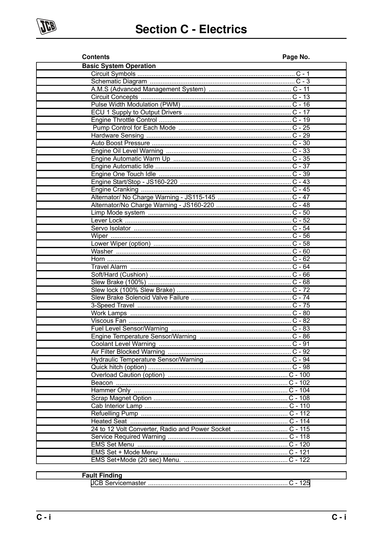
- Circuit Symbols
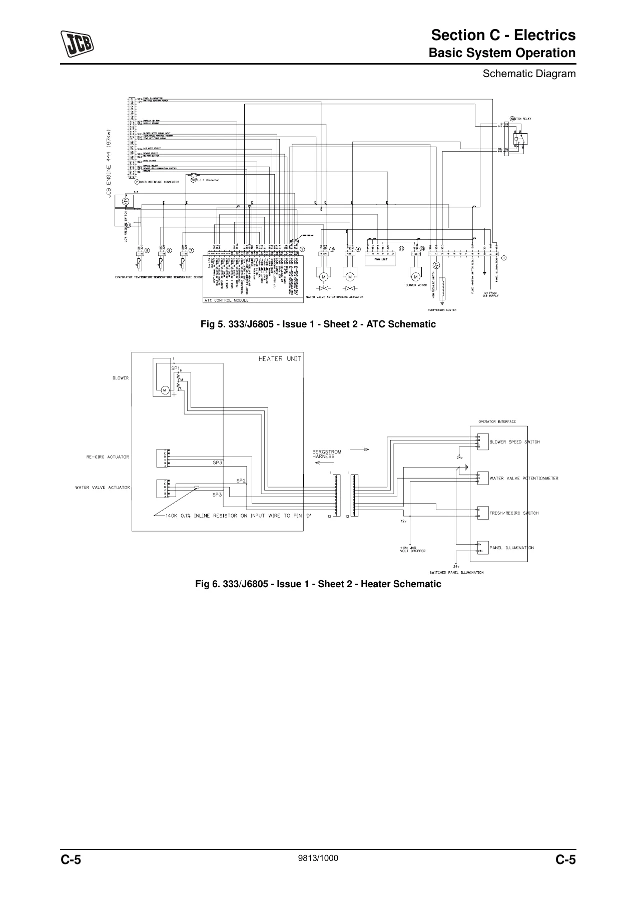
- Schematic Diagram
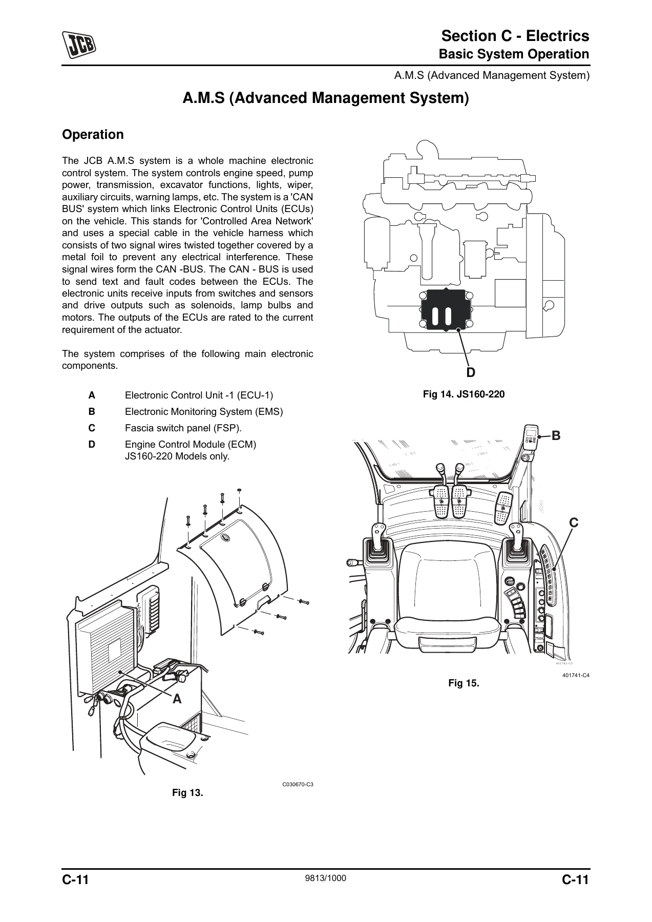
- A.M.S (Advanced Management System)
- Circuit Concepts – digital and analogue inputs, low/high side and modulated outputs
- Pulse Width Modulation (PWM)
- ECU 1 Supply to Output Drivers
- Engine Throttle Control (JS115-145 and JS160-220)
- Pump Control for Each Mode
- Hardware Sensing
- Auto Boost Pressure
- Engine Oil Level Warning
- Engine Automatic Warm Up
- Engine Automatic Idle
- Engine One Touch Idle
- Engine Start/Stop – JS160-220
- Engine Cranking
- Alternator / No Charge Warning (JS115-145 and JS160-220)
- Limp Mode system
- Lever Lock
- Servo Isolator
- Wiper, Lower Wiper (option) and Washer
- Horn
- Travel Alarm
- Soft/Hard (Cushion)
- Slew Brake (100%)
- Slew lock (100% Slew Brake)
- Slew Brake Solenoid Valve Failure
- 3-Speed Travel
- Work Lamps
- Viscous Fan
- Fuel Level Sensor / Warning
- Engine Temperature Sensor / Warning
- Coolant Level Warning
- Air Filter Blocked Warning
- Hydraulic Temperature Sensor / Warning
- Quick hitch (option)
- Overload Caution (option)
- Beacon
- Hammer Only
- Scrap Magnet Option
- Cab Interior Lamp
- Refuelling Pump
- Heated Seat
- 24 to 12 Volt Converter, Radio and Power Socket
- Service Required Warning
- EMS Set Menu
- EMS Set + Mode Menu
- EMS Set+Mode (20 sec) Menu
- Fault Finding – JCB Servicemaster
- Fault Finding Without Using the JCB Servicemaster Diagnostic Tool
- Service Procedure Testing of ECU Inputs + Outputs
- Using a Multimeter
- Battery
- Wiring Harness Repair
- Harness Interconnection
- Main Harness JS115-145
- Main Harness JS160-JS180
- Main Harness JS200-JS220
- Fascia Link Harness
- Cab Harness JS115-145
- Engine Harness JS115-145
- Cab Harness JS160-JS220 (Includes Engine Harness)
Section C is the electrical heart of the JCB JS service manual. It explains how the AMS network links ECU1, the Electronic Monitoring System, the Fascia Switch Panel and – on JS160-220 models – the Engine Control Module over the CAN bus, then breaks down every input, output and PWM-controlled solenoid on the machine. Each system is documented with the circuit symbol convention, signal logic, operating description, and the specific ECU connector letter and pin number called out for testing.
What the AMS and Circuit Coverage Gives You
Because JCB uses one shared electronic architecture across the JS Auto Range, this section is what lets you work on any of the tracked models without guessing at the wiring. The digital and analogue input descriptions, low side and high side output circuits, and the PWM explanation together provide the framework for interpreting every subsequent circuit in the book. Engine throttle control, mode selection (Auto, Economy, Precision, Lifting), auto warm-up, auto idle, one-touch idle and auto boost are each broken out with the exact pressure switch, dial, CAN message or temperature threshold that triggers them.
The pump control section documents the different milliamps targets per working mode, the dynamic control factor (DCF) that adjusts pump output for barometric pressure, fuel temperature, air intake temperature, air conditioning and machine temperatures, and the mode-selection logic diagrams that decide which mA setting applies.
Diagnostics With and Without Servicemaster
The fault finding half of the manual is deliberately split so a technician can work with or without the JCB Servicemaster diagnostic tool. The no-tool section covers permanent battery supply and ignition supply test points, ground test locations, CAN-bus network continuity tests between the EMS and ECU1, diagnostic connector resistance checks, and unit-resistance checks on the EMS and ECU1 themselves – enough to confirm or eliminate an ECU1, EMS or FSP fault before replacing parts. The Servicemaster section then documents the full dealer-tool workflow: vehicle setup, diagnostics, service history, data logging, flashloader, HP Setup vehicle profile, DLA port configuration, and DLA trouble shooting.
Electrical fault text messages displayed on the EMS are catalogued with their error codes – open circuits in the 100 series, short circuits in the 200 series, CAN communication faults in the 300 series – so the message shown on the display can be matched straight to the circuit and output number on the harness diagram.
Harness Data and Wiring Diagrams
The harness data section contains the harness interconnection diagram and every machine harness layout at pin level: main harness JS115-145, main harness JS160-JS180, main harness JS200-JS220, fascia link harness, cab harness JS115-145, engine harness JS115-145, and the combined cab plus engine harness for JS160-JS220. Connector identification tables, splice locations, wire colours, cable sizes and insulation node data are all included, which makes tracing a broken wire, repinning a connector or adding an auxiliary circuit to the correct splice a straightforward job rather than a workshop guess.
Additional Coverage and Options
Optional and attachment systems are not left out. The quick hitch, overload caution, beacon, hammer only, scrap magnet, refuelling pump, heated seat, 24 to 12 volt converter, radio, power socket and viscous fan all have dedicated circuit descriptions with the ECU output or input that drives them. The EMS Set menu, Set + Mode menu and the 20-second Set + Mode menu are documented with the exact button sequence and dealer-code procedure needed to cancel service warnings, override solenoids, calibrate the throttle and configure the machine after an ECU or EMS change.
Why This Section Belongs in the Workshop
Electrical faults on a JS Auto Range excavator very rarely come down to a failed component alone – they come down to knowing which input the ECU is looking for, which output it should be driving, and at what voltage or resistance the circuit is considered healthy. That is exactly what Section C provides. Replacing an ECU1, an EMS or a throttle actuator without setting up the machine and calibrating the throttle afterwards will leave previously active options dead and the throttle system out of range. This manual documents the setup steps that must be performed when those components are changed.
Every description, table and diagram in this PDF comes straight from the JCB service documentation for the JS Auto Range tracked excavators. Whether you are diagnosing a no-charge warning, chasing a CAN-bus fault, tracing a short in a work lamp circuit, repinning a harness connector, or replacing the throttle solenoid, the correct input, output, pin and voltage reference is on the page.
IMAGES PREVIEW
Instant PDF Delivery
Delivery is instant. The JCB JS Auto Range Tracked Excavators Section C Electrics service manual is supplied as a downloadable PDF – no shipping, no waiting. Read it on a laptop, tablet or phone in the workshop, or print the pages you need for the job in front of you. Because it is a PDF, every page, table and harness diagram can be printed at full size and taken to the machine. The same document that a JCB technician uses to set up, diagnose and repair the electrical system of the JS Auto Range is now in your hands the moment payment clears.




Reviews
There are no reviews yet.