
JLG 15/20MVL 15/20MSP Operation and Safety Manual PDF – Aerial Lift Operator Manual Download
Original price was: $44.95.$27.95Current price is: $27.95.
Complete JLG Operation and Safety Manual for the 15MVL, 20MVL, 15MSP and 20MSP electric mast lifts – safety precautions, daily walk-around inspection, ground and platform control station operation, battery charging and fault codes, platform configurations, emergency procedures, specifications and operator maintenance. 108-page PDF, instant download.
Description
JLG 15/20MVL and 15/20MSP Operation and Safety Manual
Written as the Original Instructions for these machines, this JLG 15/20MVL 15/20MSP Operation and Safety Manual covers the 15MVL, 20MVL, 15MSP and 20MSP electric self-propelled mast lifts from first power-up through to parking and charging at the end of the shift. It is the document intended to stay with the machine at all times, and it is the reference an operator, supervisor or shop technician reaches for when a lift has to be inspected, started, driven, elevated, lowered, recovered from a fault or prepared for transport. Everything the manufacturer published for these models – safety warnings, control functions, operating limits, inspection routines, fault indications and operator-level maintenance data – is contained in the six sections reproduced in this file.
The manual applies to ANSI and CE specification machines, and it distinguishes between the two where the rules differ, for example in the fall protection requirements for the stockpicker platform and in the platform capacity tables.
File Details
- Manual type: Operation and Safety Manual (Original Instructions)
- Brand: JLG
- Models covered: 15MVL, 20MVL, 15MSP, 20MSP
- Language: English
- Page count: 108
- File format: PDF
- Document number: 3121230
- Specifications covered: ANSI, CE
Chapters Covered
- Section 1 – Safety Precautions
- Section 2 – Preparation and Inspection
- Section 3 – Machine Controls, Indicators and Operation
- Section 4 – Emergency Procedures
- Section 5 – General Specifications and Operator Maintenance
- Section 6 – Inspection and Repair Log
Section 1 – Safety Precautions
Opens with the safety alert symbol system and the four hazard classifications used throughout the book – DANGER, WARNING, CAUTION and NOTICE – so the reader understands exactly how serious each message is. From there the section works through operator training and knowledge requirements, workplace inspection obligations, and machine inspection before use. It then breaks the major hazards of aerial platform work into dedicated blocks: trip and fall, electrocution, tipping, and crushing and collision. The electrocution block includes the Minimum Approach Distances table, running from 10 ft (3 m) for lines up to 50 KV through to 45 ft (14 m) for lines over 750 KV up to 1000 KV. The tipping block covers sideslope and grade limits, surface capacity checks, load distribution and the rule against using the machine as a crane. The section closes with towing, lifting and hauling restrictions.
Section 2 – Preparation and Inspection
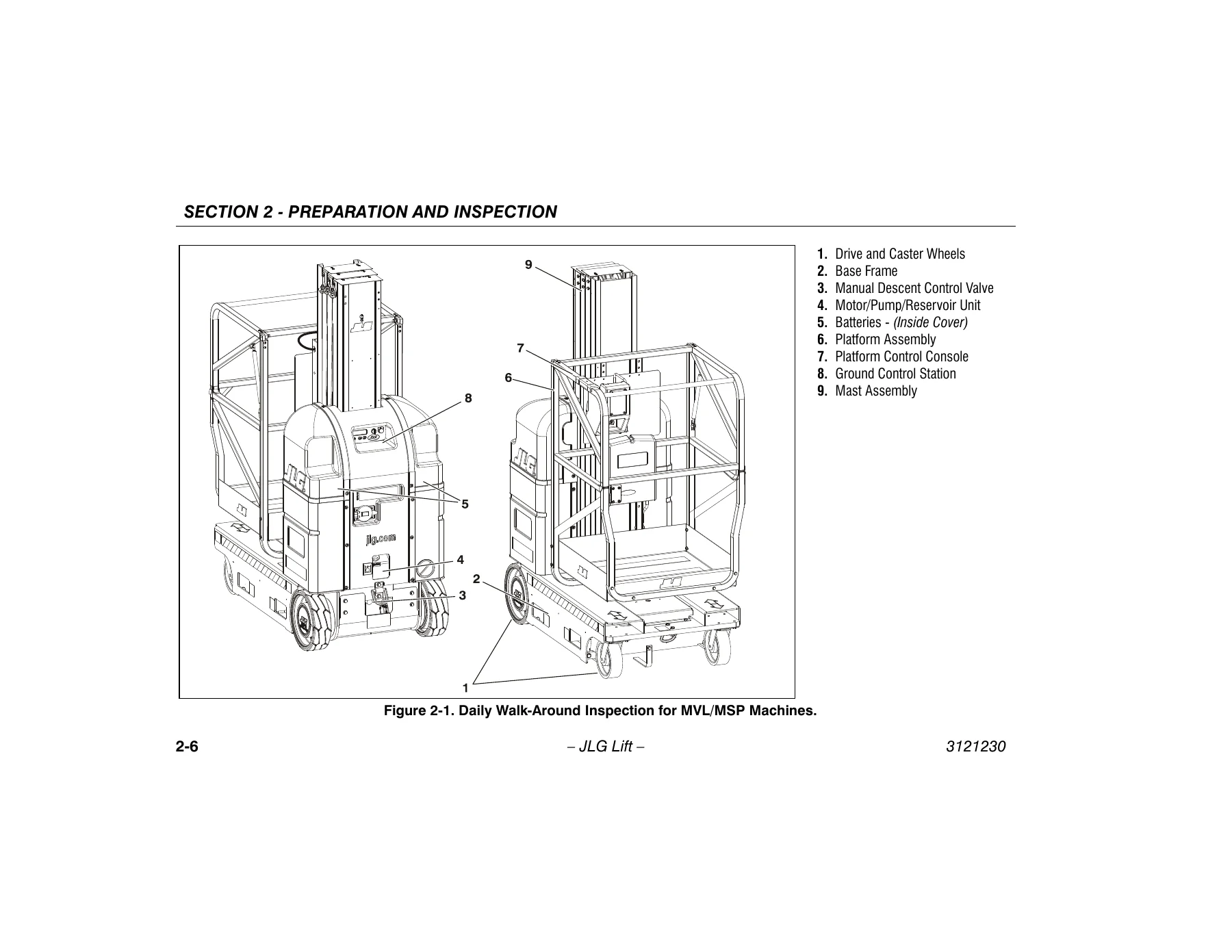
This is the inspection backbone of the manual. It sets out who may operate the machine, how training is supervised, and the operator’s authority to shut the machine down. The Inspection and Maintenance Table then defines each inspection tier – Pre-Start, Pre-Delivery, Frequent (3 months or 150 hours), Annual (no later than 13 months from the previous inspection) and Preventative Maintenance – together with the responsible party and the service qualification required. A seven-point pre-start inspection covers cleanliness and leaks, decals and placards, the storage container for the manuals, the daily walk-around, battery charge, hydraulic oil level and the function check. The nine-point daily walk-around walks the reader around the machine in sequence: drive and caster wheels, base frame and pot-hole protection components, manual descent control valve, motor/pump/reservoir unit, batteries, platform assembly and gate, platform control console, ground control station and mast assembly, including chains, sequencing cables, sheaves and slide pads. The section finishes with a step-by-step function check performed first from the ground controls and then from the platform console, covering lift up and down, pot-hole protection engagement, brake hold on a grade, tilt warning, drive speed cut-back and the joystick enable trigger.
Section 3 – Machine Controls, Indicators and Operation
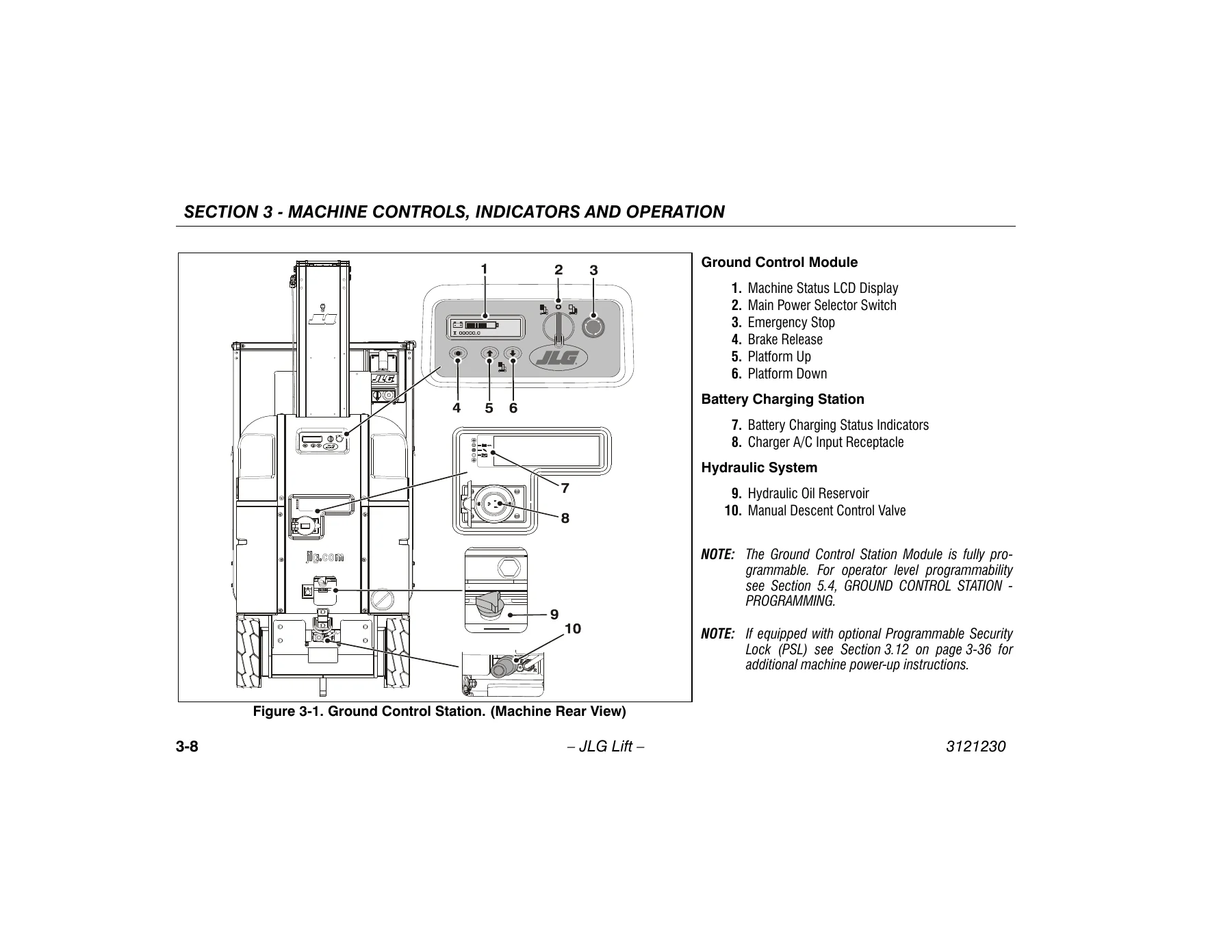
The largest chapter, and the one most operators will use daily. It describes the machines as electric self-propelled lifts with an aerial work platform mounted on an elevating aluminium mast, then explains the power-up conditions required before the machine will respond from either control station. Battery charging gets detailed treatment: the automatic charger, the three low-voltage warning levels and the action required at each, the charging status indicator LEDs, and the six flash codes the charger reports for battery voltage high, battery voltage low, charge timeout, check battery, over-temperature and QuikQ faults. The Ground Control Station is documented control by control – main power selector switch, emergency stop, brake release, platform up and down, manual descent control valve and the machine status LCD display, including its symbols and the LCD operation fault conditions table covering tilt, drive motor brush wear warning, traction module over temperature, ground control module over temperature, pump motor over current, pot-hole protection bars, platform gate and enable switch conditions. The Platform Control Console section covers the On/Off key switch, emergency stop, display panel LEDs, drive/lift mode selector, horn, joystick function enable lever, the multifunction joystick in both drive and lift mode, and the turtle/rabbit drive speed setting controls. Platform configurations are illustrated and tabulated for the front gull-wing entry, front slide bar entry, side entry with folding material tray, extendible and stockpicker platforms, with capacities listed per model. Later sub-sections handle fall protection and lanyard attachment points, quick-change platform removal and installation, transporting, lifting and tie-down procedures with the crane hook and forklift pocket locations, the optional Programmable Security Lock, the Obstruction Sensing System, the Rug Carrier accessory and the Stock-Picker Hanger accessory.
Section 4 – Emergency Procedures
Short but critical. It covers what to do when the platform operator is pinned, trapped or otherwise unable to control the machine, when the platform is caught in overhead structures, and the requirement to notify JLG Industries of any incident involving the product. It also states the post-incident inspection sequence – test from the ground control station first, then from the platform console, and do not elevate until all damage is repaired and every control is confirmed working.
Section 5 – General Specifications and Operator Maintenance
Holds the published machine data and the maintenance tasks an operator is expected to perform. Machine specifications list gross weight, stowed height, tilt indicator setting, maximum travel grade and side slope, drive speed range, base dimensions, maximum wind speed and maximum horizontal manual side force, followed by hydraulic system pressures and capacities, wheel loads and PSI per wheel for each platform type, electrical specifications, battery and charger ratings, platform data and component weights. Operator maintenance covers the AGM (VRLA) batteries, tire wear and wheel replacement, wheel lug nut tightening sequence and the three-stage torque chart, the lubrication specifications and intervals table, and the location of the lubrication points. The chapter also documents the ground control station programming mode with its Level-3 operator password and the programmable settings table, plus the drive motor brush wear warning indication and its 25-hour drive countdown.
Section 6 – Inspection and Repair Log
A printable log with machine serial number field and date/comment columns for recording inspections and repairs over the life of the lift.
Optional Equipment Covered
The manual documents the factory options fitted to these models rather than treating them as afterthoughts: the Programmable Security Lock with its operator and supervisor codes, the Obstruction Sensing System with its transducer array layout, detection zone and pre-start test procedure, the Rug Carrier accessory arms for hanging and removing display rugs, the Stock-Picker Hanger accessory for bicycles, ladders and similar stock, the Crane Hook accessory, and the quick-change platform mount system. Each option has its own pre-start inspection and operating steps.
Why This Manual Earns Its Place in the Machine
A mast lift is only as safe as the routine behind it. This JLG operation and safety manual gives you the routine in the manufacturer’s own words – the inspection sequence, the control functions, the fault codes that tell you whether a problem is an operator error or a workshop job, and the capacities and limits that must not be exceeded. Whether you are onboarding a new operator, running the daily walk-around, troubleshooting a fault code on the ground control LCD, or checking the correct lug nut torque before a wheel goes back on, the answer is in these pages rather than in guesswork.
IMAGES PREVIEW
The file is delivered as an instant PDF download with no shipping and no waiting. Read it on a laptop in the workshop, on a tablet in the aisle, or print the inspection and function check pages for the machine’s document holder. Because it is a PDF, every page stays searchable by eye and easy to reprint when the originals get oil on them.

Reviews
There are no reviews yet.