
JLG 3394RT 4394RT Service and Maintenance Manual 3121642 – PDF Download
Original price was: $52.95.$34.95Current price is: $34.95.
Complete JLG 3394RT and 4394RT scissor lift Service and Maintenance Manual, P/N 3121642. Covers chassis, scissor arms, hydraulics, JLG control system, Deutz and GM engines, dual fuel/LPG, electrical schematics and torque charts. 234-page PDF for S/N 0200239053 to present.
Description
JLG 3394RT & 4394RT Service and Maintenance Manual – P/N 3121642
This is the full JLG 3394RT and 4394RT Service and Maintenance Manual, published under part number 3121642. It is the shop-level document for the 3394RT and 4394RT scissor lifts from serial number 0200239053 to present, and it covers the machine from the ground control station down to the drive hubs, including the hydraulic circuits, the JLG control system, and both the Deutz and GM engine packages. Every procedure, torque figure and pressure setting in this manual is written against the specific 3394RT and 4394RT platforms, so you are working from the numbers the machine was actually built to, not a generic lift guide.
File Details
- Manual type: Service and Maintenance Manual
- Brand: JLG
- Models covered: 3394RT, 4394RT
- Part number: 3121642
- Serial number range: S/N 0200239053 to Present
- Original issue date: January 5, 2015
- Language: English
- Page count: 234
- File format: PDF
Chapters Covered
- Section A – Introduction – Maintenance Safety Precautions
- Section 1 – Specifications
- Section 2 – General
- Section 3 – Chassis, Platform & Scissor Arms
- Section 4 – Hydraulics
- Section 5 – JLG Control System
- Section 6 – General Electrical Information & Schematics
Section A – Introduction and Maintenance Safety Precautions
This opening section sets out the general safety precautions that apply during maintenance of the 3394RT and 4394RT aerial platform, including hydraulic system safety and how to relieve stored system pressure before disconnecting lines. It covers the maintenance-specific warnings that are repeated at the appropriate points throughout the rest of the manual, plus the practical rules on jewellery, clothing, fuel handling, blocking elevated scissor arms and disconnecting batteries during electrical work.
Section 1 – Specifications
This section holds the operating specifications, capacities, engine data and pressure settings for both models. It lists the maximum workload figures for single extension, dual extension and extension-only configurations, travel grade, drive speeds, lift speeds, ground bearing pressure, wheelbase and turning radius, plus gross vehicle weight for each model. You also get the fuel and hydraulic tank capacities, the tyre and wheel nut torque data, the main control valve relief settings, high drive cut-out heights and tilt sensor indicators, cylinder bore/stroke/rod dimensions, major component weights, critical stability weights, and the lubrication specification and operator maintenance schedule. The torque charts for SAE and metric fasteners close out the section, including the propane fuel filter replacement and pressure relief procedures.
Section 2 – General
The general section explains machine preparation, inspection and maintenance responsibilities, and then lays out the service guidelines the rest of the manual assumes: cleanliness, component removal and installation, bearing and gasket handling, bolt usage and torque application, hydraulic line and wiring tagging, and battery servicing. It also covers lubrication and information for the hydraulic system, the cylinder drift test limits, and the pins and composite bearing repair guidelines, finishing with the preventive maintenance and safety inspection schedule that maps each area of the machine to daily, weekly, 300-hour, 600-hour and 1200-hour intervals.
Section 3 – Chassis, Platform & Scissor Arms
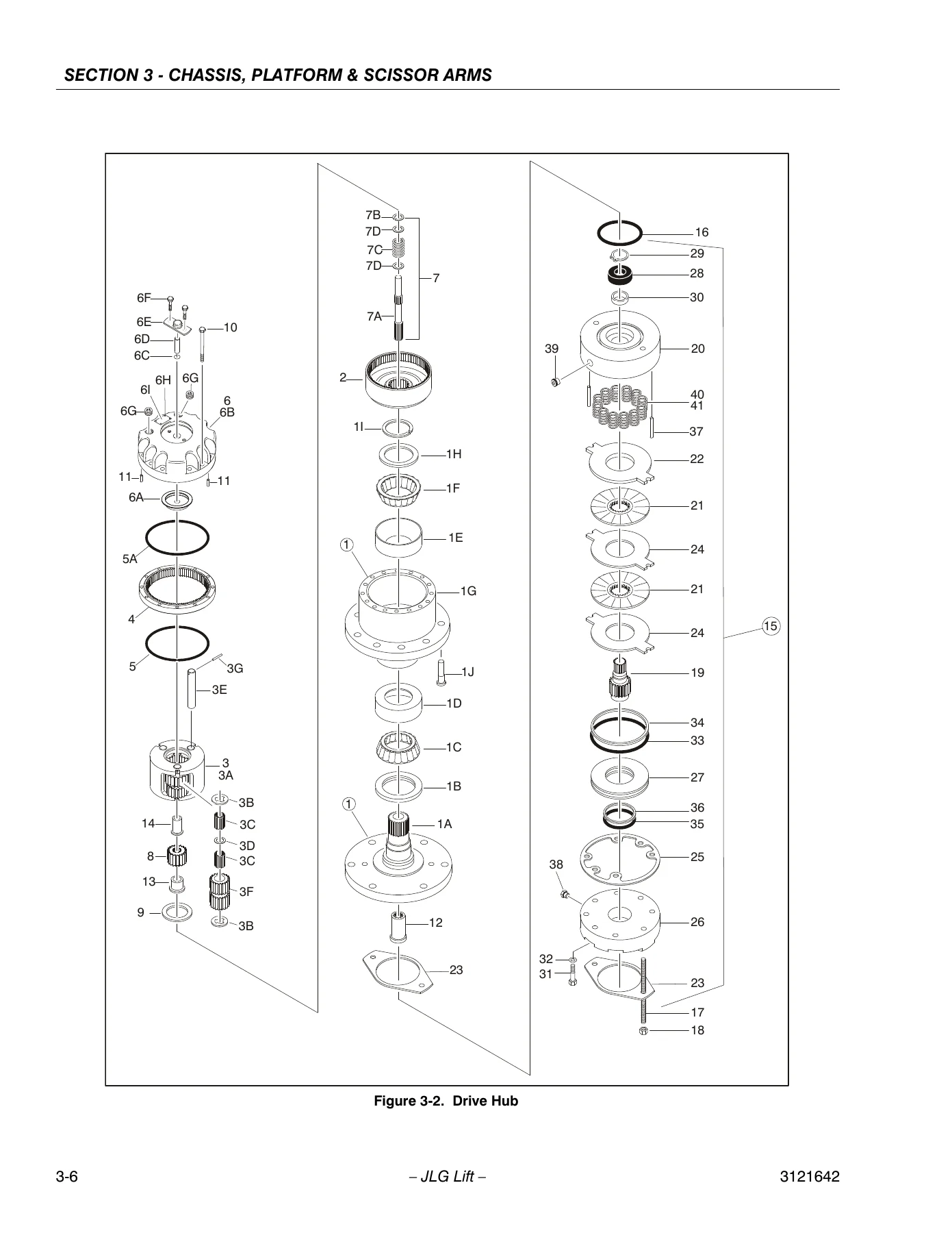
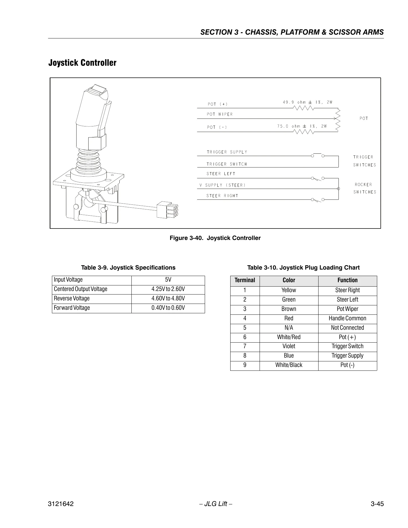
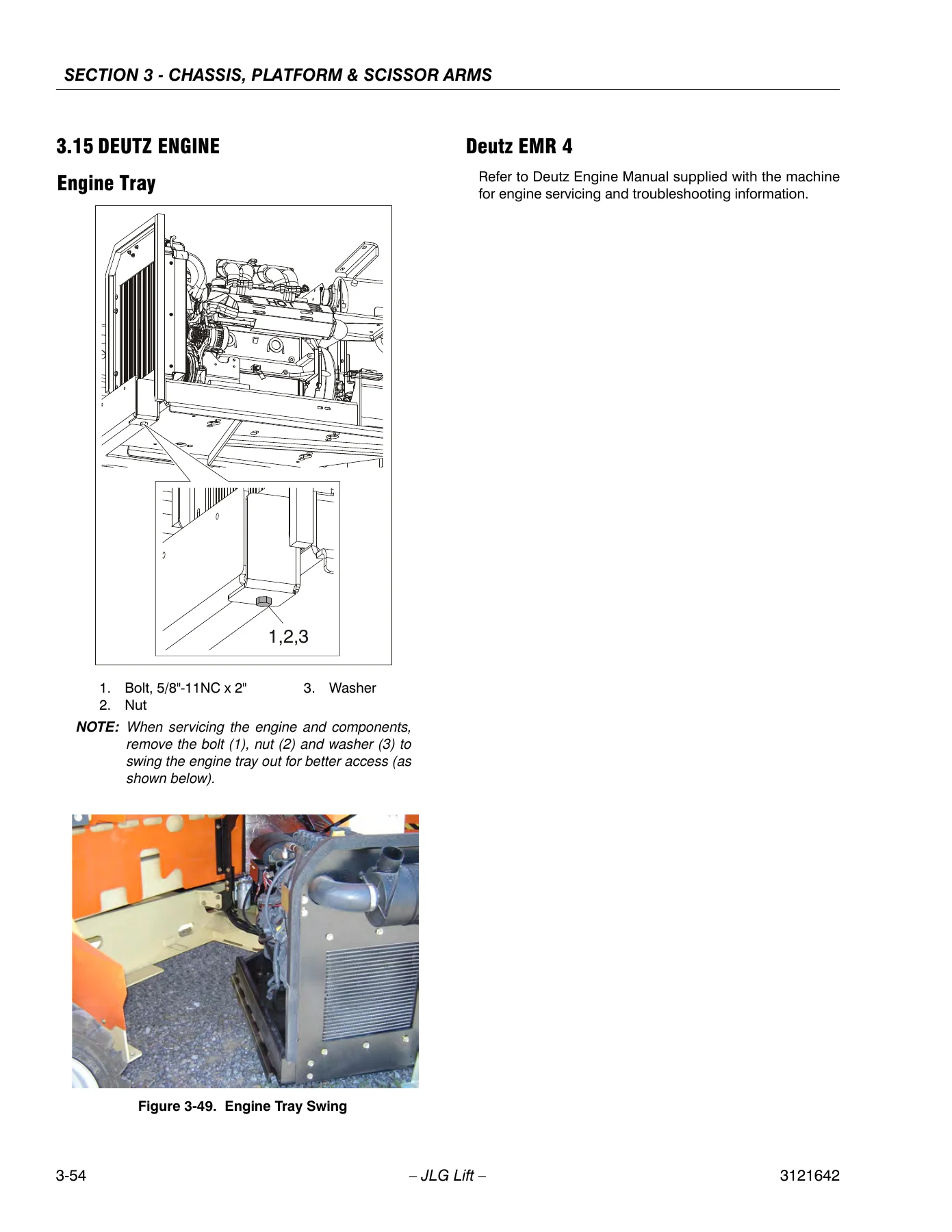
This is the largest mechanical section of the manual. It covers operating characteristics of the leveling jacks, power deck, generator, lift and drive systems, then moves into tyres, wheels and the drive assembly, with a full strip-down and rebuild of the Fairfield drive hub, the Sauer drive motor, and the front axle including the steering assembly and tow bar installation. From there it covers the leveling jacks, the platform and deck extension cylinders, the platform control station and joystick controller, and the scissor arms and lift cylinder removal. Later in the section you get the side compartment covers, the ground control station, the fuel tank, hydraulic tank and battery, the dual fuel/LPG system, and complete removal and installation procedures for the Deutz and GM engine packages, including the exhaust, air cleaner, radiator, pumps, pump coupling and generator. The GM dual fuel system is documented in detail, with the electric lock off, electronic pressure regulator, low pressure regulator, air fuel mixer, electronic throttle control, engine control module, HEGO sensors and the gasoline multi-point fuel injection system, plus the LPG fuel system diagnosis tables.
Section 4 – Hydraulics
The hydraulics section starts with the theory of operation for cylinders and valves, then gives you the cylinder checking procedure and the oscillating axle cylinder test. Cylinder repair is covered step by step, with disassembly, cleaning and inspection, and assembly procedures supported by seal and bushing installation illustrations. The section also covers the drive pump and hydraulic component start-up procedures, the hydraulic gear pump overhaul, the main valve, flow divider valve, leveling jack directional valve, power deck valves and leveling jack valves with their torque specs, and the pressure setting procedures for main relief, lift up relief, steer relief, leveling jack retract relief and power deck reliefs. The axial HI 45 pump gets its own coverage including the electric control module, control solenoids, shaft seal and bearing replacement, charge pump, charge check/HPRV, charge pressure relief valve and pressure limiter valve. Cylinder assemblies close the section, including the steer, lift, oscillating axle, leveling jack and deck extension cylinders.
Section 5 – JLG Control System
This section explains the hand held analyzer, how to connect it at the ground or platform control station, how to move through the top level menus, and how to change the access level using the password so personality and machine setup settings can be adjusted. It also walks through the calibrations you will need in service: elevation sensor calibration at the stow, 26 ft / 30 ft and 30 ft / 36 ft positions, joystick calibration, and tilt sensor calibration with the diagnostic steps for a sensor that will not calibrate. The section ends with the flash code and fault code listing, including the analyzer fault descriptions for power-up issues, platform control issues, ground control issues, cut-out faults, leveling jack and power deck faults, engine faults, battery supply faults, speed sensor faults, CANbus faults and LSS load cell faults, along with the machine configuration programming information and machine model adjustment defaults.
Section 6 – General Electrical Information & Schematics
The final section gives you the electrical foundation for troubleshooting: multimeter basics including grounding, backprobing, min/max, polarity and scale, continuity measurement over long distances, applying silicone dielectric compound to AMP connectors, working with Deutsch DT/DTP and HD30/HDP20 connectors, and switch testing including limit switches and low side/high side wiring. It closes with the electrical schematics for the Deutz and GM machines and the hydraulic schematics, plus the electrical components installation diagrams.
What This JLG 3394RT / 4394RT Manual Lets You Do
With this manual in hand you can carry out the full range of service work on the 3394RT and 4394RT scissor lifts: diagnose a lift that will not level, trace a fault code through the JLG control system, rebuild a Fairfield drive hub or Sauer drive motor, reseal a lift cylinder or leveling jack cylinder, set the main relief and lift up relief pressures, calibrate the elevation sensor or tilt sensor, and service the Deutz D 2.9 L4, Deutz D2011 L03 T41-Flex or GM 3.0L engine package along with its dual fuel/LPG system. The preventive maintenance schedule tells you what to check and when, so you can keep the machine inside its inspection intervals instead of chasing failures.
Working from the correct procedures and the correct torque, pressure and drift values matters on a machine that lifts people. The cylinder drift limits, the high drive cut-out heights, the tilt sensor indicators and the relief settings in this manual are the numbers the 3394RT and 4394RT were built around, and guessing at them is how machines get damaged and operators get hurt. This manual gives you the actual specification rather than an approximation.
IMAGES PREVIEW
The manual is delivered as an instant PDF download, with no shipping and no waiting. You can open it on a laptop or tablet in the shop, print the pages you need for the job at hand, and keep the electrical and hydraulic schematics close by while you work through a fault. Whether you are a fleet mechanic, an independent service technician or an owner maintaining your own JLG lift, this 3121642 Service and Maintenance Manual is the reference you want on the bench.

Reviews
There are no reviews yet.