
JLG 600S 600SJ 660SJ Illustrated Parts Manual 3121207 Rev AE – Boom Lift Parts Catalog PDF
Original price was: $39.95.$23.95Current price is: $23.95.
Complete JLG illustrated parts manual for the 600S, 600SJ and 660SJ boom lifts – document 3121207, Revision AE. Exploded views and parts lists for frame, turntable, boom, platform, cylinders, hydraulics, electrical, decals and options.
Description
JLG 600S, 600SJ and 660SJ Illustrated Parts Manual – Document 3121207, Revision AE
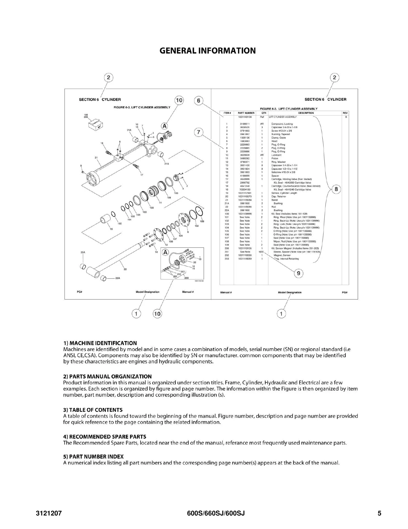
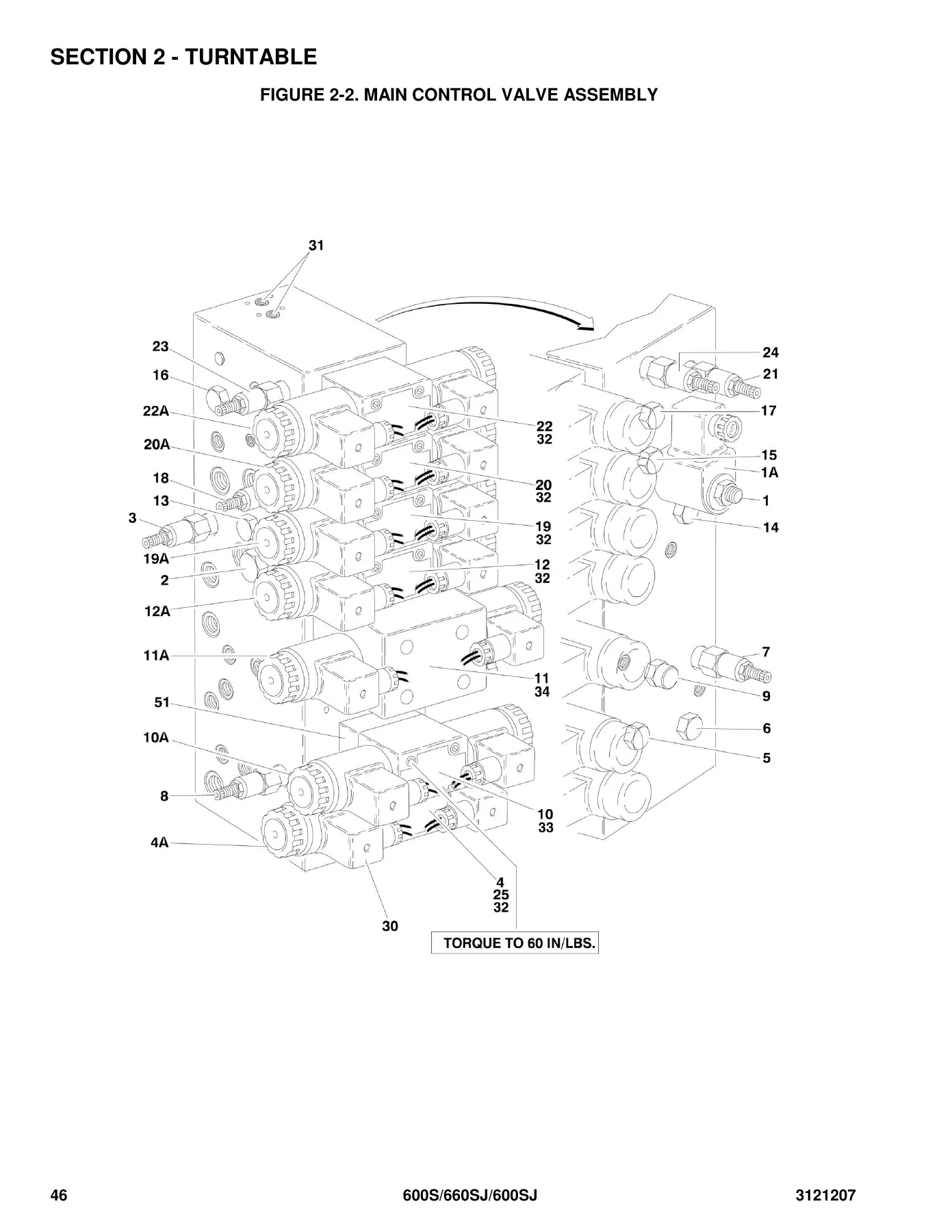
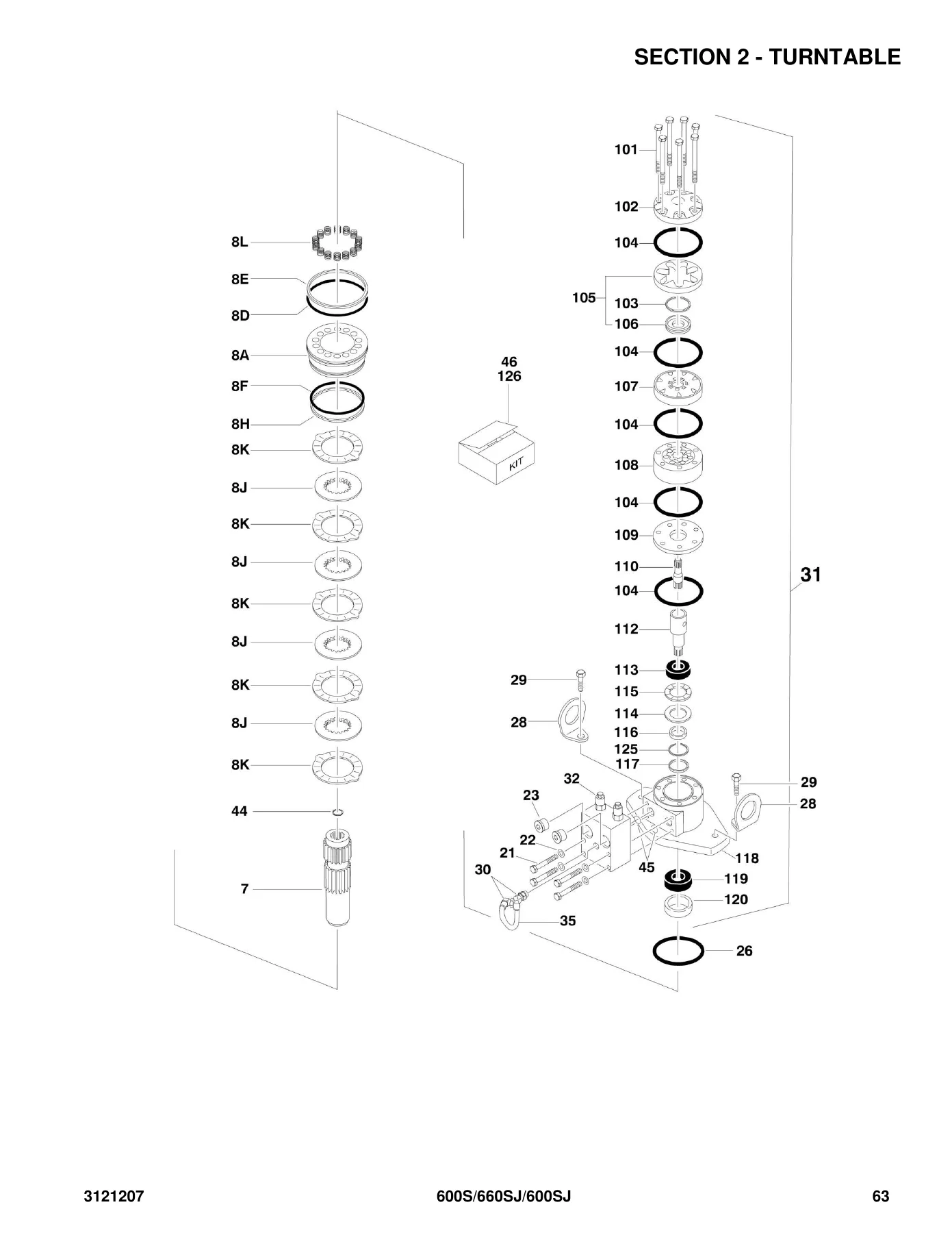
This is the complete illustrated parts manual for the JLG 600S, 600SJ and 660SJ boom lifts. Every figure in the book pairs an exploded illustration with a matching parts list, so you can look at a numbered drawing and read straight across to the item number, JLG part number, quantity, description and revision level for that component. JLG document number 3121207, Revision AE dated September 14, 2018, is the edition covered by this download.
File Details
- Manual type: Illustrated Parts Manual
- Brand / manufacturer: JLG Industries
- Models covered: 600S, 600SJ, 660SJ
- Document number: 3121207
- Revision: AE (September 14, 2018). Original issue June 10, 2005, Revision A
- Language: English
- File format: PDF
- Machine build locations covered: USA and China
- Serial number prefixes: 03 (USA built), B3 (China built)
Chapters Covered in This 600S / 600SJ / 660SJ Parts Manual
The manual is organised into numbered sections, each broken into figures with their own illustration and parts table:
- Section 1 – Frame: 2WD front axle and steering installation; 4WD front axle and steering installation; 4WS rear steering installation; tire and wheel drive installations; drive hub assembly; drive motor assembly (USA built, and USA plus China built); drive valves and shields installation; tow package installation
- Section 2 – Turntable: control valves installations; main control valve assembly; accessory valve assembly; swing drive, turntable bearing and lock installations; swing hub assembly; swing motor assemblies (white roller stator and Parker); swing motor/brake/hub assembly; Caterpillar engine installation; Deutz engine installation; Ford engine installation; GM engine installation (without UGM and with UGM); piston pump assembly; gear pump assembly; tank installations; rotary coupling installation; ground control box assembly (without UGM and with UGM); electrical options installation (turntable mounted); engine tray jack installation; hoods (ABS and steel) and lifting plate installations; 2500W generator installations; 7500W SkyPower generator installations
- Section 3 – Boom: boom installation 600S; boom installation 600SJ and 660SJ; main boom assemblies; rotator assemblies; power track installations
- Section 4 – Platform: platform components installation; fall arrest platform components; platform console assembly; controller assemblies (lift and swing, drive and steer); soft touch system installation; platform bumper padding; SkyGlazier installation; SkyWelder installation (50Hz and 60Hz); welder assembly; SkyCutter installation; plasma cutter assembly; pipe racks installation; SkyAir air compressor installation; air compressor assembly
- Section 5 – Cylinder: axle lockout cylinder assembly; level cylinder assembly (platform slave); level cylinder service replacement; jib lift cylinder; main boom lift cylinder; master cylinder assembly; steer cylinder assembly; telescope cylinder assemblies
- Section 6 – Hydraulic: drive and steer diagrams (2WD/2WS and 4WD/2WS); oscillating axle diagram; standard hydraulic diagram; hydraulic diagram list
- Section 7 – Electrical: electrical diagram list; harness components installation (without UGM and with UGM); AC cables installation (CE German and CE UK specs)
- Section 8 – Decals: decal installations by specification and build location
- Section 9 – Recommended Service Parts Stock: standard parts and variable parts lists
- Section 10 – Special Options: special options listing
- Part Number Index: a numerical index of every part number in the manual with the page number where it appears
What makes this JLG 600S 600SJ 660SJ parts book genuinely useful is the way it is built for parts identification rather than general reading. Each parts list is arranged by item number, JLG part number, quantity, description and revision level. Assemblies that are not sold in pieces are flagged in the quantity column, non-serviced parts are marked NSS, and discontinued numbers are marked NLA with the replacement number printed beside them wherever JLG supplied one. Where a component sits inside a larger assembly, its description is indented under the parent item so you can see at a glance which parts belong together. A full abbreviation and symbols key is included, covering everything from ANSI and CE through to UGM, ORFS, NPT and the hydraulic and electrical shorthand used throughout the figures.
Serial Number Breaks Are Built Into the Listings
The 600S, 600SJ and 660SJ changed considerably over the production run, and this edition of the parts manual handles that properly. Rather than giving a single number for a part that changed, the tables list the correct part number against the serial number range it applies to. You will see this on the front axle and steering installations, the drive hub and drive motor assemblies, the swing hub and swing motor assemblies, the engine installations, the ground control box assemblies, the rotary coupling, the hoods, the platform console box, the steer cylinder, the level and master cylinders, and the decal installations. USA built and China built machines are identified separately throughout, with the USA prefix 03 and the China prefix B3 used as the marker.
One detail worth knowing before you order: JLG notes that USA built machines with serial numbers 0300170082 and 0300170091 were also built to the same specification as USA built machines from serial number 0300171769 onward, and that certain China built machines were built to the same specification as China built machine serial number 0300000970 onward. Those machines are covered by a different parts manual, JLG publication 3121299.
Engine, Generator and Attachment Coverage
The turntable section carries full parts breakdowns for the engine installations used across these models, including Caterpillar 3044 Tier III and C3.4 Tier IVi machines, Deutz machines, Ford engine machines and GM 3.0L machines, with the GM installation split between machines without UGM and machines with UGM. Pump assemblies, tanks, rotary coupling and the ground control box are all covered alongside them.
Generator coverage includes the 2500W installations for Caterpillar, Deutz, Ford and GM machines, and the 7500W SkyPower installations for Caterpillar and Deutz, Ford, and GM engines, complete with junction box assemblies, control box assemblies, receptacles, breakers, pulleys, belts and harness components. In the platform section you get the SkyGlazier tray assembly, the SkyWelder installation for both 50Hz and 60Hz power supplies with the full welder assembly breakdown, the SkyCutter installation, the plasma cutter assembly and torch assembly, pipe racks, and the SkyAir air compressor installation with the complete compressor assembly, pump, motor, valves, filters and decals.
Who This JLG 600S / 600SJ / 660SJ Parts Manual Is For
This is a working parts catalogue. It is the reference you reach for when a cylinder needs resealing, when a drive motor or swing motor has to be replaced, when a valve cartridge is leaking, when a hose has to be matched to the right circuit, when a decal has to be reordered for a specific specification, or when you simply need to confirm that the part number you are about to order is the one that matches your machine’s serial number. Independent workshops, rental fleets, dealership parts counters and owners maintaining their own boom lift all use the same information, because the exploded views make it possible to identify a component visually before you commit to buying it.
Ordering the wrong part because two similar-looking components share a section is one of the most expensive mistakes in boom lift maintenance, and serial number break tables are exactly what prevent it. This manual gives you the illustration, the item number, the part number and the serial range in one place, so the part you receive is the part that fits.
Your JLG 600S 600SJ 660SJ illustrated parts manual is delivered as an instant PDF download – no shipping, no waiting on a courier, and no physical book to lose in the workshop. Open it on a laptop, tablet or phone at the machine, search the part number index for a number you already have, print the figure you are working from and take it with you, or print the whole book and keep it in the shop. Once payment is complete the file is yours to download and use straight away.
Reviews
There are no reviews yet.