★ TRUSTED BY 321,897+ PROFESSIONALS WORLDWIDE
🏒
Trusted Business
Verified & Licensed
πŸ›‘οΈ
Virus Free Files
100% Safe Downloads
πŸ”’
Secure Payment
SSL Protected
⚑
Instant Delivery
Available Immediately
Sale!

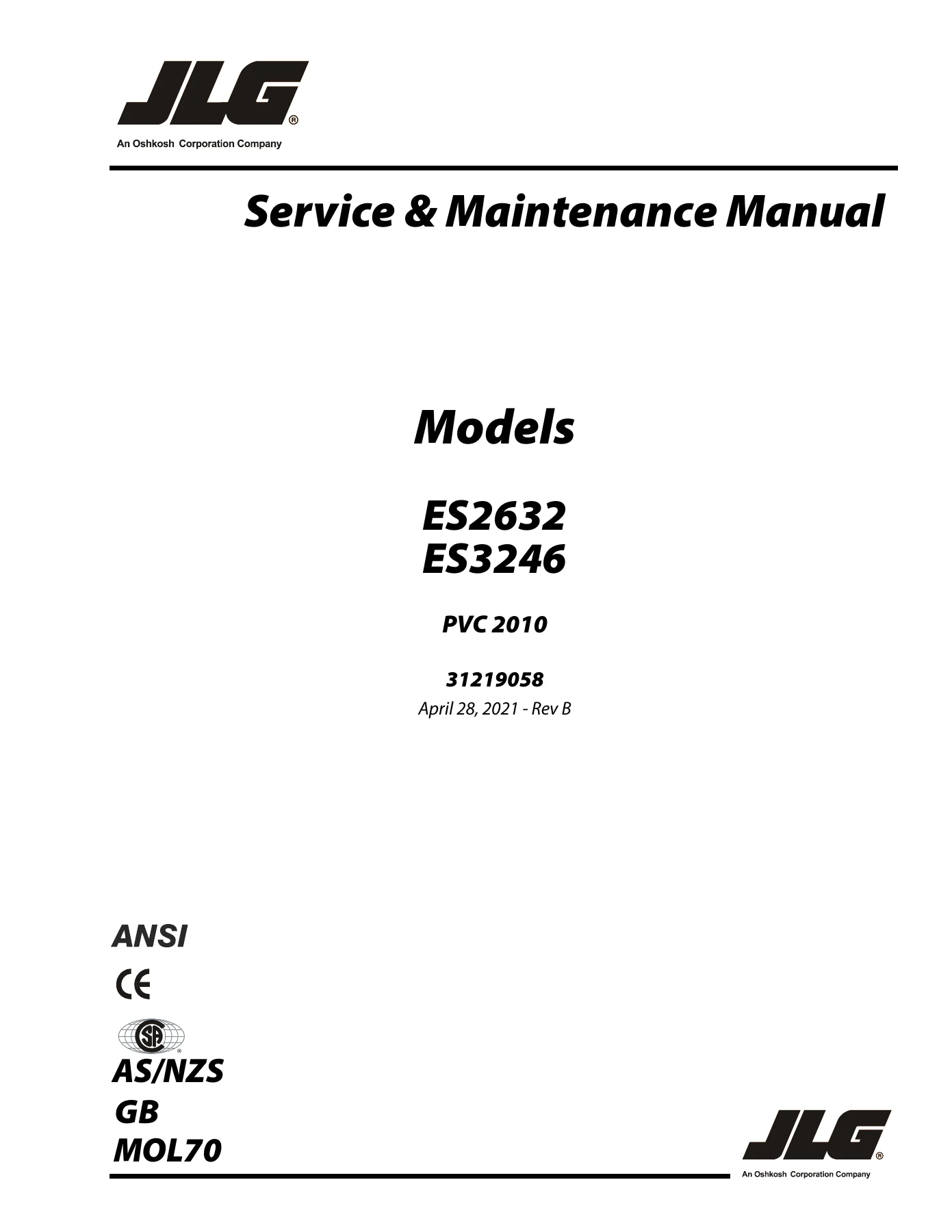
JLG ES2632 & ES3246 Scissor Lift Service & Maintenance Manual 31219058 Rev B

Original price was: $39.95.Current price is: $24.95.

Complete JLG service and maintenance manual for ES2632 and ES3246 scissor lifts. Covers hydraulic systems, wiring schematics, JLG control system, LSS calibration, diagnostic trouble codes, chassis and scissor arm repair, torque specs, and preventive maintenance schedules. 200-page PDF, Rev B, document 31219058.

⚑
Instant PDF Download
Available immediately
πŸ’Ύ
Save to Your Device
Download & keep forever
πŸ›‘οΈ
Antivirus Scanned
100% virus-free
🌍
Trusted Worldwide
175,000+ customers

Description

JLG ES2632 & ES3246 Scissor Lift Service & Maintenance Manual – 31219058 Rev B

This is the complete JLG ES2632 & ES3246 Scissor Lift Service & Maintenance Manual, published under document number 31219058, revision B, dated April 28, 2021. It is the same technical reference used by qualified JLG equipment mechanics to inspect, service, repair, and maintain these two scissor lift models. Whether you own an ES2632 or an ES3246, this manual walks through every major system on the machine – from the hydraulic lift circuit and steer assembly to the JLG control system, Load Sensing System, and full electrical schematics.

File Details

  • Manual type: Service and Maintenance Manual
  • Brand: JLG
  • Models covered: ES2632, ES3246
  • Document number: 31219058
  • Revision: Rev B
  • Revision date: April 28, 2021 (Original Issue A – November 24, 2020)
  • Language: English
  • Page count: 200 pages
  • File format: PDF

Chapters Covered

  • Section A – Introduction / Maintenance Safety Precautions: General safety, hydraulic system safety, maintenance warnings
  • Section 1 – Specifications: Operating specifications, platform capacities, machine dimensional data, tires, batteries, motors, battery charger specs, limit switch activation, lubrication, hydraulic oil, hydraulic pressure settings, cylinder specifications, serial number location, critical stability weights, major component weights, torque requirements, thread locking compound, SAE and metric torque charts
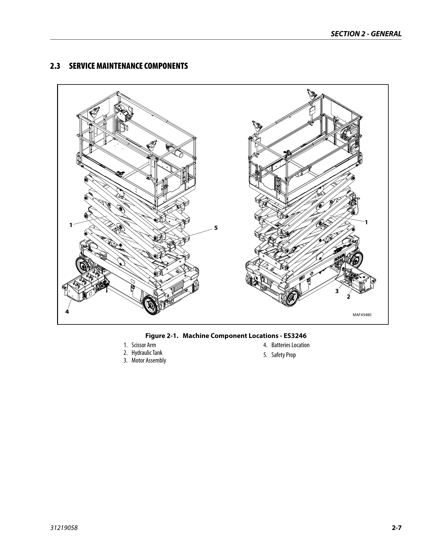
  • Section 2 – General: Machine preparation, inspection and maintenance, pre-start inspection, pre-delivery and frequent inspection, annual machine inspection, preventive maintenance and inspection schedule, service maintenance components, scissor arm safety prop, hydraulic oil check procedure, service and guidelines
  • Section 3 – Chassis & Scissor Arms: Left and right side compartment components, battery removal and maintenance, battery charging, DC/AC power inverter installation, logic control module installation, drive control module, drive module electrical evaluation, drive motor electrical evaluation, ground control station, platform control station, tilt sensor installation, arm angle sensor, pothole protection system components, steer and spindle assembly components, arms and platform positioning and support, platform removal, scissor arms removal
  • Section 4 – Basic Hydraulics Information & Schematics: Cylinders theory of operation, valves theory of operation, pump/motor, hydraulic tank installation, hydraulic manifold assembly, pump/motor/tank assembly, rear wheel hub and frame clamps installation, pressure setting procedure, cylinder checking procedure, lift cylinder removal and installation, cylinder repair, hydraulic schematics
  • Section 5 – JLG Control System: Hand held analyzer, diagnostic port, joystick calibration, tilt sensor calibration, rotary angle sensor calibration, updating software, machine configuration programming information, machine model adjustment (personality settings)
  • Section 6 – LSS (Load Sensing System) Service: LSS theory of operation, analyzer information, calibration preparation, calibration and verification procedure, testing, LSS connector pin assignments, LSS troubleshooting
  • Section 7 – Diagnostic Trouble Codes: Introduction, system fault/DTC indication, diagnostic trouble codes, DTC check tables
  • Section 8 – Basic Electrical Information & Schematics: Multimeter basics, silicone dielectric compound application, dielectric grease application, AMP connectors, Deutsch connectors, switches, electrical schematics

This service and maintenance manual gives a technician everything needed to keep an ES2632 or ES3246 scissor lift operating safely and correctly. The document begins with the safety precautions that must be observed before any work starts, then moves into the full specifications chapter – capacities, dimensional data, battery and charger specs, hydraulic pressures, cylinder dimensions, and critical stability weights. From there, it covers the inspection and maintenance program: what to check before each shift, what a frequent inspection involves, and what an annual machine inspection requires. The chassis and scissor arm section walks through component locations, battery service, the logic and drive modules, ground and platform control stations, tilt and angle sensors, the pothole protection system, and the complete process for removing and reinstalling the platform and scissor arms.

The hydraulics chapter explains how the lift and steer cylinders work, how the control valves operate, and how to set main relief and steer pressures. It includes the lift cylinder removal and installation procedure, cylinder checking, and full cylinder repair steps with seal installation guidance. The JLG control system section covers the hand held analyzer, joystick and tilt sensor calibration, software updates, machine configuration, and personality settings. The Load Sensing System chapter is particularly detailed – covering theory, calibration with and without test weights, verification, testing, connector pin assignments, and troubleshooting. Finally, the diagnostic trouble codes chapter lists the DTCs used by the control system, and the electrical chapter provides multimeter basics, connector service procedures, and the complete electrical schematics for both models.

What This Manual Enables You to Do

With this JLG ES2632 & ES3246 Scissor Lift Service & Maintenance Manual on hand, you can carry out scheduled preventive maintenance, diagnose hydraulic and electrical faults, calibrate the JLG control system and Load Sensing System, read and clear diagnostic trouble codes, rebuild lift and steer cylinders, replace the logic and drive modules, service the pothole protection system, and perform structural work on the scissor arm assembly. The torque charts, pressure settings, and cylinder specifications mean you can tighten fasteners and set relief valves to the exact values JLG specifies rather than working from guesswork.

Correct procedures and specifications matter on aerial work platforms because the consequences of an incorrectly assembled hydraulic circuit, a miscalibrated load sensor, or a loose structural fastener go well beyond a machine that will not start. Following the manual’s steps and torque values is how you keep the lift safe to operate. Every procedure in this manual is written for the specific ES2632 and ES3246 models, with their own bore diameters, stroke lengths, relief pressures, and personality settings called out separately where the two machines differ.

Complete PDF Bookmark Tree

Complete Bookmarks

The complete bookmarks in the β€œJLG ES2632 & ES3246 Scissor Lift Service & Maintenance Manual 31219058 Rev B” are as follows:

31219058_B_ES2632, ES3246_JLG_Service_Englishp. 1
Section A. Introduction – Maintenance Safety Precautionsp. 3
Generalp. 3
Hydraulic System Safetyp. 3
Maintenancep. 3
Table of Contentsp. 5
List of Figuresp. 10
List of Tablesp. 12
Section 1. Specificationsp. 13
1.1 Operating Specificationp. 13
Machine Specificationp. 13
Platform Capacitiesp. 14
Machine Dimensional Datap. 14
Tiresp. 14
Batteriesp. 15
Motorsp. 15
Battery Chargerp. 16
1.2 Limit Switch Activationp. 17
Tilt Alarmp. 17
1.3 Lubricationp. 17
Capacitiesp. 17
Specificationsp. 17
1.4 Hydraulic Oilp. 18
1.5 Hydraulic Pressure Settingsp. 20
1.6 Hydraulic Cylinder Specificationsp. 20
1.7 Serial Number Locationp. 20
1.8 Critical Stability Weightsp. 20
1.9 Major Component Weightsp. 21
1.10 Torque Requirementsp. 21
1.11 Thread Locking Compoundp. 22
1.12 Torque Chartsp. 23
SAE Fastener Torque Chartp. 23
SAE Fastener Torque Chart (Continued)p. 24
SAE Fastener Torque Chart (Continued)p. 25
SAE Fastener Torque Chart (Continued)p. 26
SAE Fastener Torque Chart (Continued)p. 27
SAE Fastener Torque Chart (Continued)p. 28
Metric Fastener Torque Chartp. 29
Metric Fastener Torque Chart (Continued)p. 30
Metric Fastener Torque Chart (Continued)p. 31
Metric Fastener Torque Chart (Continued)p. 32
Section 2. Generalp. 33
2.1 Machine Preparation, Inspection, and Maintenancep. 33
Generalp. 33
Preparation, Inspection, and Maintenancep. 33
Pre-Start Inspectionp. 33
Pre-Delivery Inspection and Frequent Inspectionp. 33
Annual Machine Inspectionp. 33
Preventative Maintenancep. 33
2.2 Preventive Maintenance and Inspection Schedulep. 35
Maintenance and Inspection Schedule Codes:p. 35
2.3 Service Maintenance Componentsp. 39
Scissor Arm – Safety Propp. 40
Hydraulic Oil Check Procedurep. 41
2.4 Service and Guidelinesp. 42
Generalp. 42
Safety and Workmanshipp. 42
Cleanlinessp. 42
Components Removal and Installationp. 43
Component Disassembly and Reassemblyp. 43
Pressure-Fit Partsp. 43
Bearingsp. 43
Gasketsp. 43
Bolt Usage and Torque Applicationp. 43
Hydraulic Lines and Electrical Wiringp. 43
Hydraulic Systemp. 43
Lubricationp. 43
Batteryp. 43
2.5 Lubrication and Informationp. 44
Hydraulic Systemp. 44
Hydraulic Oilp. 44
Changing Hydraulic Oilp. 44
2.6 Cylinder Drift Testp. 45
Platform Driftp. 45
Cylinder Driftp. 45
2.7 Pins and Composite Bearing Repair Guidelinesp. 45
Section 3. Chassis & Scissor Armsp. 47
3.1 Left and Right Side Compartment Componentsp. 47
3.2 Battery Removal/Maintenancep. 49
Battery Quick-Disconnectp. 49
Battery Maintenance and Safety Practicesp. 50
3.3 Battery Chargingp. 50
Delta-Q – Battery Chargerp. 51
Green Power – Battery Charger – (China (GB) Only)p. 51
Eagle Performance – Battery Chargerp. 52
Battery Charger Maintenancep. 52
3.4 DC/AC Power Inverter Installation – Optionp. 56
3.5 Logic Control Module Installationp. 57
Module Accessp. 57
Removing Module from Machinep. 57
3.6 Drive Control Modulep. 58
Removalp. 58
Installationp. 58
3.7 Drive Module Electrical Evaluationp. 60
3.8 Drive Motor Electrical Evaluationp. 61
3.9 Ground Control Stationp. 62
Components Locationp. 62
Removalp. 62
Installationp. 62
3.10 Platform Control Stationp. 64
Overview of Control Station Componentsp. 64
Installation/Removalp. 64
Control Station Disassemblyp. 65
Joystick Controllerp. 66
3.11 Tilt Sensor Installationp. 67
Tilt Sensor Removalp. 67
Tilt Sensor Installationp. 67
3.12 Arm Angle Sensorp. 68
Arm Angle Sensor Installationp. 69
3.13 Pothole Protection System Componentsp. 71
3.14 Steer and Spindle Assembly Componentsp. 74
Drive Motor Covers Installation – Optionp. 76
Tire Wear and Damagep. 77
Wheel and Tire Replacementp. 77
Wheel Installationp. 77
3.15 Arms and Platform Positioning and Supportp. 78
3.16 Platform Removalp. 78
3.17 Scissor Arms Removalp. 78
Removing Scissor Arm Assembly as a Complete Unitp. 78
Removing/Installing Scissor Arms Individuallyp. 78
Section 4. Basic Hydraulics Information & Schematicsp. 93
4.1 Cylinders – Theory of Operationp. 93
4.2 Valves – Theory of Operationp. 93
Solenoid Control Valves (Bang-Bang)p. 93
Relief Valvesp. 93
Crossover Relief Valvesp. 93
Proportional Valvep. 93
Manual Descent Valvep. 93
4.3 Pump/Motorp. 94
Pump Motor Electrical Evaluationp. 94
4.4 Hydraulic Tank Installationp. 96
Motor Cover/Motor Installationp. 97
Preventative Maintenance – Brush Wear – Dust Removal Procedurep. 97
Motor Brush Installationp. 97
4.5 Hydraulic Manifold Assemblyp. 98
4.6 Pump, Motor/Tank Assemblyp. 99
4.7 Rear Wheel Hub and Frame Clamps Installationp. 103
4.8 Pressure Setting Procedurep. 104
Machine Model Pressure settingp. 104
Main Relief Adjustmentp. 104
Steer Left Pressure Adjustmentp. 104
Steer Right Pressure Adjustmentp. 104
4.9 Cylinder Checking Procedurep. 105
4.10 Lift Cylinder Removal Installationp. 105
Lift Cylinder – LSS Pressure Sensor Locationp. 106
4.11 Cylinder Repairp. 110
Disassemblyp. 110
Cleaning and Inspectionp. 111
Assemblyp. 112
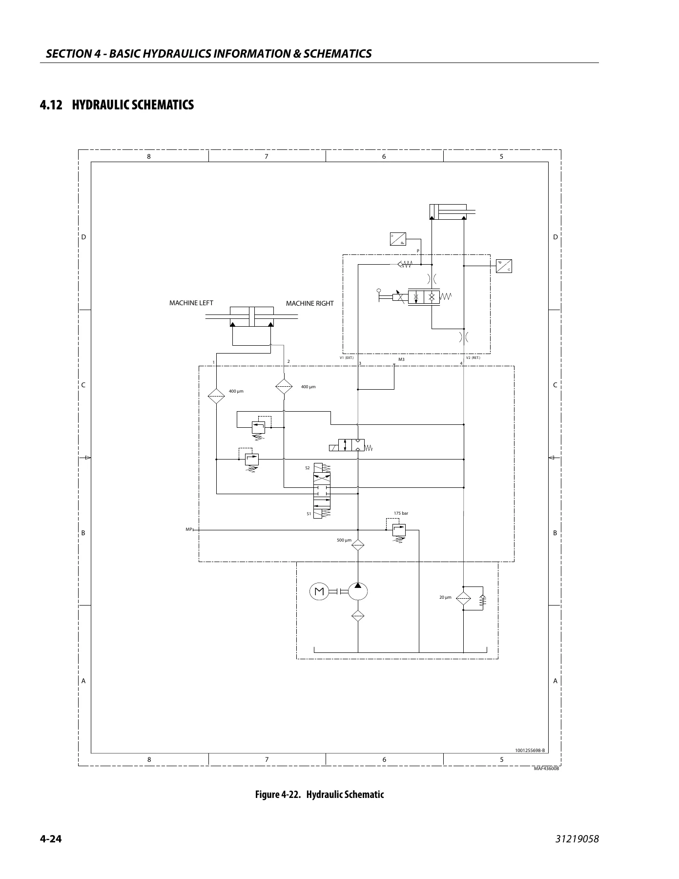
4.12 Hydraulic Schematicsp. 116
Section 5. JLG Control Systemp. 119
5.1 Hand Held Analyzerp. 119
Diagnostic Portp. 119
To Connect the Hand Held Analyzer:p. 119
Using the Analyzer:p. 120
Changing the Access Level of the Hand Held Analyzer:p. 121
Adjusting Parameters Using the Hand Held Analyzerp. 122
Machine Setupp. 122
5.2 Joystick Calibrationp. 123
5.3 Tilt Sensor Calibrationp. 123
Tilt Sensor Failure Troubleshootingp. 124
5.4 Rotary Angle Sensor Calibrationp. 124
5.5 Updating Softwarep. 124
5.6 Machine Configuration Programming Informationp. 131
5.7 Machine Model Adjustment (Personality Settings)p. 132
Section 6. LSS (Load Sensing System) Servicep. 133
6.1 LSS (Load Sensing System)p. 133
Theory of Operationp. 133
6.2 Analyzer Informationp. 135
Personalities Menup. 135
Diagnostic Menup. 135
6.3 Calibration Preparationp. 137
6.4 Calibration and Verification Procedurep. 138
Empty Platform Calibrationp. 138
Loaded Platform Calibrationp. 138
LSS Verificationp. 139
Partial Height Calibrationp. 139
6.5 Testingp. 139
6.6 LSS Connector Pin Assignmentsp. 140
6.7 LSS Troubleshootingp. 141
Section 7. Diagnostic Trouble Codesp. 143
7.1 Introductionp. 143
System Fault/DTC Indicationp. 143
7.2 Diagnostic Trouble Codes (DTC)p. 143
7.3 DTC Check Tablesp. 144
Section 8. basic Electrical Information & Schematicsp. 173
8.1 Generalp. 173
8.2 Multimeter Basicsp. 173
Groundingp. 173
Backprobingp. 173
Min/Maxp. 173
Polarityp. 173
Scalep. 173
Voltage Measurementp. 174
Resistance Measurementp. 174
Continuity Measurementp. 175
Current Measurementp. 175
Continuity Measurement Over Long Distancesp. 176
Requirements:p. 176
Procedurep. 176
8.3 Applying Silicone Dielectric Compound to AMP Connectorsp. 176
8.4 Dielectric Grease Applicationp. 177
Installationp. 177
AMP Mate-N-Lokp. 177
AMP Fastonp. 177
AMP Micro-Fitp. 177
AMP Mini Fit Jrp. 177
Mini Fit Srp. 177
DIN Connectorsp. 178
Exceptionsp. 178
8.5 AMP Connectorp. 179
Assemblyp. 179
Disassemblyp. 181
Wedge Lockp. 181
Service – Voltage Readingp. 181
8.6 Deutsch Connectorsp. 183
DT/DTP Series Assemblyp. 183
DT/DTP Series Disassemblyp. 183
HD30/HDP20 Series Assemblyp. 184
HD30/HDP20 Series Disassemblyp. 184
8.7 Switchesp. 185
Basic Checkp. 185
Limit Switchesp. 185
Automatic Switchesp. 185
Switch Wiring – Low Side, High Sidep. 185
8.8 Electrical Schematicsp. 187


IMAGES PREVIEW

JLG ES2632 & ES3246 Scissor Lift Service & Maintenance Manual 31219058 Rev B β€” PDF page 1 preview
JLG ES2632 & ES3246 Scissor Lift Service & Maintenance Manual 31219058 Rev B β€” PDF page 39 preview
JLG ES2632 & ES3246 Scissor Lift Service & Maintenance Manual 31219058 Rev B β€” PDF page 116 preview

Instant PDF Delivery

This JLG ES2632 & ES3246 service manual is delivered as an instant PDF download. There is no shipping, no waiting for a physical book, and no restriction on where you use it – open it on a laptop in the shop, a tablet at the machine, or a phone in the field. You can print the pages you need for a specific job, whether that is a single hydraulic schematic, a torque chart, or the full cylinder repair procedure. Once the file is downloaded, it stays with you.
Reviews

There are no reviews yet.

Be the first to review “JLG ES2632 & ES3246 Scissor Lift Service & Maintenance Manual 31219058 Rev B”

What Our Customers Say

β˜…β˜…β˜…β˜…β˜… Live reviews from customers
Loading customer reviews...
0
    0
    Your Cart
    Your cart is emptyReturn to Shop
    πŸ›’
    Recently Purchased
    πŸ•’ verified order