
JLG SkyTrak 8042 10042 10054 Illustrated Parts Manual PDF – 31200732
Original price was: $59.95.$39.95Current price is: $39.95.
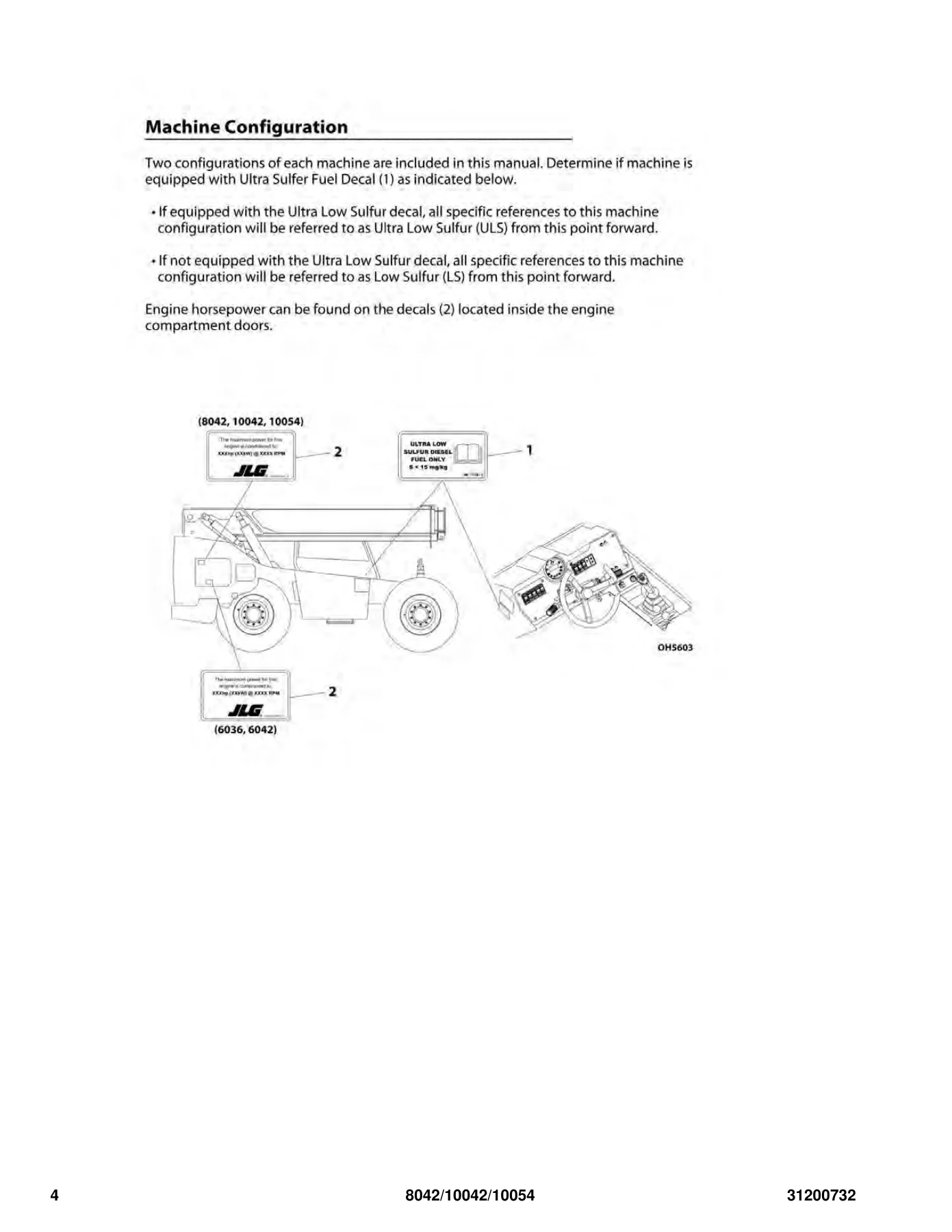
Complete illustrated parts manual for JLG SkyTrak 8042, 10042 and 10054 telehandlers. Document 31200732 with exploded views, part numbers and spare parts listings for ULS and LS configurations.
Description
JLG SkyTrak 8042 10042 10054 Illustrated Parts Manual – Document 31200732
This illustrated parts manual covers the JLG SkyTrak 8042, 10042 and 10054 telehandler models in both Ultra Low Sulfur (ULS) and Low Sulfur (LS) configurations. Published under document number 31200732, this manual provides exploded-view illustrations, part numbers and complete spare parts listings for every major system on these machines. Whether you are ordering a replacement wear pad, a hydraulic cylinder seal kit, or a complete boom section, this manual gives you the exact part numbers you need to get the right component the first time.
File Details
- Manual Type: Illustrated Parts Manual
- Brand: JLG SkyTrak
- Models Covered: 8042, 10042, 10054
- Document Number: 31200732
- Language: English
- Page Count: 428
- File Format: PDF
- Revision: O (latest revision shown)
- Date: April 17, 2018 (latest revision date)
Chapters Covered
- Section 1 – Frame and Attaching Parts
- Section 2 – Boom
- Section 3 – Attachments
- Section 4 – Engine and Attaching Parts
- Section 5 – Drive Train
- Section 6 – Cab
- Section 7 – Controls
- Section 8 – Hydraulic Circuits
- Section 9 – Hydraulic Components
- Section 10 – Electrical
- Section 11 – Decals
- Section 12 – Recommended Spare Parts
- Part Number Index
Section 1 – Frame and Attaching Parts
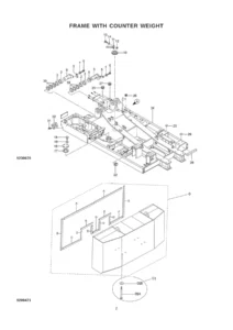
Detailed breakdown of the frame installation for the 8042, 10042 and 10054, including frame weldment, counterweight hold-down plates, rear and front counterweights, and counterweight mounting angles. Covers the frame covers for both early and late serial number ranges, with door panels, latches, keys, insulation tape, well nuts and vinyl edge trim. The outrigger installation for the 10042 and 10054 is covered with mounting brackets, outrigger frames, legs, pads, pivot pins, bushings and grease fittings.
Section 2 – Boom
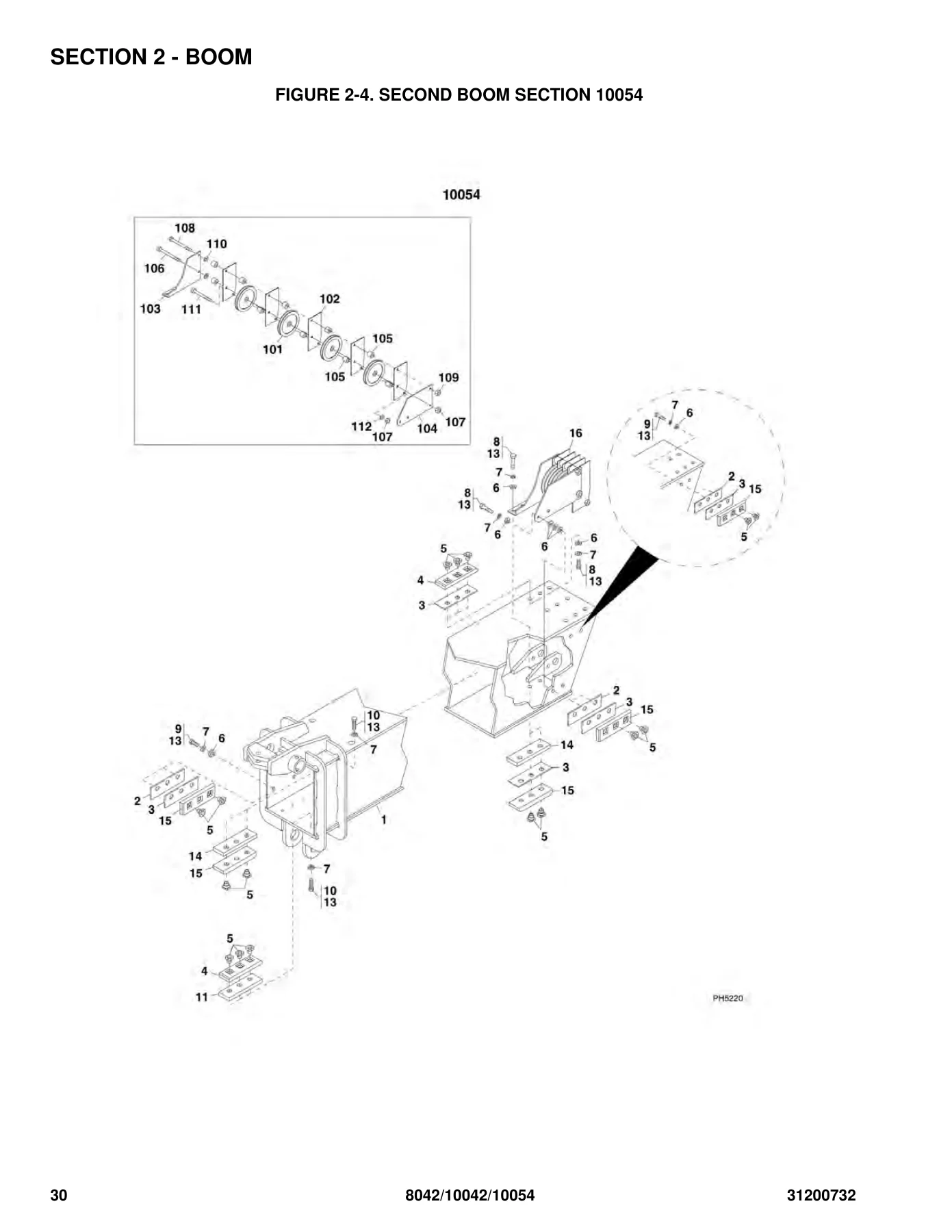
The complete boom assembly is broken down into its individual sections: first boom section, second boom section (8042/10042 and 10054 variants), third boom section (8042/10042 and 10054), and fourth boom section for the 10054. Includes all wear pads, wear pad inserts, shims, spacers, and the capscrews and lockwashers that secure them. Extend chains and retract chains are detailed for both model groups, with chain clevis assemblies, anchor clevises, yoke assemblies, sheave assemblies, chain pins and retaining rings. The quick attach assembly is covered with torsion spring, latch, spacer, lock pin and mounting hardware.
Section 3 – Attachments
This section covers every attachment offered for the SkyTrak line. Tilt carriages are shown for both prior-to and after-serial-number ranges, including 50-inch, 60-inch and 72-inch versions with fork pins, collars, lift lugs, shackles and decals. Side tilt carriage, 50-inch side shift carriage, 50-inch dual fork carriage, and 90-degree swing carriage are each fully illustrated with cylinders, hoses, adapters, quick disconnects, bearings, pins and wear pads. The sheet material handler, forks (cubing, pallet, dual taper, and fork extensions), fork-mounted platform, lifting hook, fork pin lock installation, buckets (72-inch, 96-inch, 102-inch), grapple bucket, truss boom (12-ft and 15-ft), 12-ft truss boom with winch, 8-ft mast and adjustable truss boom are all included with their respective components and part numbers.
Section 4 – Engine and Attaching Parts
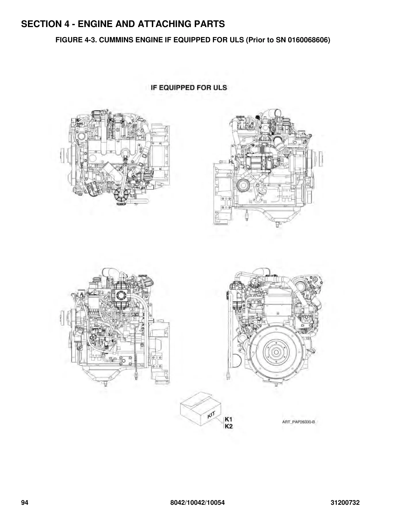
Engine installation details are provided for both ULS and LS configurations, covering engine mounts, brackets, rebound washers, rubber mounts and center bonded mounts. The Cummins QSB3.3 engine is broken down for both 100HP Tier 4i (ULS) and 110HP Tier 3 (LS) versions, with fan belt, fan spacer, alternator, starter, oil filter element, dipstick, fuel pump, thermostat, fuel filters, injectors, engine harness and flywheel. Fuel tank and lines, radiator and cooling installation (including radiator assembly, transmission cooler, water/glycol cooler, charge air cooler and oil cooler), air cleaner installation, exhaust installation, and the isolation coupler are all covered with their respective plumbing, clamps, hoses and mounting hardware.
Section 5 – Drive Train
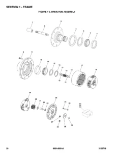
Drive train components are covered in extensive detail, starting with axle installations for the 8042 and 10042/10054. The front axle is broken down into input, limited slip differential, axle casing, M-disc brake, brake, joint housing and planetary drive. The rear axle follows the same structure with input, differential, axle casing, M-disc brake, joint housing and planetary drive. The ZF transmission installation is covered along with its engine connection and convertor, input shafts, gearbox housing, coupling groups 1 through 4, reversing gear groups 1 and 2, output, control unit, valve housing assembly, valve block assembly, and oil pump and filter. Fender installation and wheel assemblies for the 8042 and 10042/10054 complete the section.
Section 6 – Cab
Cab installation and cab assembly are covered with mounting hardware, steps, mirrors, manual holder, tilt angle gauge and brush strips. The cab door assembly is shown in two versions based on serial number, with door weldments, handles, latches, linkages, glass, seals, hinges and hardware. Soft cab enclosure, wipers (front windshield and skylight), operator’s seat (with suspension seat, back cushion kit, seat belt kit, tether kit and slide kit), cab heater (with heater kit, hoses, louvers, control panel and wiring), and rear dropout window installation are all included.
Section 7 – Controls
Brake pedal assembly, accelerator (throttle pedal adaptor, throttle pedal and adaptor plate), steering column (steering wheel, horn switch, column and transmission range selector shifter), boom control (joystick with gate, knob, boot and control cables), frame level and attachment tilt control (joystick, control cables and hardware), and auxiliary control (controller, knob, boot, control cable and support) are all detailed with their mounting hardware and linkage components.
Section 8 – Hydraulic Circuits
Circuit-by-circuit breakdowns of the hydraulic system include the supply circuit, dump circuit (ULS and LS), steer select circuit, service brake circuit, lift cylinder circuit, extend/retract cylinder circuit (8042/10042 and 10054), attachment tilt and tilt compensation cylinder circuit, auxiliary hydraulic circuit, frame level and Stabil-Trak cylinder circuit, outrigger circuit (10042/10054), transmission cooler, and main control valve installation. Each circuit lists hose assemblies, fittings, adapters, elbows, tees, clamps, o-rings and mounting hardware.
Section 9 – Hydraulic Components
Individual hydraulic components are broken down with seal kits and replacement parts. Lift cylinder, extend/retract cylinder (8042/10054 and 10042), attachment tilt cylinder, tilt compensation cylinder, frame level cylinder (two serial number ranges), Stabil-Trak cylinder, outrigger cylinder, 50-inch side shift carriage cylinder, main control valve, piston pump (red, black and grey variants with serial number break), fuel/hydraulic tank assembly, directional control valve, brake valve, side tilt carriage cylinder (prior to and after serial number), 72-inch 90-degree swing carriage cylinder, grapple bucket cylinder, and valve secondary function are all covered with o-rings, seals, back-up rings, wear bands, locknuts and capscrews.
Section 10 – Electrical
Engine compartment electrical installation, cab electrical installation, cab switches, work lighting installation, road lighting installation, rotating beacon installation, engine harness (ULS and LS), cab power distribution harness (two serial number ranges), dash/throttle harness, MAF/water in fuel harness, outriggers harness (10042, two versions), GPS jumper harness (10042), logic harness (10054, two versions), boom extend harness (10054), work lighting harness, road lighting harness, reverse sensing system installation, reverse sensor harness, and telematics installation for United Rentals are all included with connectors, terminals, seals, relays, fuses, switches and wiring details.
Section 11 – Decals
Cab and frame decals are listed for ANSI, ISO and English/French configurations, including model number decals, frame stripes, hazard decals (electrocution, tip over, moving parts, battery, crush, no riders), maintenance and lubrication charts, overlay decals, capacity chart booklets and customer decal kits. Boom decals cover carrying personnel, boom angle indicator, boom extend letters and SkyTrak boom decals.
Section 12 – Recommended Spare Parts
A curated list of the most frequently used maintenance parts across boom assembly, engine, drive train, hydraulic system, electrical and miscellaneous categories, plus a selection of special tools for ZF axle and transmission service. This section is designed to help fleet managers and service technicians stock the right parts for common repairs.
Part Number Index
A complete numerical index of every part number listed in the manual, with the corresponding page number for quick lookup. This makes it easy to find a specific part number without searching through every figure.
Why This Manual Matters for Your SkyTrak
Getting the right part number is the difference between a machine that is back on the job in an hour and one that sits waiting for a wrong-order return. This JLG SkyTrak 8042, 10042 and 10054 illustrated parts manual gives you the exact exploded views and part numbers that JLG uses in its own documentation, covering both ULS and LS configurations so you order the correct components for your specific machine. From boom wear pads and extend chains to axle brake components and ZF transmission internals, every assembly is broken down into its individual serviceable parts with quantities and descriptions. The serial number breakpoints throughout the manual ensure you get the right variant for your machine, whether it is an early build or a current production unit.
With instant PDF delivery, you can have this manual on your computer, tablet or phone within minutes of ordering. No shipping, no waiting, no binder to lose. Print the pages you need for the shop, or keep the entire manual on your device for quick reference in the field. The PDF format works on any device and can be printed as many times as you need. Stop guessing part numbers and start getting your SkyTrak back to work.
IMAGES PREVIEW
Reviews
There are no reviews yet.