★ TRUSTED BY 321,897+ PROFESSIONALS WORLDWIDE
🏒
Trusted Business
Verified & Licensed
πŸ›‘οΈ
Virus Free Files
100% Safe Downloads
πŸ”’
Secure Payment
SSL Protected
⚑
Instant Delivery
Available Immediately
Sale!

JLG 600A 600AJ Illustrated Parts Manual 3120719 Rev AM – PDF Download

Original price was: $34.95.Current price is: $19.95.

Complete JLG 600A and 600AJ Illustrated Parts Manual, document 3120719 Revision AM. Exploded views and part number breakdowns for frame, turntable, boom, platform, cylinders, hydraulics, electrical and decals across all engine variants.

⚑
Instant PDF Download
Available immediately
πŸ’Ύ
Save to Your Device
Download & keep forever
πŸ›‘οΈ
Antivirus Scanned
100% virus-free
🌍
Trusted Worldwide
175,000+ customers

Description

JLG 600A / 600AJ Illustrated Parts Manual – Document 3120719 Rev AM

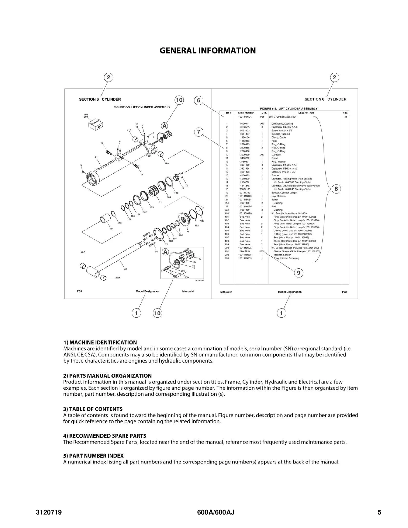
This is the full JLG 600A 600AJ Illustrated Parts Manual, published under document number 3120719 at Revision AM. It is the parts identification reference for the 600A and 600AJ boom lift series, and it spans every major assembly on the machine – from the front axle and steering installations through the turntable, boom sections, platform, hydraulic cylinders, electrical harnesses and decal sets. Each figure pairs an exploded illustration with a numbered parts table listing item number, part number, quantity and description, so any component on the machine can be traced to its correct part number before ordering.

File Details

  • Manual type: Illustrated Parts Manual
  • Brand: JLG
  • Models covered: 600A, 600AJ, N600AJ
  • Document number: 3120719
  • Revision: AM (revised January 31, 2019)
  • Original issue: February 1996 (Revision A)
  • Language: English
  • Page count: 412
  • File format: PDF

IMAGES PREVIEW

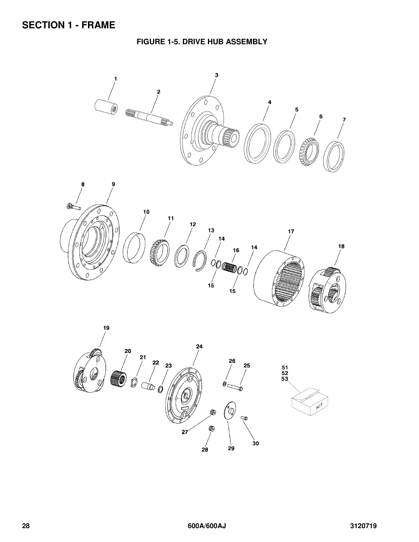
JLG 600A 600AJ Illustrated Parts Manual 3120719 Rev AM - PDF Download β€” PDF page 28 preview
JLG 600A 600AJ Illustrated Parts Manual 3120719 Rev AM - PDF Download β€” PDF page 5 preview
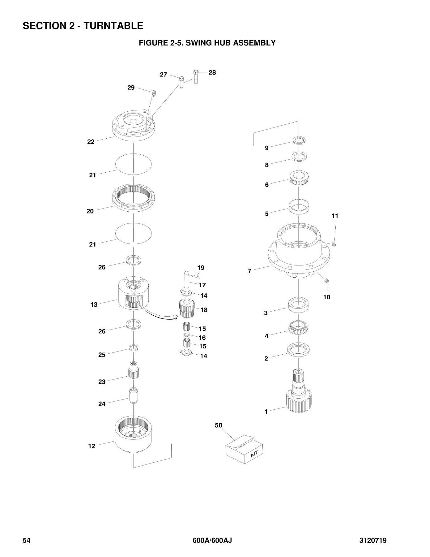
JLG 600A 600AJ Illustrated Parts Manual 3120719 Rev AM - PDF Download β€” PDF page 54 preview

Chapters Covered

  • Section 1 – Frame: 2WD front axle and steering, 4WD front axle and steering, 4WS rear steering, tire and wheel drive installations, drive hub assembly, drive brake assembly, drive motor assembly (Sundstrand 2WD and Rexroth 4WD), tow package installation
  • Section 2 – Turntable: Control valves installations, main valve block assembly, accessory valve assemblies, swing drive / turntable bearing and lock installations, swing hub, swing brake, swing motor, Continental engine installations, generator installations, Deutz engine installation with and without noise reduction, Ford engine installations (LRG-425 carbureted and EFI), dual fuel installations, Isuzu engine installation 4JB1, piston pump assembly, gear pump assembly, tanks installation, rotary coupling installations, ground control box installations (standard and ADE system), electrical options installations, engine tray jack, hoods with and without noise reduction
  • Section 3 – Boom: Booms and cylinders installation 600A, booms and cylinders installation 600AJ, tower boom assemblies, main boom assemblies, rotator assemblies (front entry and side entry platform), valves and switches installation (boom mounted), boom wipers installations
  • Section 4 – Platform: Platform components installation (front entry and side entry), platform console assembly (prior to and with ADE system), controller assembly (swing and lift), controller assembly (drive and steer), soft touch system installation
  • Section 5 – Cylinder: Axle lockout cylinder, platform level cylinder assemblies, level cylinder assembly platform slave, level (upright) cylinder assembly, lift (articulating jib) cylinder 600AJ, lift (main boom) cylinder, lift (tower boom) cylinder, master cylinder assemblies, steer cylinder assemblies, telescope (main boom) cylinder assemblies, telescope (tower boom) cylinder assembly, cylinder bellows installation
  • Section 6 – Hydraulic: Drive hydraulic diagram 2WD/2WS, drive hydraulic diagram 4WD/2WS, hydraulic diagram oscillating axle, standard hydraulic diagram, hydraulic diagram list
  • Section 7 – Electrical: Electrical diagram list, electrical schematics for diesel machines, diesel UL machines, gas machines, gas machines with EFI system, gas UL machines, UL LP-only machines, Isuzu engine machines, diesel/gas machines with ADE system, harness components installations (prior to and with ADE system)
  • Section 8 – Decals: Decals installation standard, decal installation country spec
  • Section 9 – Recommended Service Parts Stock: Models 600A / 600AJ / N600AJ standard and variable parts
  • Section 10 – Special Options: Miscellaneous special options listings
  • Part Number Index: Numerical index of all part numbers with corresponding page references

What this gives a technician is a single organized reference for identifying every serviceable component on the 600A and 600AJ. The manual is structured so that assemblies are broken down into their constituent parts, each tied to a figure number and an item callout on the illustration. Because the same assembly can change across production – the manual documents serial number breakpoints throughout – the parts tables identify which variant applies, so the correct part is selected for the machine on the shop floor rather than a superseded or incompatible one. Service replacement kits, seal kits, and complete assembly part numbers are listed alongside the individual components where they exist, which matters when a full rebuild is more practical than piece-by-piece sourcing.

Serial Number Coverage

Part listings throughout the manual are keyed to machine serial number ranges, from early production units through the 0300069000 series. The manual documents multiple break points across the frame, boom, cylinder, engine and control system sections, and where applicable an assembly is listed with “prior to” or “through” serial number notes so the correct revision is identified. Machines built from S/N 0300064249 onward incorporate the ADE (Advanced Design Electronics) System, and the manual contains distinct sections for those machines, including the ADE ground control box, platform console assembly and controller assemblies.

Complete PDF Bookmark Tree

Complete Bookmarks

The complete bookmarks in the β€œJLG 600A 600AJ Illustrated Parts Manual 3120719 Rev AM – PDF Download” are as follows:

SECTION 1 – FRAMEp. 11
FIGURE 1-1. 2WD FRONT AXLE AND STEERING INSTALLATIONSp. 12
FIGURE 1-2. 4WD FRONT AXLE AND STEERING INSTALLATIONSp. 16
FIGURE 1-3. 4WS REAR STEERING INSTALLATIONSp. 20
FIGURE 1-4. TIRE AND WHEEL DRIVE INSTALLATIONSp. 24
FIGURE 1-5. DRIVE HUB ASSEMBLYp. 28
FIGURE 1-6. DRIVE BRAKE ASSEMBLYp. 30
FIGURE 1-7. DRIVE MOTOR ASSEMBLY – SUNSTRAND (2WD)p. 34
FIGURE 1-8. DRIVE MOTOR ASSEMBLY – REXROTH (4WD)p. 36
FIGURE 1-9. TOW PACKAGE INSTALLATION (OPTIONAL)p. 38
SECTION 2 – TURNTABLEp. 41
FIGURE 2-1. CONTROL VALVES INSTALLATIONSp. 42
FIGURE 2-2. MAIN VALVE BLOCK ASSEMBLYp. 46
FIGURE 2-3. ACCESSORY VALVE ASSEMBLIESp. 50
FIGURE 2-4. SWING DRIVE, TURNTABLE BEARING AND LOCK INSTALLATIONSp. 52
FIGURE 2-5. SWING HUB ASSEMBLYp. 54
FIGURE 2-6. SWING BRAKE ASSEMBLYp. 56
FIGURE 2-7. SWING MOTOR ASSEMBLYp. 60
FIGURE 2-8. CONTINENTAL ENGINE INSTALLATIONSp. 62
FIGURE 2-9. GENERATOR INSTALLATION (OPTIONAL – CONTINENTAL ENGINE MACHINES)p. 68
FIGURE 2-10. DEUTZ ENGINE INSTALLATION – WITHOUT NOISE REDUCTION (Prior to SN 0300029930)p. 72
FIGURE 2-11. DEUTZ ENGINE INSTALLATION – WITH NOISE REDUCTION (SN 0300028190 through 030069000)p. 78
FIGURE 2-12. GENERATOR INSTALLATION (OPTIONAL – DEUTZ ENGINE MACHINES)p. 86
FIGURE 2-13. FORD ENGINE INSTALLATIONS (Prior to SN 0300037117)p. 90
FIGURE 2-14. FORD ENGINE INSTALLATIONS – LRG425 WITH CARBURETOR (SN 0300037117 through 0300069000)p. 98
FIGURE 2-15. FORD ENGINE INSTALLATIONS – LRG-425 WITH EFI (SN 0300048907 through 0300069000)p. 106
FIGURE 2-16. DUAL FUEL INSTALLATION (OPTIONAL – FORD ENGINE WITH CARBURETOR MACHINES)p. 112
FIGURE 2-17. DUAL FUEL INSTALLATION (OPTIONAL – FORD ENGINE MACHINES WITH EFI) (SN 0300048907 through 0300069000)p. 114
FIGURE 2-18. GENERATOR INSTALLATION (OPTIONAL – FORD ENGINE MACHINES)p. 116
FIGURE 2-19. ISUZU ENGINE INSTALLATION – 4JB1p. 120
FIGURE 2-20. PISTON PUMP ASSEMBLYp. 124
FIGURE 2-21. GEAR PUMP ASSEMBLYp. 130
FIGURE 2-22. TANKS INSTALLATIONp. 132
FIGURE 2-23. ROTARY COUPLING INSTALLATIONSp. 136
FIGURE 2-24. GROUND CONTROL BOX INSTALLATIONS (Prior to SN 0300064249)p. 138
FIGURE 2-25. GROUND CONTROL BOX INSTALLATIONS (ADE SYSTEM) (SN 0300064249 through 0300069000)p. 144
FIGURE 2-26. ELECTRICAL OPTIONS INSTALLATIONS (TURNTABLE MOUNTED)p. 148
FIGURE 2-27. ENGINE TRAY JACK INSTALLATIONS (OPTIONAL)p. 152
FIGURE 2-28. HOODS INSTALLATIONS – WITHOUT NOISE REDUCTIONp. 154
FIGURE 2-29. HOODS INSTALLATIONS – WITH NOISE REDUCTIONp. 158
SECTION 3 – BOOMp. 163
FIGURE 3-1. BOOMS AND CYLINDERS INSTALLATION – 600Ap. 164
FIGURE 3-2. BOOMS AND CYLINDERS INSTALLATION – 600AJp. 168
FIGURE 3-3. TOWER BOOM ASSEMBLIESp. 174
FIGURE 3-4. MAIN BOOM ASSEMBLIESp. 178
FIGURE 3-5. ROTATOR ASSEMBLIES (FRONT ENTRY PLATFORM)p. 182
FIGURE 3-6. ROTATOR ASSEMBLIES (SIDE ENTRY PLATFORM)p. 186
FIGURE 3-7. VALVES AND SWITCHES INSTALLATION (BOOM MOUNTED)p. 188
FIGURE 3-8. BOOM WIPERS INSTALLATIONS (OPTIONAL)p. 190
SECTION 4 – PLATFORMp. 193
FIGURE 4-1. PLATFORM COMPONENTS INSTALLATION (FRONT ENTRY)p. 194
FIGURE 4-2. PLATFORM COMPONENTS INSTALLATION (SIDE ENTRY)p. 198
FIGURE 4-3. PLATFORM CONSOLE ASSEMBLY (Prior to SN 0300064249)p. 202
FIGURE 4-4. PLATFORM CONSOLE ASSEMBLY (WITH ADE SYSTEM) (SN 0300064249 through 0300069000)p. 208
FIGURE 4-5. CONTROLLER ASSEMBLY (SWING AND LIFT) (Prior to SN 0300039749)p. 212
FIGURE 4-6. CONTROLLER ASSEMBLY (SWING AND LIFT) (SN 0300039749 through 0300064249)p. 214
FIGURE 4-7. CONTROLLER ASSEMBLY (SWING AND LIFT) (WITH ADE SYSTEM) (ORIGINAL EQUIPMENT) (SN 0300064249 through 0300069000)p. 216
FIGURE 4-8. CONTROLLER ASSEMBLY (SWING AND LIFT) (WITH ADE SYSTEM) (SERVICE REPLACEMENT) (SN 0300064249 through 0300069000)p. 218
FIGURE 4-9. CONTROLLER ASSEMBLY (SWING AND LIFT) (WITH ADE SYSTEM) (SERVICE REPLACEMENT) (SN 0300064249 through 0300069000)p. 220
FIGURE 4-10. CONTROLLER ASSEMBLY (DRIVE AND STEER) (Prior to SN 0300039749)p. 224
FIGURE 4-11. CONTROLLER ASSEMBLY (DRIVE AND STEER) (SN 0300039749 through 0300064249)p. 228
FIGURE 4-12. CONTROLLER ASSEMBLY (DRIVE AND STEER) (WITH ADE SYSTEM) (ORIGINAL EQUIPMENT) (SN 0300064249 through 0300069000)p. 230
FIGURE 4-13. CONTROLLER ASSEMBLY (DRIVE AND STEER) (WITH ADE SYSTEM) (SERVICE REPLACEMENT) (SN 0300064249 through 0300069000)p. 232
FIGURE 4-14. CONTROLLER ASSEMBLY (DRIVE AND STEER) (WITH ADE SYSTEM) (SERVICE REPLACEMENT) (SN 0300064249 through 0300069000)p. 234
FIGURE 4-15. SOFT TOUCH SYSTEM INSTALLATION (OPTIONAL) (SN 0300039749 through 0300064249)p. 236
SECTION 5 – CYLINDERp. 239
FIGURE 5-1. AXLE LOCKOUT CYLINDER ASSEMBLYp. 240
FIGURE 5-2. PLATFORM LEVEL CYLINDER ASSEMBLIES (Prior to SN 0300024714)p. 242
FIGURE 5-3. PLATFORM LEVEL CYLINDER ASSEMBLIES (ORIGINAL EQUIPMENT) (SN 0300024714 through 0300069000)p. 244
FIGURE 5-4. LEVEL CYLINDER ASSEMBLY – PLATFORM SLAVE (600A) (SERVICE REPLACEMENT)p. 248
FIGURE 5-5. LEVEL CYLINDER ASSEMBLY – PLATFORM SLAVE (600AJ) (SERVICE REPLACEMENT)p. 250
FIGURE 5-6. LEVEL (UPRIGHT) CYLINDER ASSEMBLYp. 252
FIGURE 5-7. LEVEL CYLINDER ASSEMBLY- UPRIGHT (SERVICE REPLACEMENT)p. 254
FIGURE 5-8. LIFT (ARTICULATING JIB) CYLINDER ASSEMBLY – 600AJp. 256
FIGURE 5-9. LIFT (MAIN BOOM) CYLINDER ASSEMBLY (ORIGINAL EQUIPMENT)p. 258
FIGURE 5-10. LIFT CYLINDER ASSEMBLY – MAIN BOOM (SERVICE REPLACEMENT)p. 260
FIGURE 5-11. LIFT (TOWER BOOM) CYLINDER ASSEMBLY (ORIGINAL EQUIPMENT)p. 262
FIGURE 5-12. LIFT CYLINDER ASSEMBLY – TOWER BOOM (SERVICE REPLACEMENT)p. 264
FIGURE 5-13. MASTER CYLINDER ASSEMBLIES (ORIGINAL EQUIPMENT)p. 266
FIGURE 5-14. MASTER CYLINDER ASSEMBLY – 600A (SERVICE REPLACEMENT)p. 270
FIGURE 5-15. MASTER CYLINDER ASSEMBLY – 600AJ (SERVICE REPLACEMENT)p. 272
FIGURE 5-16. STEER CYLINDER ASSEMBLIESp. 274
FIGURE 5-17. TELESCOPE (MAIN BOOM) CYLINDER ASSEMBLIES (ORIGINAL EQUIPMENT)p. 276
FIGURE 5-18. TELESCOPE CYLINDER ASSEMBLY – MAIN BOOM (600A) (SERVICE REPLACEMENT)p. 278
FIGURE 5-19. TELESCOPE CYLINDER ASSEMBLY – MAIN BOOM (600AJ) (SERVICE REPLACEMENT)p. 280
FIGURE 5-20. TELESCOPE (TOWER BOOM) CYLINDER ASSEMBLY (ORIGINAL EQUIPMENT)p. 282
FIGURE 5-21. TELESCOPE CYLINDER ASSEMBLY – TOWER BOOM (SERVICE REPLACEMENT)p. 284
FIGURE 5-22. CYLINDER BELLOWS INSTALLATION (OPTIONAL)p. 286
SECTION 6 – HYDRAULICp. 289
FIGURE 6-1. DRIVE HYDRAULIC DIAGRAM – 2WD/2WSp. 290
FIGURE 6-2. DRIVE HYDRAULIC DIAGRAM – 4WD/2WSp. 292
FIGURE 6-3. HYDRAULIC DIAGRAM – OSCILLATING AXLEp. 296
FIGURE 6-4. HYDRAULIC DIAGRAM – STANDARDp. 298
FIGURE 6-5. HYDRAULIC DIAGRAM LISTp. 302
SECTION 7 – ELECTRICALp. 303
FIGURE 7-1. ELECTRICAL DIAGRAM LISTp. 304
FIGURE 7-2. ELECTRICAL SCHEMATIC – DIESEL MACHINES WITH COLORED WIRING (Prior to SN 0300035129)p. 308
FIGURE 7-3. ELECTRICAL SCHEMATIC – DIESEL MACHINES WITH NUMBERED COLORED WIRING (SN 0300035129 through 0300069000)p. 312
FIGURE 7-4. ELECTRICAL SCHEMATIC – DIESEL UL MACHINES WITH NUMBERED COLORED WIRING (SN 0300039457 through 0300069000)p. 316
FIGURE 7-5. ELECTRICAL SCHEMATIC – GAS MACHINES WITH COLORED WIRING (Prior to SN 0300035129)p. 320
FIGURE 7-6. ELECTRICAL SCHEMATIC – GAS MACHINES WITH NUMBERED COLORED WIRING (SN 0300035129 through 0300048907)p. 324
FIGURE 7-7. ELECTRICAL SCHEMATIC – GAS MACHINES WITH EFI SYSTEM (SN 0300048907 through 0300069000)p. 328
FIGURE 7-8. ELECTRICAL SCHEMATIC – GAS UL MACHINES WITH NUMBERED COLORED WIRING (SN 0300039457 through 0300069000)p. 332
FIGURE 7-9. ELECTRICAL SCHEMATIC – UL MACHINES (LP ONLY WITH NUMBERED COLORED WIRING (SN 0300039457 through 0300069000)p. 336
FIGURE 7-10. ELECTRICAL SCHEMATIC – ISUZU ENGINE (SN 0300063908 through 0300069000)p. 340
FIGURE 7-11. ELECTRICAL SCHEMATIC – DIESEL/GAS MACHINES (WITH ADE SYSTEM) (SN 0300064249 through 0300069000)p. 344
FIGURE 7-12. HARNESS COMPONENTS INSTALLATION (Prior to SN 0300064249)p. 348
FIGURE 7-13. HARNESS COMPONENTS INSTALLATION (WITH ADE SYSTEM) (SN 0300064249 through 0300064269)p. 360
FIGURE 7-14. HARNESS COMPONENTS INSTALLATION (WITH ADE SYSTEM) (SN 0300064270 through 0300069000)p. 368
SECTION 8 – DECALSp. 377
FIGURE 8-1. DECALS INSTALLATION – STANDARDp. 378
FIGURE 8-2. DECAL INSTALLATION – COUNTRY SPECp. 382
SECTION 9 – RECOMMENDED SERVICE PARTS STOCKp. 387
FIGURE 9-1. MODELS 600A/600AJ/N600AJp. 388
FIGURE 9-2. MODELS 600A/600AJ/N600AJp. 390
SECTION 10 – SPECIAL OPTIONSp. 391
FIGURE 10-1. SPECIAL OPTIONSp. 392
PART NUMBER INDEXp. 397

Engine and Powertrain Variants Documented

  • Continental TMD-27 diesel engine installation
  • Deutz F4M1011F diesel engine installations, with and without noise reduction
  • Ford LRG-423 engine installations
  • Ford LRG-425 engine installations with carburetor
  • Ford LRG-425 engine installations with EFI
  • Isuzu 4JB1 engine installation
  • Dual fuel installations for Ford engine machines with carburetor and with EFI

Each engine section covers the engine mounting hardware, radiator and cooling components, air cleaner, exhaust and muffler, oil drain, battery and cable kits, throttle actuator and governor components, and the engine-side accessories. Generator installations for 110V and 220V systems are broken down by engine variant and serial range, including control box, receptacle and breaker components.

Hydraulic, Electrical and Cylinder Content

The hydraulic diagrams section covers the drive circuits for 2WD/2WS and 4WD/2WS, the oscillating axle circuit and the standard machine circuit, with every fitting, hose and valve called out by part number. The electrical section includes wiring schematics for diesel, gas, EFI, UL and LP-only machines, plus the ADE system schematics, and the harness components installation figures break down the platform box harness, boom cables, ground control box harness, engine harness and valve harness by connector, socket, pin and seal. Section 5 covers every hydraulic cylinder on the machine – axle lockout, platform level, slave, upright level, articulating jib, main lift, tower lift, master, steer, main telescope and tower telescope – with barrel, rod, head, piston, bushing, cartridge valve and seal kit part numbers, including original equipment and service replacement versions.

Why This Parts Manual Matters

Ordering the wrong part on a boom lift is expensive in both money and downtime. The JLG 600A 600AJ Illustrated Parts Manual 3120719 gives you the figure numbers, item callouts and part numbers that let you confirm exactly which component belongs to your machine before the order goes out. Every figure is tied to the machine’s serial number breaks and engine configuration, so a part for an early 600A with a Continental engine is not confused with the equivalent position on a later 600AJ with a Deutz or Ford EFI engine. Seal kit and repair kit part numbers are included where the manufacturer packages components together, and the recommended service parts stock section tells you which items are worth keeping on the shelf for field repairs.

Instant PDF Delivery

The manual is delivered as an instant PDF download after checkout – no shipping, no waiting on a physical book. Once downloaded, the file is yours to keep. It can be opened on a laptop, tablet or phone in the shop, printed as individual pages for the job at hand, or printed in full for the service library. Search and navigation work the same way as any other PDF document on your device, so you can jump straight to the figure or part number you need.
Reviews

There are no reviews yet.

Be the first to review “JLG 600A 600AJ Illustrated Parts Manual 3120719 Rev AM – PDF Download”

What Our Customers Say

β˜…β˜…β˜…β˜…β˜… Live reviews from customers
Loading customer reviews...
0
    0
    Your Cart
    Your cart is emptyReturn to Shop
    πŸ›’
    Recently Purchased
    πŸ•’ verified order