
Sany Excavator Engine Parts Manual – Engine 160102070215A PDF Spare Parts Catalog
Original price was: $34.95.$19.95Current price is: $19.95.
Illustrated Sany parts manual for engine assembly 160102070215A – 70 exploded-view groups, part numbers, descriptions and quantities across 312 pages, delivered as an instant PDF download.
Description
Sany Excavator Engine Parts Manual
The Sany Excavator Engine Parts Manual for engine assembly 160102070215A is the illustrated spare-parts catalogue used to identify and order replaceable components on this specific Sany engine. Every group in the book pairs a drawing with a numbered parts table, so a callout on the illustration leads straight to a part number, a description and the quantity required. If you are rebuilding, resealing or simply replacing a failed component on a Sany machine running the 160102070215A engine, this is the document that tells you which number to quote.
File Details
- Manual type: Illustrated Parts Manual
- Brand: Sany
- Engine covered: 160102070215A
- Language: English
- Page count: 312 pages
- File format: PDF
- Parts groups: 70 illustrated group listings
- Reference system: Index, part number, description, quantity and see-page columns
- Back matter: Alphabetical part-number index
Chapters Covered
The contents are organised as 70 numbered groups, each one a self-contained assembly with its own illustration and parts table:
- Group 1 – Engine
- Group 2 – Oil Fill Labeling
- Group 3 – Engine Oil
- Group 4 – Front Gear Chamber (Dummy)
- Group 5 – Crankcase Respirator Line
- Group 6 – Crankcase Breather
- Group 7 – Compressor Coolant Pipeline
- Group 8 – Coolant Heater Starting Auxiliary Device
- Group 9 – Damping Pad
- Group 10 – Thermostat
- Group 11 – Rear Gear Train Accessories Mounting Parts
- Group 12 – Engine Grounding Mount
- Group 13 – Thermostat
- Group 14 – Charger
- Group 15 – Alternator Mounting
- Group 16 – Fan Drive Mounting
- Group 17 – Fan Drive Device
- Group 18 – Fuel Drain Plumbing
- Group 19 – Fuel Filter Position
- Group 20 – Oil Level Sensor
- Group 21 – Flywheel Housing Mounting
- Group 22 – Flywheel Case
- Group 23 – Flywheel Shell Pipeline
- Group 24 – Fuel Inlet Pipe Joint
- Group 25 – Fuel Pump
- Group 26 – Fuel Line
- Group 27 – Flywheel Mount
- Group 28 – Flywheel
- Group 29 – Front Gear Chamber Cover
- Group 30 – Cab Heater Line
- Group 31 – Auxiliary Pump Mounting
- Group 32 – Auxiliary Cooling Line
- Group 33 – Intake Joint
- Group 34 – Intake Manifold
- Group 35 – Intake Manifold Mounts
- Group 36 – Air Conveyor Connector
- Group 37 – Lifting Lug Mounting Parts
- Group 38 – Lifting Equipment Layout Diagram
- Group 39 – Engine Oil Cooler
- Group 40 – Full Flow Oil Filter
- Group 41 – Oil Gauge
- Group 42 – Lubrication Pump
- Group 43 – Oil Filling Device
- Group 44 – Oil Pan
- Group 45 – Accessory Drive Pulley
- Group 46 – Exhaust Outlet Connector
- Group 47 – Engine Control Module
- Group 48 – Performance Parts
- Group 49 – Injector Line
- Group 50 – Torque Converter Oil Cooler
- Group 51 – Engine Piston
- Group 52 – Remote Oil Back To Youtube
- Group 53 – Rocker Arm
- Group 54 – Engine Coolant Exhaust Pipe
- Group 55 – Heat Shield
- Group 56 – Starter Motor Mounting
- Group 57 – Fan Guide Device Bushing
- Group 58 – Starter Motor
- Group 59 – Exhaust Manifold
- Group 60 – Exhaust Manifold Mounts
- Group 61 – Turbocharger Line
- Group 62 – Valve Chamber Cover Arrangement Diagram
- Group 63 – Water Inlet Joint
- Group 64 – Outlet Connector
- Group 65 – Water Pump Drive
- Group 66 – Belt Tensioner
- Group 67 – Water Pump
- Group 68 – Electronic Control Module Wire Harness
- Group 69 – Conductor Holder
- Group 70 – Wire
Taken together, those groups cover the whole engine as a serviceable assembly: the block and its mounting hardware, the front and rear gear trains, the lubrication circuit from pan and suction pipe through the oil cooler and full-flow filter to the lubrication pump, the cooling circuit from water pump and thermostat through the inlet joint and outlet connector, the fuel path from inlet pipe joint and filter position through the fuel pump to the injector lines and accumulator, and the air side from intake joint and manifold through the turbocharger lines to the exhaust manifold and outlet. Electrical and electronic content is not skimped either – the engine control module group, the electronic control module wire harness, the conductor holder and the wiring group each carry their own illustrated breakdown, alongside the starter motor, alternator mounting and charger groups.
How the Parts Tables Are Organised
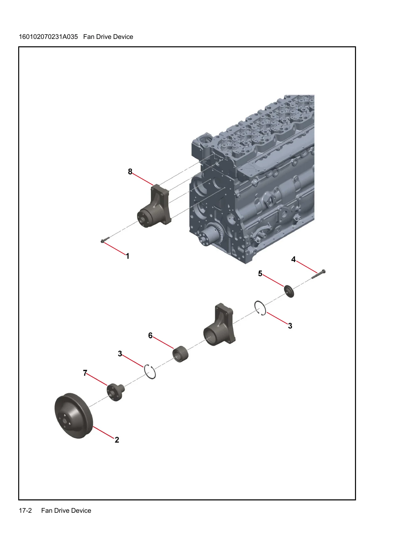
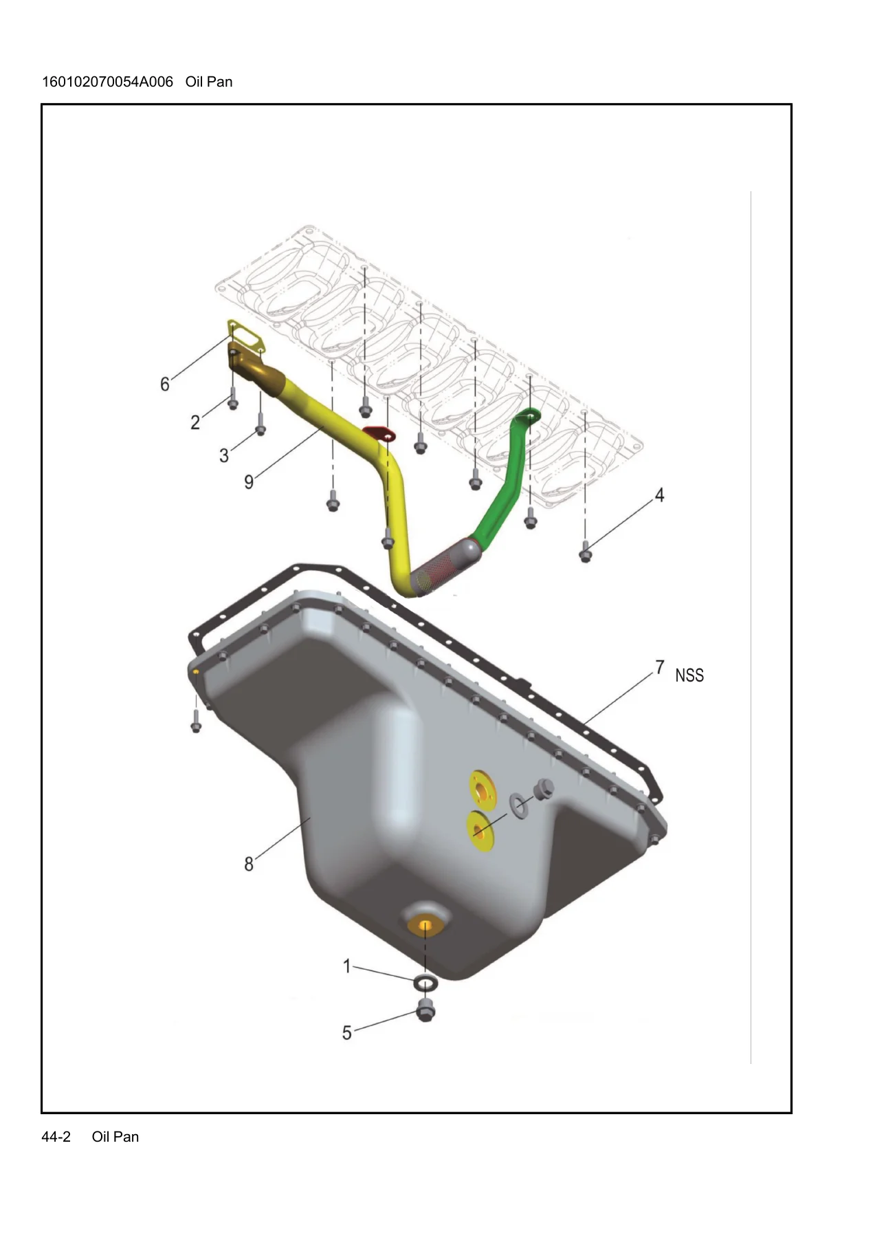
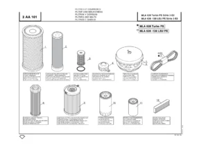
Every group follows the same logic, which is what makes the Sany 160102070215A engine parts manual practical at the bench. An illustration comes first, drawn in line art or as a rendered assembly, with each individual component tagged by a callout number. The table beneath it carries an INDEX column matching those callouts, a PART NO. column carrying the exact number to quote, a DESCRIPTION column naming the item, a Remark column where needed, and a QTY column stating how many are required per assembly. A SEE PAGE reference points back to the group location in the engine-level listing, so you can move from a single bolt up to the assembly it belongs to without guessing.
Because the quantities are stated per group, the manual also doubles as a reseal and rebuild checklist. Before a gasket, seal, O-ring or fastener goes back on, you can confirm from the table whether it is listed once or several times in that assembly, which is the difference between ordering one sealing washer and ordering six.
Illustrations and Exploded Views
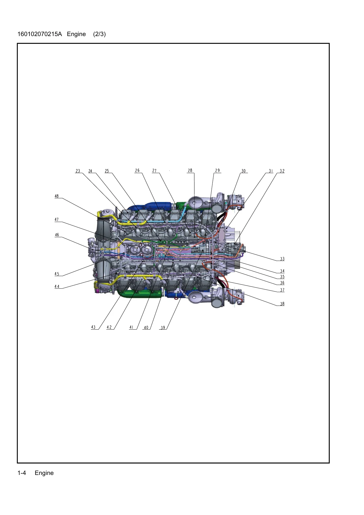
The engine overview plates at the front of the manual show the complete 160102070215A unit with callout numbers across several views, giving an at-a-glance map of where each group sits on the engine. From there the illustrations become progressively more specific – the front gear chamber and its cover, the fan drive device with its pulley, retaining rings, hub retainer and bearings, the flywheel and flywheel case with their seals and plugs, the oil pan with its drainer O-ring and suction pipe connector, the rocker arm assembly with its push rods, brackets, shafts and adjusting screws, the piston and connecting rod set, and the turbocharger line with its hoses, banjo connectors, sealing washers and O-rings. Cooling, fuel, intake and exhaust plumbing are all drawn as pipework rather than plain lists, so routing and joint hardware are visible rather than implied.
Parts Coverage at a Glance
Common wear and service items appear repeatedly across the groups: sealing washers, O-rings, gaskets, hexagon flange bolts, threaded plugs, hose clamps, flexible hoses and pipe joints. Major assemblies are broken down far enough to be useful rather than merely indicative – the water pump group lists the pump and its rectangular sealing ring, the belt tensioner group lists the tension pulley belt and its retaining bolt, the fuel pump group lists the pump, its gear, double end stud, hex nut and spring washer, and the thermostat groups list both the thermostat assembly and its seals. The performance parts group reaches into the cylinder head itself with valves, valve springs, valve spring seats, valve rod seals, valve seat rings, collets, camshaft, camshaft support and cylinder head, and the engine control module group itemises sensors, connectors, mounting brackets, vibration damping pads and the ground wire.
Why the Part Number Matters
Sany engines are assembled from a large number of visually similar fasteners, seals and fittings, and two components that look identical on the bench can carry different part numbers and different specifications. Ordering from a photograph or a description alone is how wrong parts arrive. Working from the illustrated group listing lets you identify the exact index number on the exact assembly, read the part number and the quantity, and quote it correctly. That is the entire purpose of this manual, and it is why the alphabetical part-number index at the back is as useful as the group pages themselves – if you already have a number, you can confirm what it is and where it goes.
Order the Sany Engine 160102070215A Parts Manual
With this parts manual on hand you can identify and order replacement components for the 160102070215A engine across all 70 groups – front and rear gear train hardware, lubrication and oil cooler parts, cooling system joints, fuel supply and injector line components, intake and exhaust plumbing, turbocharger lines, flywheel and housing parts, rocker arm and valve train items, piston and connecting rod parts, starter, alternator and fan drive components, and the full engine control module and wiring breakdown. Correct part numbers and correct quantities mean fewer wrong orders, shorter machine downtime and a rebuild that goes back together the way it left the factory.
The manual is delivered as an instant PDF download – no shipping, no waiting for a parcel, and no risk of a paper copy going missing in the workshop. Open it on a laptop, tablet or phone at the machine, print the group pages you are working from, and keep the rest of the catalogue to hand for the next job.
Reviews
There are no reviews yet.