★ TRUSTED BY 321,897+ PROFESSIONALS WORLDWIDE
🏒
Trusted Business
Verified & Licensed
πŸ›‘οΈ
Virus Free Files
100% Safe Downloads
πŸ”’
Secure Payment
SSL Protected
⚑
Instant Delivery
Available Immediately
Sale!

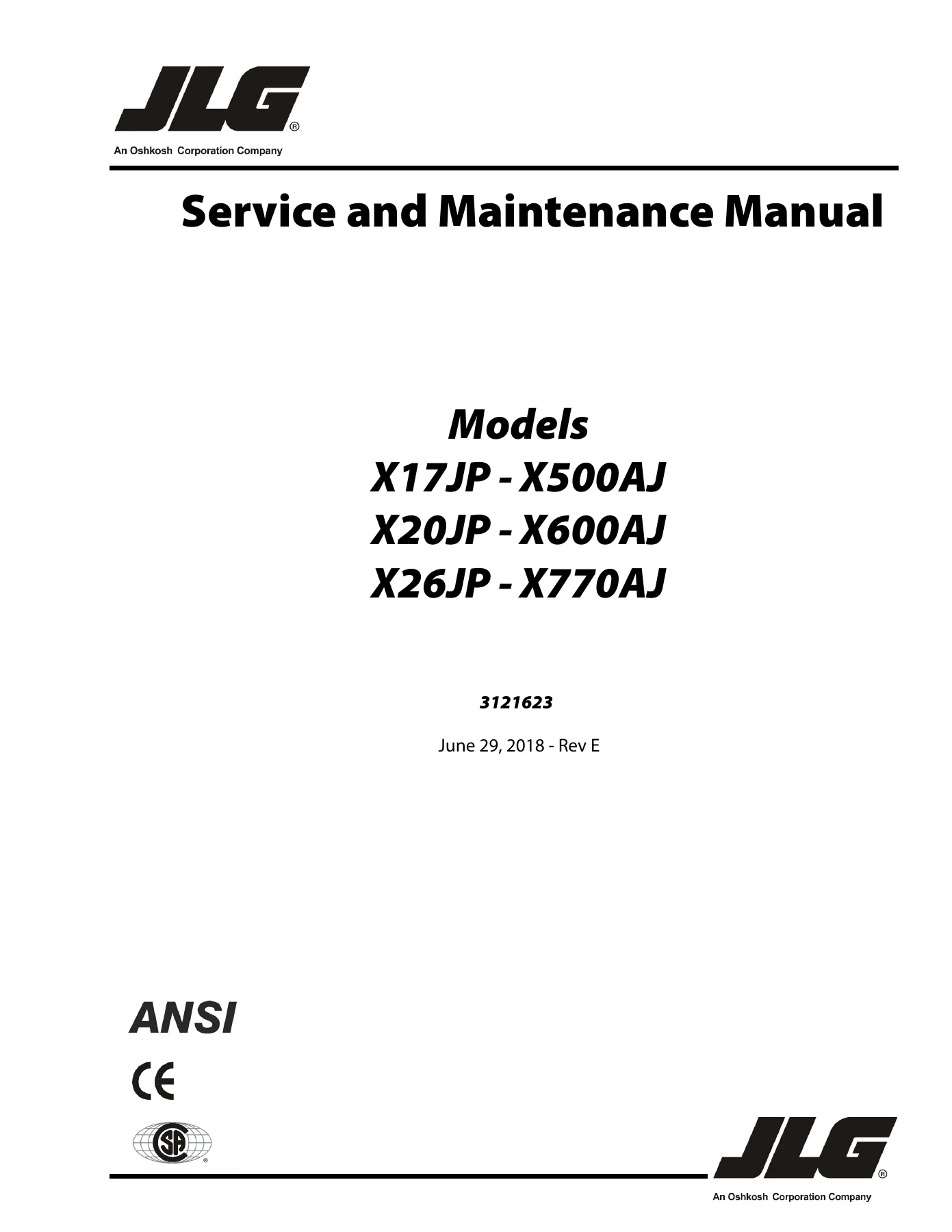
JLG X17JP X500AJ X20JP X600AJ X26JP X770AJ Service and Maintenance Manual 3121623 Rev E 2018

Original price was: $39.95.Current price is: $24.95.

Complete JLG Service and Maintenance Manual for X17JP, X500AJ, X20JP, X600AJ, X26JP and X770AJ compact crawler boom lifts. Document 3121623 Rev E, June 29, 2018. Covers chassis, turntable, boom, hydraulics, engines, JLG control system, schematics, torque and pressure specifications. Instant PDF download.

⚑
Instant PDF Download
Available immediately
πŸ’Ύ
Save to Your Device
Download & keep forever
πŸ›‘οΈ
Antivirus Scanned
100% virus-free
🌍
Trusted Worldwide
175,000+ customers

Description

JLG X17JP X500AJ X20JP X600AJ X26JP X770AJ Service and Maintenance Manual – Document 3121623 Rev E

This is the full JLG X17JP X500AJ X20JP X600AJ X26JP X770AJ Service and Maintenance Manual, released under document number 3121623 at Revision E dated June 29, 2018. It covers six compact crawler boom lift models across CE and ANSI configurations and is written for the qualified JLG equipment mechanic and factory-certified service technician who is responsible for placing the machine into operation readiness and keeping it in a safe operating condition. Rather than a short operator booklet, this is the complete workshop reference: capacities, torque charts, pressure settings, component weights, hydraulic schematics, cylinder repair procedures, engine diagnostics, CANBUS troubleshooting, SkyGuard installation, and the full service menu tree of the JLG Control System.

File Details

  • Manual type: Service and Maintenance Manual
  • Brand: JLG Industries, Inc.
  • Document number: 3121623
  • Revision: Rev E – June 29, 2018
  • Revision history: Original Issue A (Oct 21, 2013), Rev B (Nov 3, 2016), Rev C (Mar 29, 2017), Rev D (Mar 27, 2018), Rev E (Jun 29, 2018 – Revised Covers)
  • Language: English
  • Format: PDF (digital download)
  • Sections: Section 1 Specifications Β· Section 2 General Β· Section 3 Chassis & Turntable Β· Section 4 Boom & Platform Β· Section 5 Hydraulics Β· Section 6 JLG Control System Β· Section 7 General Electrical Information & Schematics

Chapters Covered

The JLG X17JP X500AJ X20JP X600AJ X26JP X770AJ service manual is organized into seven top-level sections with detailed sub-sections. The main content areas are:

IMAGES PREVIEW

JLG X17JP X500AJ X20JP X600AJ X26JP X770AJ Service and Maintenance Manual 3121623 Rev E 2018 β€” PDF page 1 preview
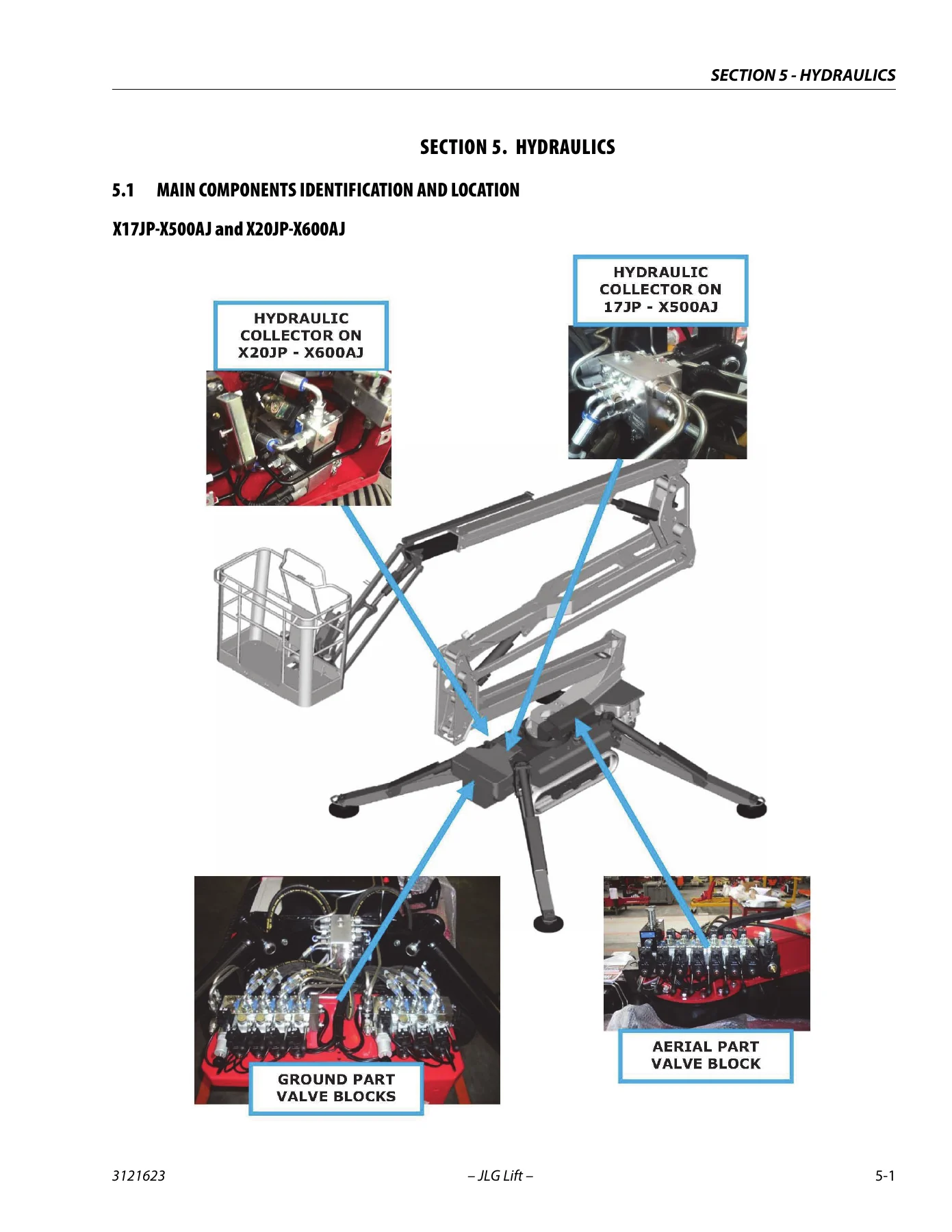
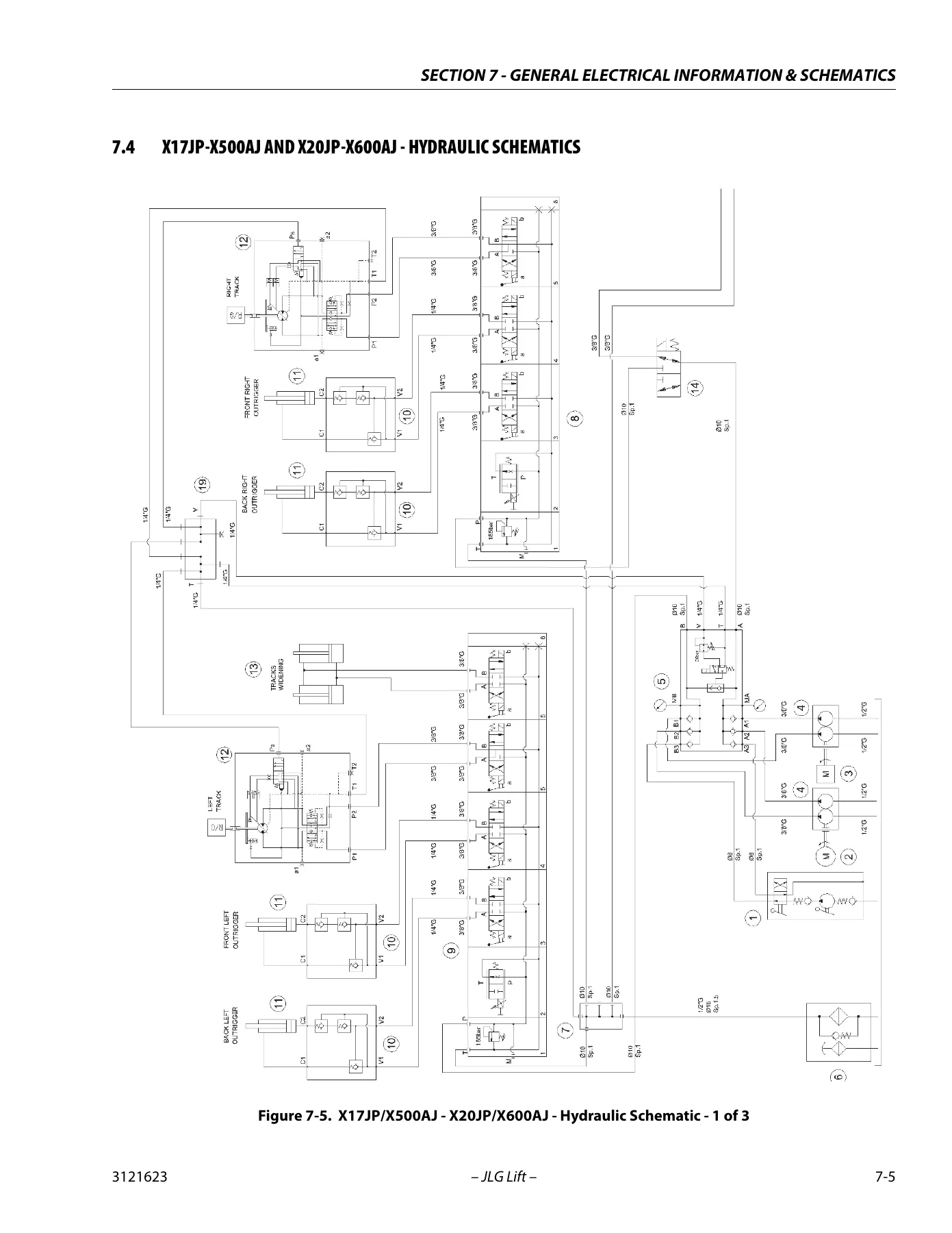
JLG X17JP X500AJ X20JP X600AJ X26JP X770AJ Service and Maintenance Manual 3121623 Rev E 2018 β€” PDF page 111 preview
JLG X17JP X500AJ X20JP X600AJ X26JP X770AJ Service and Maintenance Manual 3121623 Rev E 2018 β€” PDF page 245 preview

  • Section 1 – Specifications: Capacities, track specifications, ground bearing pressure, power source configurations, Honda iGX390 / iGX440 / Hatz 1B40 / Perkins 402D / Kubota D902-E3B engine specifications, reach specifications, dimensional data, function speed data, hydraulic pressure settings, major component weights, lubrication, hydraulic oil temperature range, serial number locations, fastener torque charts (SAG, SAE and metric).
  • Section 2 – General: Machine preparation, inspection and maintenance, pre-start / pre-delivery / frequent / annual inspection responsibilities, service and workmanship guidelines, cleanliness, component removal and installation, pressure-fit parts, bearings, gaskets, bolt usage and torque, hydraulic lines and electrical wiring, hydraulic system care, lubrication specifications, cylinder drift test, pins and composite bearing repair, welding on JLG equipment.
  • Section 3 – Chassis & Turntable: Rubber track maintenance (tension checking, loosening/tightening, replacement), undercarriage components, roller lower wheel and track adjuster replacement, sprocket and gear motor removal and installation, final drive torque values, axle extension removal, Bonfiglioli final drive identification, IMO swing drive technical data, transport, positioning and bolting, maintenance schedule and lubrication, Honda iGX440 engine, Hatz 1B40 engine, Perkins 402D engine, Kubota D902 diesel engine, speed sensor installation and adjustment, diesel RPM control, thermic engine replacement, electric motor replacement.
  • Section 4 – Boom & Platform: Boom maintenance, removal and disassembly of the main boom, boom disassembly for X20JP / X600AJ, inspection of ropes and pulleys, wire rope tension adjustment procedure, Moveco ARP series rotary actuator technical data, disassembly and assembly, counterbalance valve installation, boom rotation sensor assembly for X26JP / X770AJ, proximity sensor adjustment for X17JP / X500AJ / X20JP / X600AJ, platform removal and installation, load cell and footswitch removal and installation, SkyGuard installation for one-person and two-person platforms, SkyGuard anti-trapping system function tables and schematics.
  • Section 5 – Hydraulics: Main components identification and location, hydraulic system pump and pressure lines, ground component hydraulic system, outriggers, drive gear motors, tracks widening, boom component hydraulic system (first and second booms, third boom, telescope, jib, basket levelling, basket rotation, turret rotation, emergency gravity descent system), cylinder repair specifications, cylinder disassembly and assembly with and without sensor, magnetic sensor removal, threaded piston disassembly, seals head replacing, cylinder inspection, bushing replacement, cylinders bleeding, replacement hydraulic pump, hydraulic pump repair with seal kit, hydraulic component start-up procedures and recommendations, pressure setting procedure for chassis and turntable functions, outriggers auto-retraction.
  • Section 6 – JLG Control System: Introduction, machine ignition, platform remote control station, LCD display screen and icon descriptions, joystick controls, tilt conditions drive cut-out, speed control conditions per model, push buttons, CANBUS communications, CAN bus device positions and layout, CAN diagnostics and CAN timeout menu, software check, sensors and devices not communicating through CAN-BUS, inclination sensor system, load cell system, rotation sensor system, electric motor, 12 V battery, battery charge system, calibration requirements, platform remote control service, service menu (INPUT/OUTPUT, LANGUAGE, ERRORS, RAMP, CURRENT, WORKING HOURS, SETUP, JOYSTICK), machine setup menus 1 through 7 including tilt sensor calibration, version and engine type, machine configuration, swing sensor calibration (X26JP / X770AJ), load sensing system calibration, time and date setup, joystick calibration.
  • Section 7 – General Electrical Information & Schematics: General electrical information, multimeter basics (grounding, backprobing, Min/Max, polarity, scale, voltage/resistance/continuity/current measurement), continuity measurement over long distances, electrical schematics manuals list, X17JP / X500AJ and X20JP / X600AJ hydraulic schematics, X26JP / X770AJ hydraulic schematics.

Taken as a whole, this document is a complete service-bay reference for the six-model compact crawler boom lift family. It pairs the fast-access data a mechanic needs in the first five minutes of a job (capacities, torque charts, pressure settings, component weights) with the step-by-step repair procedures needed when a component actually comes apart β€” cylinder resealing, sprocket and gear motor removal, boom disassembly, rotary actuator overhaul, pump seal replacement. Diagnostic material is equally developed: engine LED flash codes for the Honda iGX, harness by-pass procedures for Honda, Hatz, Perkins and Kubota diesel engines, the input/output menu tree for reading live switch and sensor states, and the full CAN timeout table for chasing intermittent CANBUS faults.

Covered Models and Power Sources

The JLG 3121623 service manual covers three base machines β€” X17JP / X500AJ, X20JP / X600AJ and X26JP / X770AJ β€” in both CE (JP) and ANSI (AJ) designations. Engine coverage spans the following:

Complete PDF Bookmark Tree

Complete Bookmarks

The complete bookmarks in the β€œJLG X17JP X500AJ X20JP X600AJ X26JP X770AJ Service and Maintenance Manual 3121623 Rev E 2018” are as follows:

INTRODUCTION – MAINTENANCE SAFETY PRECAUTIONSp. 3
Generalp. 3
Hydraulic System Safetyp. 3
Maintenancep. 3
Section 1. SPECIFICATIONSp. 11
1.1 Capacitiesp. 11
1.2 Track specificationsp. 12
1.3 POWER SOURCEp. 13
Honda Engine iGX390 Specificationsp. 14
Honda Engine iGX440 Specificationsp. 14
Hatz Engine 1B40 Specificationsp. 15
Perkins Engine 402D Specificationsp. 15
Kubota Engine D902-E3B Specificationsp. 16
1.4 Specifications and Performance Datap. 17
Reach Specificationsp. 17
Dimensional Datap. 17
Function Speed Datap. 18
Machine Orientation When Performing Speed Testsp. 18
1.5 Hydraulic PRESSURE SETTINGS – PSI (BAR)p. 19
1.6 Major Component Weightsp. 19
1.7 Lubricationp. 20
Hydraulic Oilp. 20
1.8 SERIAL NUMBER LOCATIONp. 21
1.9 Fastener Torque Chartsp. 22
Section 2. GENERALp. 27
2.1 Machine Preparation, Inspection, and Maintenancep. 27
Generalp. 27
Preparation, Inspection, and Maintenancep. 27
Pre-Start Inspectionp. 27
Pre-Delivery Inspection and Frequent Inspectionp. 27
Annual Machine Inspectionp. 27
Preventative Maintenancep. 27
2.2 Service and Guidelinesp. 28
Generalp. 28
Safety and Workmanshipp. 28
Cleanlinessp. 28
Components Removal and Installationp. 28
Component Disassembly and Reassemblyp. 28
Pressure-Fit Partsp. 28
Bearingsp. 29
Gasketsp. 29
Bolt Usage and Torque Applicationp. 29
Hydraulic Lines and Electrical Wiringp. 29
Hydraulic Systemp. 29
Lubricationp. 29
Batteryp. 29
Lubrication and Servicingp. 29
2.3 Lubrication and Informationp. 29
Hydraulic Systemp. 29
Hydraulic Oilp. 30
Changing Hydraulic Oilp. 30
Lubrication Specificationsp. 30
2.4 Cylinder Drift Testp. 30
Cylinder Driftp. 30
2.5 Pins and Composite Bearing Repair Guidelinesp. 31
2.6 Welding on JLG Equipmentp. 31
Do the Following When Welding on JLG Equipmentp. 31
Do NOT Do the Following When Welding on JLG Equipmentp. 31
Section 3. CHASSIS & TURNTABLEp. 33
3.1 RUBBER TRACK MAINTENANCEp. 33
Checking Track Tensionp. 33
Operations For Loosening/tightening The Trackp. 33
Checking The Rubber Tracksp. 34
Replacing The Rubber Tracksp. 35
Installing The Rubber Trackp. 35
Checking tightness of nuts and boltsp. 36
3.2 UNDERCARRIGE COMPONENTSp. 36
Replacement roller lower wheel and tracks adjusterp. 36
Disassemblyp. 36
Assemblyp. 36
Replacement sprocket and Gear Motorp. 37
Sprocket removep. 37
Gear motor removep. 37
Gear motor installationp. 37
Sprocket installationp. 37
3.3 AXLE EXTENSION REMOVALp. 38
3.4 FINAL DRIVEp. 39
Product Identificationp. 39
3.5 Swing Drive (imo)p. 40
Technical Data – Type Platep. 40
Structure and functionp. 40
Transporting Unpacked Slew Drivesp. 41
Positioning The Swing Drivep. 41
Bolting The Slew Drivep. 42
Maintenance Schedulep. 43
Lubricationp. 43
Maintenance Tasksp. 44
Lubricating The Slew Drivep. 45
Inspecting The Sealsp. 45
3.6 HONDA ENGINE iGX440p. 46
Serial Number Locationp. 46
Specificationsp. 47
Wiring Diagramsp. 48
Engines & Controls Adjustments And Troubleshootingp. 49
Engine Harness By-Passp. 50
Fuel System Checkp. 51
Fuel Tank Inspectionp. 52
Spark Testp. 53
Replacement Of Engine ECUp. 54
3.7 hatz enginep. 55
Model: HATZ 1B40p. 55
Description Of The Enginep. 56
Technical datap. 57
Engine Type Platep. 58
Operationp. 59
Troubleshootingp. 60
3.8 PERKINS ENGINEp. 62
Model: 402Dp. 62
Specificationsp. 62
Engine Identificationp. 62
Fuel Filter Base – Remove and Installp. 63
Troubleshootingp. 64
3.9 KUBOTA DIESEL ENGINE MODEL D902p. 66
Engine Platep. 67
Troubleshootingp. 69
Engine Speed Sensorp. 70
Speed Sensor Installation and Adjustmentp. 70
Diesel Engine RPM controlp. 71
All Diesel Actuator Rod Travel Adjustmentp. 71
3.10 Thermic Engine REplacementp. 72
3.11 ELECTRIC MOTOR REPLACEMENTp. 73
Section 4. BOOM & PLATFORMp. 75
4.1 BOOM MAINTENANCEp. 75
Removal of the Boom Assemblyp. 75
Disassembly of the Main Boomp. 75
Inspectionp. 77
Assembly of the Main Boomp. 77
Installation of the Boom Assemblyp. 78
4.2 Boom Disassembly X20JP – X600AJp. 79
4.3 Inspectionp. 82
Checking Wear And Deformation Of Ropes And Pulleysp. 82
Assemblyp. 83
Installation To Machinep. 84
Three month inspectionp. 85
4.4 wire Rope Tension Adjustment Procedurep. 85
4.5 Rotary Actuatorp. 87
ARP Seriesp. 87
Technical Datap. 87
Disassemblyp. 90
Assemblyp. 92
Installing Counterbalance Valvep. 93
4.6 boom Rotation sensor assembly – X23JP – X700AJp. 94
4.7 Proximity sensor adjustment (X17JP- X500AJ – X20JP-X600AJ)p. 96
4.8 Platform Removal/Installationp. 97
Platform Installationp. 97
4.9 Load cell and footswitch Removal/ Installationp. 98
Removing Load Cellp. 98
Installing Load Cellp. 98
Removing Footswitchp. 98
Installing Footswitchp. 98
4.10 sKYgUARD iNSTALLATION – oNE pERSON pLATFORMp. 99
Procedure:p. 99
Installation:p. 100
Skyguard Anti-Trapping Systemp. 103
4.11 Skyguard installation – 2 person platformp. 105
Procedure:p. 105
Installation:p. 106
Skyguard Anti-Trapping Systemp. 109
Section 5. HYDRAULICSp. 111
5.1 MAIN COMPONENTS IDENTIFICATION AND LOCATIONp. 111
X17JP-X500AJ and X20JP-X600AJp. 111
X26JP-X770AJp. 112
5.2 HYDRAULIC SYSTEM PUMP AND pRESSURE LINESp. 114
5.3 GROUND CoMPONENT HYDRAULIC SYSTEMp. 116
5.4 OUTRIGGERSp. 117
5.5 DRIVE GEAR MOTORSp. 118
5.6 TRACKS WIDENINGp. 120
5.7 Boom component HYDRAULIC SYSTEMp. 121
First And Second Boomsp. 122
Third Boomp. 123
Telescopep. 123
Jibp. 123
Basket Levelingp. 123
Basket Rotationp. 123
Turret Rotationp. 123
Emergency Gravity Descent Systemp. 124
Hydraulic System Sectionsp. 124
5.8 cylinder Repairp. 125
Specification – Cylinders Overviewp. 125
Hydraulic Cylinders Torque Specificationsp. 129
Equipment And Product Listp. 130
Cylinder With Sensor – General Cylinder Disassemblyp. 130
Cleanness And Inspectionp. 132
Magnetic Sensor Removalp. 133
Threaded Piston Disassemblyp. 133
General Cylinder Assemblyp. 134
Cylinder Assemblingp. 137
Cylinder Repair Without Sensorp. 137
Piston With Nut Disassemblingp. 138
Cylinder Assemblyp. 138
Seals Head Replacingp. 139
Cylinder Inspectionp. 139
Bushing Replacementp. 140
Cylinders Bleedingp. 141
5.9 REPLACEMENT HYDRAULIC PUMPp. 141
Pump removalp. 141
Pump installationp. 141
5.10 HyDRAULIC PUMP REPAIRp. 142
Seal Kit Replacement Instructionp. 142
External Components Disassemblyp. 142
Components disassemblyp. 143
Second Section Components Disassemblyp. 144
Second Section Seals Disassemblyp. 144
Second Section Seals Replacementp. 145
First Section Seals Disassemblyp. 145
First Section Seals Disassemblyp. 146
First Section Seals Replacementp. 146
Cover Seals Replacementp. 147
Second Section Components Reassemblyp. 148
First Section Components Reassemblyp. 148
Components Reassemblyp. 148
Final Assembly And Checkp. 150
5.11 HYDRAULIC COMPONENT START-UP PROCEDURES AND RECOMMENDATIONSp. 151
5.12 PRESSURE SETTING PROCEDUREp. 152
Control Valve (Chassis functions)p. 152
Automatic Reductions Drive Speed (X17JP-X500AJ and X26JP-X770AJ Only)p. 153
Control Valve Turntable Functionsp. 153
5.13 OUTRIGGERS AUTO-RETRACTIONp. 154
Section 6. JLG CONTROL SYSTEMp. 155
6.1 Introductionp. 155
6.2 MACHINE IGNITIONp. 156
6.3 Platform – Remote Control Stationp. 158
LCD Display Screenp. 159
LCD Display Icon Descriptionp. 162
Lithium Only Iconsp. 163
Joystick Controlsp. 163
Tilt Conditions Drive Cut-outp. 164
Speed Control Possible Conditions On The X17JP – X500AJp. 164
Speed Control Possible Conditions on the X20JP – X600AJp. 166
Speed Control Possible Conditions on the X26JP – X770AJp. 167
Speed Control Conditions On X Axlep. 167
Push Buttonsp. 168
6.4 CANbus Communicationsp. 170
Can Bus Device Positionsp. 172
CAN-BUS Diagnosticsp. 174
CAN Timeout Menu’p. 175
Software Checkp. 175
CAN BUS Devices And Connectionsp. 175
X17JP – X20JP – X500AJ – X600AJ – CAN BUS Device Layoutp. 177
Resistence Checkp. 177
X26JP – X770AJ – CAN BUS Device Layoutp. 178
Electronic Module LED Flashing Codesp. 181
6.5 SENSORS AND DEVICES NOT COMMUNICATING THROUGH CAN-BUSp. 184
Electrical System Sectionsp. 187
Inclination Sensor Systemp. 187
Load Cell Systemp. 187
Rotation Sensor Systemp. 187
Electric Motor (Not For Lithium Version)p. 188
12 Volt Batteryp. 188
Battery Charge Systemp. 188
6.6 CALIBRATION requirementp. 189
6.7 PLATFORM REMOTE CONTROL SERVICEp. 190
Service Buttonp. 190
Using The Service Programp. 191
Input Menup. 193
Language Menup. 206
Errors Menup. 207
RAMP Menup. 211
CURRENT Menup. 213
Working Hours Menup. 215
6.8 Machine Setup Menup. 218
Setup 1 – ACCELER – (Calibrating Tilt Sensor)p. 222
Setup 2 – VERSION – Model Number – Engine Typep. 223
Setup 3 – EXTRA – Machine Configurationp. 224
Setup 4 – CALIBRATION SWING SENSOR (X26JP – X770AJ Only)p. 232
Setup 5 – LOAD SENSING SYSTEM (LSS CALIBRATION) (Before machine S/N- C170000892)p. 234
Setup 5 – LOAD SENSING SYSTEM (LSS CALIBRATION) (S/N- C170000893 to Present)p. 236
Setup 6 – TIME Setupp. 237
Setup 7 – DATE Setupp. 237
6.9 Joystickp. 238
6.10 CALIBRATING JOYSTICKp. 239
Section 7. GENERAL ELECTRICAL INFORMATION & SCHEMATICSp. 241
7.1 Generalp. 241
7.2 Multimeter Basicsp. 241
Groundingp. 241
Backprobingp. 241
Min/Maxp. 241
Polarityp. 241
Scalep. 241
Voltage Measurementp. 242
Resistance Measurementp. 242
Continuity Measurementp. 243
Current Measurementp. 243
Continuity Measurement Over Long Distancesp. 244
Requirements:p. 244
Procedurep. 244
7.3 Electrical schematics manualsp. 244
7.4 x17jp-x500aj AND x20jp-x600aj – Hydraulic Schematicsp. 245
7.5 x26jp-x770aj – Hydraulic Schematicsp. 248

  • Gasoline: Honda iGX390 (11.7 hp / 8.7 kW @ 3600 rpm) and Honda iGX440 (12.7 hp / 9.5 kW @ 3600 rpm) β€” usage varies by serial number C170000892 / C170000893
  • Diesel: Hatz 1B40 (10 hp / 7.46 kW), Perkins 402D / 402.05 (14 hp / 10.44 kW), Kubota D902 (21.6 hp / 16.1 kW)
  • Lithium: 90 or 100 Ah 72 V pack (X17JP / X500AJ, X20JP / X600AJ) and 100 Ah 83 V pack (X26JP / X770AJ)
  • AC Electric Motor: 110 V 50 Hz (2.2 kW), 120 V 60 Hz (1.2 kW), 230 V 50 Hz (2.2 kW), 230 V 60 Hz (2.2 kW)

Serial-number breakpoints referenced throughout the manual include S/N-C170000892, S/N-C170000893 and S/N-C170000944, which govern fuel tank capacities, SkyGuard kit fitment, load sensing system calibration procedure and electrical schematic selection.

What This Service Manual Enables You to Do

Working from the JLG X17JP X500AJ X20JP X600AJ X26JP X770AJ Service and Maintenance Manual, a qualified mechanic can perform scheduled preventative maintenance, diagnose hydraulic and electrical faults, reseal cylinders with and without internal sensors, replace drive gear motors and sprockets, overhaul the swing drive, adjust wire rope tension on the telescopic boom, calibrate the tilt sensor, load sensing system, swing sensor and joysticks, install the SkyGuard anti-trapping system, and reference the hydraulic schematics for the correct routing of every pressure line on the machine.

Correct procedures and correct specifications matter on this class of equipment. The manual gives the exact torque values for the final drive and sprocket bolts (from M10 x 18 at 50 Nm through M12 x 30 at 86 Nm depending on model), the hydraulic pressure settings for the undercarriage and tower control valves, the reduction drive speed pressure (26 bar / 380 PSI on X17JP / X500AJ and X26JP / X770AJ), the cylinder drift limits by bore diameter, the permissible track tension (10–15 mm), and the factory calibration passwords that unlock the machine setup menus on the JLG Control System. Getting these values wrong is how a lift ends up on the ground; getting them right is what keeps it in safe working order.

How You Receive the Manual

This JLG compact crawler boom lift service and maintenance manual is delivered as an instant PDF download immediately after payment. There is no shipping, no waiting on a physical book, and no region restriction. The file opens on any desktop, laptop, tablet or smartphone PDF reader, every page can be printed for the shop floor, and you can keep a clean working copy on a USB stick or laptop and print a fresh set of pages when they get greasy. Whether you are servicing a single machine in your fleet or running a rental yard with all six models in the field, the JLG 3121623 Rev E manual is the reference the job calls for.

Reviews

There are no reviews yet.

Be the first to review “JLG X17JP X500AJ X20JP X600AJ X26JP X770AJ Service and Maintenance Manual 3121623 Rev E 2018”

What Our Customers Say

β˜…β˜…β˜…β˜…β˜… Live reviews from customers
Loading customer reviews...
0
    0
    Your Cart
    Your cart is emptyReturn to Shop
    πŸ›’
    Recently Purchased
    πŸ•’ verified order