★ TRUSTED BY 321,897+ PROFESSIONALS WORLDWIDE
🏒
Trusted Business
Verified & Licensed
πŸ›‘οΈ
Virus Free Files
100% Safe Downloads
πŸ”’
Secure Payment
SSL Protected
⚑
Instant Delivery
Available Immediately
Sale!

John Deere 450J 550J 650J Crawler Dozer Repair Technical Manual TM2258 PDF

Original price was: $34.95.Current price is: $19.95.

Complete John Deere 450J, 550J and 650J Crawler Dozer Repair Technical Manual TM2258 in PDF. Covers tracks, hydrostatic transmission, park brake, engine removal, main hydraulics, operator station, bulldozer blade and dealer fabricated tools for machines up to serial number 141666.

⚑
Instant PDF Download
Available immediately
πŸ’Ύ
Save to Your Device
Download & keep forever
πŸ›‘οΈ
Antivirus Scanned
100% virus-free
🌍
Trusted Worldwide
175,000+ customers

Description

John Deere 450J 550J 650J Crawler Dozer Repair Technical Manual TM2258

This is the full John Deere 450J, 550J and 650J Crawler Dozer Repair Technical Manual, published under document number TM2258 dated 18 August 2015. It is the on-the-job workshop reference for disassembling, inspecting, repairing and reassembling every major system on the 450J, 550J and 650J crawler dozers built up to serial number 141666. The manual is written for the experienced technician, so it goes straight to the procedures, wear tolerances, torque values and specifications rather than spending pages on basic theory. Every group opens with a summary of the essential tools, service equipment, materials, service parts kits, specifications, wear tolerances and torque values needed to complete the job.

File Details

  • Manual type: Repair Technical Manual
  • Brand: John Deere
  • Models covered: 450J, 550J, 650J Crawler Dozers
  • Serial number coverage: Up to 141666 (S.N. -141666)
  • Document number: TM2258
  • Publication date: 18 AUG 15
  • Language: English
  • Page count: 498
  • File format: PDF

Chapters Covered

  • Section 00 – General Information: Group 01 Safety, Group 03 Torque Values (metric bolt and cap screw values, unified inch bolt and cap screw values, straight fitting and special nut torque chart, O-ring boss fittings, flange fittings, banjo fittings, metric 24 degree O-ring seal DIN 20078)
  • Section 01 – Tracks: Group 0130 Track System (rock guards and chain guides, track tension adjuster, carrier roller, metal face seals, track roller, track roller leakage test, track shoes, track chain master pin, sealed track chain removal and installation, lubricated track chain assembly with bushing turning and relubrication, front idler, front idler shim adjustment, idler recoil spring, sprocket, track frame, frame wear strips)
  • Section 02 – Axles and Suspension Systems: Group 0201 Drive Axle Housing and Support (final drive remove and install), Group 0250 Axle Shaft, Bearings, and Reduction Gear (final drive disassemble and assemble, axle shaft cover, second idler pinion gear, axle preload adjustment)
  • Section 03 – Transmission: Group 0300 Removal and Installation (hydrostatic pump, hydrostatic motor), Group 0315 Controls Linkage (transmission control lever remove/install/disassemble), Group 0360 Hydrostatic System (hydrostatic pumps disassemble, charge pump, pump displacement control valve, multi-function valve, neutral charge relief valve, hydrostatic pump assemble, hydrostatic motor disassemble and assemble, oil cooler thermal bypass valve, hydrostatic filter, hydrostatic reservoir)
  • Section 04 – Engine: Group 0400 Removal and Installation
  • Section 05 – Engine Auxiliary Systems: Group 0505 Cold Weather Starting Aids (engine coolant heater, start aid, starting aid solenoid), Group 0510 Radiator and Fan Shroud (fan blade and shroud, cooling package, sand shield), Group 0515 Engine Speed Control (decelerator/brake pedal), Group 0520 Intake System (air cleaner), Group 0530 External Exhaust System (muffler with and without turbocharger), Group 0540 Mounting Frame (engine and power train mounting), Group 0560 External Fuel Supply System (fuel tank)
  • Section 07 – Dampener Drive: Group 0752 Elements (dampener drive remove and install)
  • Section 11 – Park Brake: Group 1100 Removal and Installation (park brake valve, park brake), Group 1115 Control Linkage (park lock linkage), Group 1160 Hydraulic System (park brake valve disassemble, park brake disassemble and assemble)
  • Section 18 – Operator’s Station: Group 1800 Removal and Installation (cab or ROPS), Group 1810 Operator’s Enclosure (slide glass, stationary glass, sliding window, wipers, washer pumps), Group 1821 Seat and Seat Belt (standard seat, deluxe seat, air suspension seat), Group 1830 Heating and Air Conditioning (R134a refrigerant cautions, compressor oil charge, leak testing, recovery/recycling/charging, purge and flush procedures, evaporator or heater core, expansion valve, freeze switch, blower motor, receiver-dryer, condenser, compressor, clutch, manifold)
  • Section 19 – Sheet Metal and Styling: Group 1910 Hood and Engine Enclosure, Group 1921 Grille and Grille Housing
  • Section 21 – Main Hydraulic System: Group 2160 Hydraulic System (hydraulic pump with and without winch option, hydraulic reservoir, cleanout cover, hydraulic filter)
  • Section 32 – Bulldozer: Group 3201 Blades (blade remove and install, ball and socket alignment, split bearing installation, cutting edges and end bits), Group 3215 Control Linkage (hydraulic and auxiliary control lever linkage), Group 3240 Frames (C-frame), Group 3260 Hydraulic System (hydraulic control valve, wiper and lip seals, auxiliary/angle/tilt/lift valve sections, integrated grade control lever, system and angle circuit relief valve, tilt/angle/lift cylinder)
  • Section 9900 – Dealer Fabricated Tools: Group 0999 (DF1041 track nut removal tool, DF1063 final drive lift bracket, DFT1087 recoil spring guard, DFT1119 pump support, DFT1130 adapter, DFT1132, DFT1137, DFT1165-1168 hydrostatic motor and final drive lifting brackets, DFT1211, DFRW20 compressor holding fixture, ST4920 recoil spring tool)

Complete PDF Bookmark Tree

Complete Bookmarks

The complete bookmarks in the β€œJohn Deere 450J 550J 650J Crawler Dozer Repair Technical Manual TM2258 PDF” are as follows:

Table of contentsp. 2
FOREWORDp. 4
HELP!! HELP!! HELP!! HELP!!p. 5
Section 00 – GENERAL INFORMATIONp. 8
Group 01 – Safetyp. 8
Recognize Safety Informationp. 8
Follow Safety Instructionsp. 8
Operate Only If Qualifiedp. 9
Wear Protective Equipmentp. 10
Avoid Unauthorized Machine Modificationsp. 10
Inspect Machinep. 10
Stay Clear of Moving Partsp. 11
Avoid High-Pressure Fluidsp. 11
Beware of Exhaust Fumesp. 12
Prevent Firesp. 12
Prevent Battery Explosionsp. 13
Handle Chemical Products Safelyp. 14
Dispose of Waste Properlyp. 14
Prepare for Emergenciesp. 14
Add Cab Guarding For Special Usesp. 15
Start Only From Operatorβ€²s Seatp. 15
Prevent Unintended Machine Movementp. 16
Avoid Work Site Hazardsp. 16
Keep Riders Off Machinep. 17
Avoid Backover Accidentsp. 18
Avoid Machine Tip Overp. 18
Park And Prepare For Service Safelyp. 19
Service Cooling System Safelyp. 20
Remove Paint Before Welding or Heatingp. 21
Make Welding Repairs Safelyp. 22
Drive Metal Pins Safelyp. 22
Group 03 – Torque Valuesp. 23
Metric Bolt and Cap Screw Torque Valuesp. 23
Additional Metric Cap Screw Torque Valuesp. 24
Unified Inch Bolt and Cap Screw Torque Valuesp. 26
Service Recommendations for 37Β° Flare and 30Β° Cone Seat Connectorsp. 27
Service Recommendations for O-Ring Boss Fittingsp. 28
O-Ring Boss Fittings In Aluminum Housing Service Recommendationsβ€”Excavatorsp. 30
Service Recommendations For Flared Connectionsβ€”Straight or Tapered Threadsp. 32
Service Recommendations For Flat Face O-Ring Seal Fittingsp. 34
O-Ring Face Seal Fittings With SAE Inch Hex Nut And Stud End For High Pressure Service Recommendationsp. 35
O-Ring Face Seal Fittings With Metric Hex Nut And Stud End For Standard Pressure Service Recommendationsp. 37
O-Ring Face Seal Fittings With Metric Hex Nut And Stud End For High Pressure Service Recommendationsp. 39
Service Recommendations for Metric Series Four Bolt Flange Fittingp. 41
Service Recommendations For Inch Series Four Bolt Flange Fittingsp. 42
Inch Series Four Bolt Flange Fitting For High Pressure Service Recommendationsp. 43
Service Recommendations For Non-Restricted Banjo (Adjustable) Fittingsp. 45
Service Recommendations For O-Ring Boss Fittings With Shoulderp. 47
Metric 24Β° O-Ring Seal DIN 20078 Service Recommendationsp. 50
Section 01 – TRACKSp. 55
Group 0130 – Track Systemp. 55
Rock Guards and Chain Guides Remove and Installp. 55
Carrier Roller Remove and Installp. 57
Carrier Roller Disassemble and Assemblep. 60
Metal Face Seals Inspectionp. 62
Track Roller Remove and Installp. 63
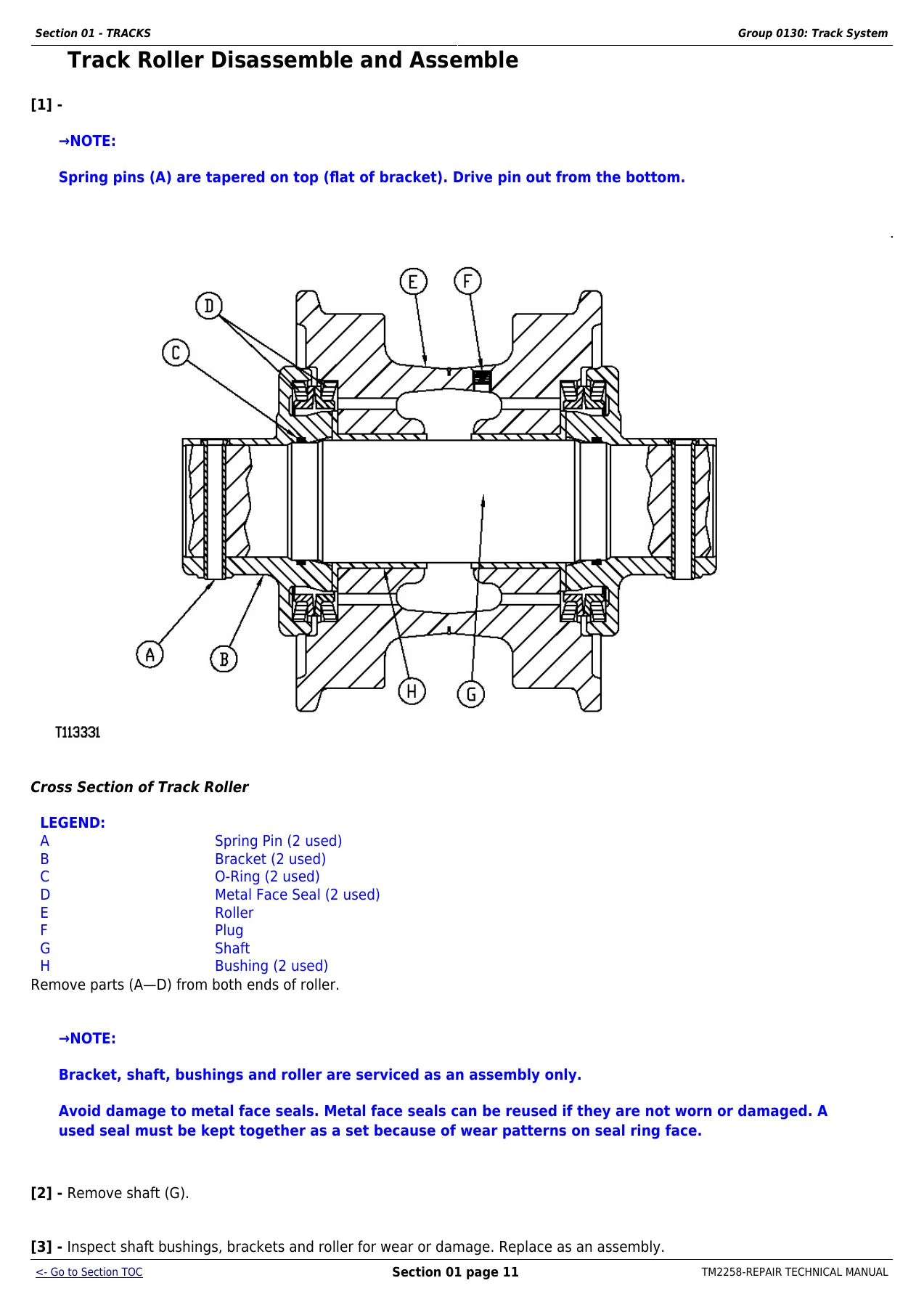
Track Roller Disassemble and Assemblep. 65
Track Roller Leakage Testp. 66
Track Shoe Remove and Installp. 68
Sealed Track Chain Removalp. 71
Sealed Track Chain Disassemble and Assemblep. 76
Sealed Track Chain Installationp. 77
Lubricated Track Chain (Saw Tooth Master Split Link) Remove and Installp. 79
Lubricated Track Chain Disassembly (Turn Bushings and Lubricate Chain)p. 83
Lubricated Track Chain Assembly (Turn Bushings and Lubricate Chain)p. 87
Lubricated Track Chain Disassemble and Assemble (Turn Pins and Not Lubricate)p. 96
Front Idler Remove and Installp. 103
Front Idler Disassemble, Inspect, and Assemblep. 104
Front Idler Adjustmentp. 107
Front Idler Oil Level Checkp. 108
Track Tension Adjuster Remove and Disassemblep. 110
Track Tension Adjuster Assemble and Installp. 111
Track Idler Recoil Spring Remove and Installp. 114
Track Idler Recoil Spring Disassemble and Assemblep. 116
Sprocket Remove and Installp. 121
Track Frame Remove and Installp. 123
Track Frame Disassemble and Assemblep. 124
Frame Wear Strips Remove and Installp. 127
Section 02 – AXLES AND SUSPENSION SYSTEMSp. 130
Group 0201 – Drive Axle Housing and Supportp. 130
Final Drive Remove and Installp. 130
Group 0250 – Axle Shaft, Bearings, and Reduction Gearp. 135
Final Drive Disassemble and Assemblep. 135
Section 03 – TRANSMISSIONp. 150
Group 0300 – Removal and Installationp. 150
Hydrostatic Pump Remove and Installp. 150
Hydrostatic Motor Remove and Installp. 162
Group 0315 – Controls Linkagep. 165
Transmission Control Lever (TCL) Remove and Installp. 165
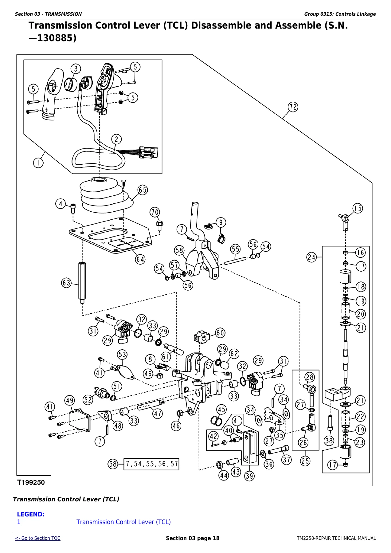
Transmission Control Lever (TCL) Disassemble and Assemble (S.N. β€”130885)p. 167
Group 0360 – Hydrostatic Systemp. 188
Hydrostatic Pumps Disassemblep. 188
Hydrostatic Charge Pump Disassemble and Assemblep. 201
Pump Displacement Control Valve (PDCV) Disassemble and Assemblep. 206
Multi-Function Valve Disassemble and Assemblep. 210
Neutral Charge Relief Valve Disassemble and Assemblep. 211
Hydrostatic Pump Assemblep. 213
Hydrostatic Motor Disassemblep. 225
Hydrostatic Motor Assemblep. 231
Oil Cooler Thermal Bypass Valve Remove and Installp. 248
Hydrostatic Filter Remove and Installp. 248
Hydrostatic Filter Disassemble and Assemblep. 250
Hydrostatic Reservoir Remove and Installp. 252
Section 04 – ENGINEp. 257
Group 0400 – Removal and Installationp. 257
Engine Remove and Installp. 257
Section 05 – ENGINE AUXILIARY SYSTEMSp. 267
Group 0505 – Cold Weather Starting Aidsp. 267
Engine Coolant Heater Remove and Installp. 267
Start Aid Remove and Installp. 268
Starting Aid Solenoid Remove and Installp. 269
Group 0510 – Radiator and Fan Shroudp. 271
Fan Blade and Shroud Remove and Install (450J, 550J)p. 271
Fan Blade and Shroud Remove and Install (650J)p. 273
Cooling Package Remove and Install (450J, 550J)p. 275
Cooling Package Remove and Install (650J)p. 277
Sand Shield Remove and Installp. 281
Group 0515 – Engine Speed Controlp. 282
Decelerator/Brake Pedal Remove and Installp. 282
Decelerator/Brake Pedal Disassemble and Assemblep. 283
Group 0520 – Intake Systemp. 289
Air Cleaner Remove and Install 550J and 650Jp. 289
Group 0530 – External Exhaust Systemp. 291
Muffler Without Turbocharger Remove and Installp. 291
Muffler With Turbocharger Remove and Installp. 292
Group 0540 – Mounting Framep. 293
Engine and Power Train Mountingp. 293
Group 0560 – External Fuel Supply Systemp. 295
Fuel Tank Remove and Installp. 295
Section 07 – DAMPENER DRIVEp. 298
Group 0752 – Elementsp. 298
Dampener Drive Remove and Installp. 298
Section 11 – PARK BRAKEp. 301
Group 1100 – Removal and Installationp. 301
Park Brake Valve Remove and Installp. 301
Park Brake Remove and Installp. 302
Group 1115 – Control Linkagep. 306
Park Lock Linkage Remove and Installp. 306
Park Lock Linkage Disassemble and Assemblep. 308
Group 1160 – Hydraulic Systemp. 311
Park Brake Valve Disassemble and Assemblep. 311
Park Brake Disassemble and Assemblep. 313
Section 18 – OPERATORβ€²S STATIONp. 318
Group 1800 – Removal and Installationp. 318
Cab or ROPS Remove and Installp. 318
Group 1810 – Operatorβ€²s Enclosurep. 327
Slide Glass Remove and Installp. 327
Stationary Glass Remove and Installp. 329
Sliding Window Remove and Installp. 331
Front Window Wiper Remove and Installp. 333
Door Window Wipers Remove and Installp. 335
Rear Window Wiper Remove and Installp. 337
Window Washer Pumps Remove and Installp. 338
Group 1821 – Seat and Seat Beltp. 339
Standard Seat Remove and Install (Old)p. 339
Deluxe Seat Remove and Installp. 344
Air Suspension Seat Remove and Installp. 354
Group 1830 – Heating and Air Conditioningp. 356
R134a Refrigerant Cautionsp. 356
R134a Compressor Oil Charge Checkp. 356
R134a Compressor Oil Removalp. 357
R134a Component Oil Chargep. 358
Leakage Testingp. 359
R134a Refrigerant Recovery, Recycling and Charging Station Installation Procedurep. 360
Recover R134a Systemp. 362
Evacuate R134a Systemp. 364
Charge R134a Systemp. 366
Air Conditioner System Cleaning Proceduresp. 367
Purge R134a Systemp. 367
Flush R134a Systemp. 369
Evaporator or Heater Core Remove and Installp. 372
Expansion Valve Remove and Installp. 374
A/C Freeze Switch Remove and Installp. 375
Upper Cab Heater Blower Motor and Heater Blower Resistor Remove and Installp. 375
Cab Upper Heater Disassemble and Assemblep. 377
Cab or ROPS Under Seat Heater Disassemble and Assemblep. 379
Receiver-Dryer Remove and Installp. 381
Condenser Remove and Installp. 382
Compressor Remove and Installp. 383
Compressor Remove and Installp. 386
Compressor Clutch Disassemble and Assemblep. 388
Clutch Hub Clearance Checkp. 390
Compressor Manifold Inspectp. 391
Compressor Disassemble and Assemblep. 392
Section 19 – SHEET METAL AND STYLINGp. 397
Group 1910 – Hood and Engine Enclosurep. 397
Hood Remove and Installp. 397
Hood Support and Engine Side Shields Remove and Installp. 399
Group 1921 – Grille and Grille Housingp. 400
Grille and Grille Housing Removalp. 400
Grille and Grille Housing Installationp. 402
Section 21 – MAIN HYDRAULIC SYSTEMp. 408
Group 2160 – Hydraulic Systemp. 408
Hydraulic Pump Remove and Installp. 408
Hydraulic Pump (With Winch Option) Disassemble and Assemblep. 412
Hydraulic Pump (Without Winch Option) Disassemble and Assemblep. 417
Hydraulic Reservoir Remove and Installp. 420
Hydraulic Reservoir and Hydrostatic Reservoir Cleanout Cover Remove and Installp. 424
Hydraulic Reservoir Disassemble and Assemblep. 428
Hydraulic Filter Remove and Installp. 429
Hydraulic Filter Disassemble and Assemblep. 430
Section 32 – BULLDOZERp. 432
Group 3201 – Bladesp. 432
Blade Remove and Installp. 432
Blade Ball and Socket Alignment Procedurep. 436
Blade Retainer Split Bearing Installationp. 438
Cutting Edges and End Bits Remove and Installp. 440
Group 3215 – Control Linkagep. 441
Hydraulic Control Lever Linkage Remove and Installp. 441
Auxiliary Hydraulic Control Lever Linkage Remove and Installp. 444
Group 3240 – Framesp. 446
C-Frame Remove and Installp. 446
Group 3260 – Hydraulic Systemp. 450
Hydraulic Control Valve Remove and Installp. 450
Hydraulic Control Valve Disassemble and Assemblep. 452
Wiper Seals and Lip Seals on Hydraulic Control Valve Remove and Installp. 454
Auxiliary Control Valve Section Disassemble and Assemblep. 460
Angle Control Valve Section Disassemble and Assemblep. 462
Tilt Control Valve Section Disassemble and Assemblep. 465
Lift Control Valve Section Disassemble and Assemblep. 467
Integrated Grade Control (IGC) Lever Remove and Install (S.N. 130886β€”)p. 470
Integrated Grade Control (IGC) Lever Disassemble and Assemble (S.N. 130886β€”)p. 473
System and Angle Circuit Relief Valve Disassemble and Assemblep. 475
Tilt Cylinder Remove and Installp. 475
Angle Cylinder Remove and Installp. 476
Lift Cylinder Remove and Installp. 478
Angle, Lift, and Tilt Cylinders Disassemble and Assemble (John Deere 120 Series Cylinders)p. 479
Section 9900 – DEALER FABRICATED TOOLSp. 481
Group 0999 – Dealer Fabricated Toolsp. 481
DF1041 Track Nut Removal Toolp. 481
DF1063 Final Drive Lift Bracketp. 482
DFT1087 Track Recoil Spring Disassembly and Assembly Guard Toolp. 484
DFT1119 Pump Supportp. 485
DFT1130 Adapterp. 486
DFT1132 Hydrostatic Motor Removal and Installation Toolp. 487
DFT1137 Hydrostatic Motor Removal and Installation Toolp. 488
DFT1165 Left Hand Hydrostatic Motor Lifting Bracketp. 489
DFT1166 Final Drive Lifting Bracket Adapterp. 490
DFT1167 Final Drive Lifting Bracket Adapter Spacerp. 491
DFT1168 Right Hand Hydrostatic Motor Lifting Bracketp. 492
DFT1211 Final Drive Lifting Bracket Adapterp. 493
DFRW20 Compressor Holding Fixturep. 494
ST4920 Track Recoil Spring Disassembly and Assembly Toolp. 495

Across 498 pages the TM2258 repair manual gives a technician the full disassembly-to-reassembly path for the 450J, 550J and 650J, from the track system and final drives through the hydrostatic tandem pump and motor, the park brake assembly, the operator station and the complete bulldozer blade hydraulics. Sub-assemblies are broken down with torque values, wear limits and preload/end play figures published alongside each procedure, and the Dealer Fabricated Tools section documents the lifting brackets, seal drivers and press adapters needed to handle the heavy components safely.

What This Manual Helps You Do

The 450J, 550J and 650J Repair Technical Manual is what you reach for when a crawler dozer needs more than a filter change: rebuilding the track chains and turning the pins and bushings, resealing a leaking final drive, pulling the hydrostatic tandem pumps to service the charge pump or swash plate, resetting the pump displacement control valve to its neutral (null) position, chasing down an oil cooler thermal bypass fault, or setting up the blade ball and socket with the correct shim stack. Because the manual was written around the machine’s specific serial number range, the torque tables, shim counts and preload figures match the dozer in front of you instead of a generic average of several generations.

For the shop, the practical value comes from the depth of the hydraulic and transmission coverage. The hydrostatic system section alone walks through the tandem pump, charge pump, pump displacement control valve, multi-function valve, neutral charge relief valve, hydrostatic motor and the oil cooler bypass circuit, and it explains how to disassemble, clean, inspect, reassemble and re-time each of those components. The track section goes well past part-swapping, covering metal face seal inspection, bushing projection measurement, pin chamfer restoration, the track roller leakage test and the correct pressing sequence to avoid broaching a link. The bulldozer section then ties that drivetrain work back to the blade itself with control valve spool and seal service, work port relief and system relief valve procedures, and C-frame removal.

Delivery

IMAGES PREVIEW

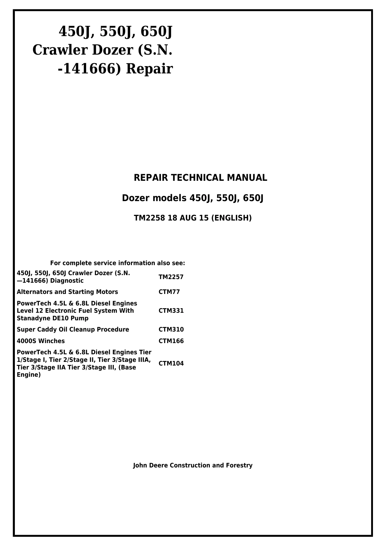
John Deere 450J 550J 650J Crawler Dozer Repair Technical Manual TM2258 PDF β€” PDF page 1 preview
John Deere 450J 550J 650J Crawler Dozer Repair Technical Manual TM2258 PDF β€” PDF page 65 preview
John Deere 450J 550J 650J Crawler Dozer Repair Technical Manual TM2258 PDF β€” PDF page 167 preview

This is a digital PDF download of the John Deere 450J 550J 650J Crawler Dozer Repair Technical Manual TM2258. There is no physical book to ship and nothing to wait for beyond the checkout β€” the file is delivered instantly after payment, opens on any phone, tablet, laptop or desktop PDF reader, and can be printed page-by-page for use in the shop or kept on a device at the machine. Every section, table and illustration is included exactly as published so the torque values, clearances and procedures stay together in the order they were written.
Reviews

There are no reviews yet.

Be the first to review “John Deere 450J 550J 650J Crawler Dozer Repair Technical Manual TM2258 PDF”

What Our Customers Say

β˜…β˜…β˜…β˜…β˜… Live reviews from customers
Loading customer reviews...
0
    0
    Your Cart
    Your cart is emptyReturn to Shop
    πŸ›’
    Recently Purchased
    πŸ•’ verified order