★ TRUSTED BY 321,897+ PROFESSIONALS WORLDWIDE
🏢
Trusted Business
Verified & Licensed
🛡️
Virus Free Files
100% Safe Downloads
🔒
Secure Payment
SSL Protected
Instant Delivery
Available Immediately
Sale!

John Deere 5105 5205 Tractor Technical Manual TM1792 (2000) Repair & Tests PDF

Original price was: $39.95.Current price is: $24.95.

Complete John Deere 5105 and 5205 Tractors Technical Manual TM1792 – repair, operation, tests and adjustments for every major system on both models. Instant PDF download.

Instant PDF Download
Available immediately
💾
Save to Your Device
Download & keep forever
🛡️
Antivirus Scanned
100% virus-free
🌍
Trusted Worldwide
175,000+ customers

Description

John Deere 5105 and 5205 Tractors Technical Manual TM1792

This John Deere 5105 and 5205 Tractors Technical Manual (TM1792, dated 20 March 2000) is the complete workshop reference for the 5105 and 5205 utility tractors. Published by Deere & Company, it covers general information, engine repair, fuel and air systems, electrical repair, power train repair, steering and brake repair, hydraulic repair, miscellaneous repair, operator station repair, and the full operation, tests and adjustments sections for every major system on the machine.

Written for the experienced technician, the manual is organised into repair groups and diagnostic groups so that both component overhaul and fault-finding are supported. The repair sections show how to remove, disassemble, inspect, assemble and install components. The operation, tests and adjustments sections help identify routine failures quickly with component locations, theory of operation and step-by-step diagnostics.

File Details

  • Manual type: Technical Manual (Repair and Operation/Tests)
  • Brand: John Deere
  • Models covered: 5105 and 5205 Tractors
  • Document number: TM1792
  • Edition/date: 20 March 2000 (20MAR00)
  • Publisher: Deere & Company, Moline, Illinois
  • Language: English
  • File format: PDF

Complete PDF Bookmark Tree

Complete Bookmarks

The complete bookmarks in the “John Deere 5105 5205 Tractor Technical Manual TM1792 (2000) Repair & Tests PDF” are as follows:

TM1792 – 5105 and 5205 Utility Tractorsp. 1
Introductionp. 2
Contentsp. 3
General Informationp. 7
Safetyp. 9
Recognize Safety Informationp. 9
Understand Signal Wordsp. 9
Follow Safety Instructionsp. 9
Handle Fluids Safely—Avoid Firesp. 10
Prevent Battery Explosionsp. 10
Prepare for Emergenciesp. 10
Prevent Acid Burnsp. 11
Service Cooling System Safelyp. 11
Handle Chemical Products Safelyp. 12
Avoid High-Pressure Fluidsp. 12
Park Machine Safelyp. 13
Support Machine Properlyp. 13
Wear Protective Clothingp. 13
Work in Clean Areap. 14
Service Machines Safelyp. 14
Work in Ventilated Areap. 14
Illuminate Work Area Safelyp. 14
Replace Safety Signsp. 15
Use Proper Lifting Equipmentp. 15
Keep ROPS Installed Properlyp. 15
Service Tires Safelyp. 16
Avoid Harmful Asbestos Dustp. 16
Avoid Heating Near Pressurized Fluid Linesp. 17
Remove Paint Before Welding or Heatingp. 17
Use Proper Toolsp. 18
Dispose of Waste Properlyp. 18
Live With Safetyp. 19
General Specificationsp. 21
Machine Specificationsp. 21
Drain and Refill Capacitiesp. 23
Machine Dimensionsp. 24
Ground Speed Estimatesp. 29
Service Recommendations for O-Ring Boss Fittingsp. 35
Service Recommendations for Flat Face O-Ring Seal Fittingsp. 37
Metric Bolt and Cap Screw Torque Valuesp. 38
Unified Inch Bolt and Cap Screw Torque Valuesp. 39
Fuel and Lubricantsp. 41
Diesel Fuelp. 41
Fuel Storagep. 42
Do Not Use Galvanized Containersp. 42
Fill Fuel Tankp. 43
Diesel Engine Oilp. 44
Engine Coolantp. 45
Liquid Coolant Conditionerp. 45
Transmission and Hydraulic Oilp. 46
MFWD Gear Oilp. 47
Grease (Specific Application)p. 47
Greasep. 48
Alternative and Synthetic Lubricantsp. 48
Lubricant Storagep. 49
Serial Number Locationsp. 51
Serial Numbersp. 51
Product Identification Number Locationp. 51
Engine Serial Number Locationp. 51
Fuel Injection Pump Serial Number Locationp. 51
Alternator Serial Number Locationp. 52
Power Steering Valve Serial Number Locationp. 52
Starter Serial Number Locationp. 52
Transmission Serial Number Locationp. 52
Front Axle (2WD) Serial Number Locationp. 53
Mechanical Front Wheel Drive (MFWD) Serial Number Locationp. 53
Features and Accessoriesp. 55
Standard Featuresp. 56
Factory Installed Optional Equipmentp. 58
Field Installed Optional Kits and Accessoriesp. 59
Engine Repairp. 61
Enginep. 63
Service Equipment and Toolsp. 63
Specificationsp. 63
John Deere Engine Repair—Use CTM8p. 63
Remove Enginep. 64
Install Enginep. 69
Cooling Systemp. 75
Specificationsp. 75
Engine Water Pump Repair—Use CTM8p. 75
Remove, Inspect and Install Radiatorp. 75
Replace Thermostatp. 78
Fuel and Air Repairp. 79
Fuel Systemp. 81
Specificationsp. 81
Injection Pump, Nozzle and Governor Repair—Use CTM8p. 81
Remove, Inspect and Install Fuel Tankp. 81
Replace Fuel Filterp. 83
Remove and Install Fuel Filter/Primer Pump Assemblyp. 83
Air Intake Systemp. 85
Remove, Inspect, and Install Air Cleaner Elementsp. 85
Speed Control Linkagep. 87
Inspect and Repair Speed Control Linkagep. 87
Electrical Repairp. 89
Battery, Starter and Alternatorp. 91
Starter Repair—Use CTM77p. 91
Remove and Install Batteryp. 91
Remove and Install Starterp. 92
Replace Alternator/Regulatorp. 93
Electrical System Componentsp. 95
Service Equipment and Toolsp. 95
Other Materialp. 95
Replace Air Filter Restriction Sensorp. 96
Replace Coolant Temperature Senderp. 96
Replace Engine Speed Sensorp. 97
Replace Engine Oil Pressure Sensorp. 97
Replace Key Switchp. 98
Replace Light Switchp. 99
Replace Turn Signal Controllerp. 100
Replace Instrument Panelp. 100
Replace Rear PTO Switchp. 102
Replace Neutral Start Switchp. 102
Replace Seat Switchp. 103
Replace Fuel Level Senderp. 104
Wiring Harnessp. 105
Special or Essential Toolsp. 105
Service Parts Kitsp. 105
Remove Connector Body from Blade Terminalsp. 105
Replace WEATHER PACK™ Connectorp. 106
Install WEATHER PACK™ Contactp. 107
Replace Tractor Wiring Harnessp. 108
Power Train Repairp. 111
Clutch Housingp. 113
Specificationsp. 113
Separate Engine from Transmission Housingp. 113
Install Engine to Transmission Housingp. 116
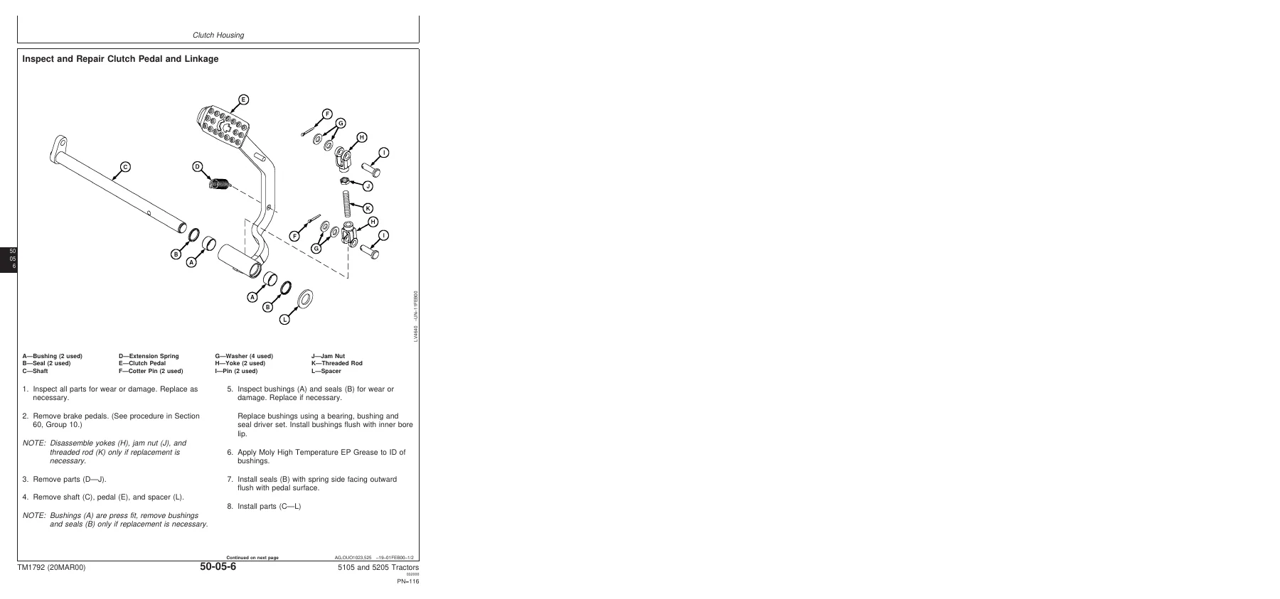
Inspect and Repair Clutch Pedal and Linkagep. 118
Clutch Assemblyp. 121
Other Materialp. 121
Essential Toolsp. 121
Specificationsp. 122
Remove and Install Clutch Assemblyp. 122
Disassemble and Inspect Clutch Assemblyp. 125
Assemble Clutch Assemblyp. 132
Traction Clutch Finger Adjustmentp. 138
PTO Clutch Finger Adjustmentp. 139
Remove and Inspect Clutch Release Mechanism and Shaftsp. 140
Install Clutch Release Mechanism and Shaftsp. 143
Transmissionp. 147
Other Materialp. 147
Specificationsp. 147
Remove, Inspect and Repair Gear Shift Lever And Coverp. 148
Remove, Inspect and Install Range and Reverse Shift Leverp. 149
Remove Transmissionp. 150
Disassemble and Inspect Transmissionp. 151
Assemble Transmissionp. 156
Install Transmissionp. 161
Disassemble, Inspect and Assemble Shift Shaft Assembliesp. 163
Disassemble, Inspect, and Assemble Transmission Top Driven Shaftp. 164
Disassemble, Inspect and Assemble Range Reduction Shaftp. 166
Disassemble, Inspect and Assemble Driven Shaftp. 168
Disassemble, Inspect and Assemble Traction Clutch Driven Shaftp. 170
Disassemble, Inspect and Assemble Synchronizerp. 172
Rear PTOp. 175
Other Materialp. 175
Specificationsp. 175
Remove, Inspect and Install Rear PTO Lever and Linkagep. 176
Remove and Install Rear PTO Drive Shaft Assemblyp. 178
Disassemble, Inspect and Assemble Rear PTO Drive Shaft Assemblyp. 179
Differentialp. 181
Essential Toolsp. 181
Other Materialp. 181
Specificationsp. 182
Remove and Install Differential Assemblyp. 183
Disassemble, Inspect and Assemble Differential Assemblyp. 184
Remove and Inspect Differential Drive Shaftp. 185
Install Differential Drive Shaftp. 188
Remove, Inspect and Install Differential Lock Assemblyp. 192
Differential Cone Point Adjustmentp. 193
Differential Backlash Adjustmentp. 194
Final Drivesp. 195
Essential Toolsp. 195
Service Equipment and Toolsp. 195
Other Materialp. 196
Specificationsp. 196
Remove and Install Final Drive Assemblyp. 197
Remove and Inspect Planetary Drive Assemblyp. 198
Install Planetary Drive Assemblyp. 199
Remove, Inspect, and Install Axle Shaft Assemblyp. 201
Mechanical Front Wheel Drivep. 205
Essential Toolsp. 205
Other Materialp. 206
Specificationsp. 207
Inspect and Repair MFWD Lever and Linkagep. 208
Remove and Install MFWD Drop Gearboxp. 209
Disassemble and Inspect MFWD Drop Gearboxp. 211
Remove, Inspect and Install MFWD Drive Shaftp. 217
Remove and Install MFWD Axle Housing Assemblyp. 218
Remove, Inspect and Install MFWD Axle Supportsp. 220
Disassemble and Inspect MFWD Outer Drivep. 221
Assemble MFWD Outer Drivep. 224
Remove, Inspect and Install MFWD Swivel Housingp. 226
Remove, Inspect and Install MFWD Axle Shaftp. 229
Remove and Install MFWD Differential Carrier Assemblyp. 231
Disassemble and Inspect MFWD Differential Carrier Assemblyp. 232
Assemble MFWD Differential Carrier Assemblyp. 236
Steering and Brake Repairp. 245
Steering Repairp. 247
Other Materialp. 247
Specificationsp. 247
Service Parts Kitsp. 248
Remove and Install Steering Column and Valvep. 249
Disassemble and Inspect Steering Valvep. 250
Assemble Steering Valvep. 253
Remove and Install Steering Cylinder—2WD Axlep. 257
Disassemble, Inspect and Assemble Steering Cylinder—2WD Axlep. 258
Remove and Install Steering Cylinder—MFWD Axlep. 259
Disassemble, Inspect and Assemble Steering Cylinder—MFWD Axlep. 261
Remove, Inspect and Install Tie Rod Assembly—2WD Axlep. 262
Remove, Inspect and Install Tie Rod Assembly—MFWD Axlep. 263
Inspect and Replace Steering Hydraulic Lines—Tractor With 2WDp. 264
Inspect and Replace Steering Hydraulic Lines—Tractor With MFWDp. 266
Brake Repairp. 269
Other Materialp. 269
Specificationsp. 269
Remove and Install Brake Pedals and Linkagep. 270
Remove and Install Park Brake Lever and Linkagep. 272
Remove and Inspect Brakesp. 273
Install Brakesp. 274
Hydraulic Repairp. 277
Hydraulic Pump and Filterp. 279
Specificationsp. 279
Service Parts Kitsp. 279
Remove, Inspect, and Install Hydraulic Oil Pick-Up Screenp. 280
Remove and Install Hydraulic Pumpp. 281
Remove Hydraulic Pump External Componentsp. 282
Disassemble and Inspect Hydraulic Pumpp. 283
Assemble Hydraulic Pumpp. 285
Install Hydraulic Pump External Componentsp. 287
Remove and Install Hydraulic Oil Filter/Manifoldp. 288
Inspect and Replace Hydraulic Supply and Suction/Return Linesp. 289
Rockshaftp. 291
Other Materialp. 291
Specificationsp. 292
Remove, Inspect, and Install Rockshaft Control Lever Assemblyp. 293
Remove, Inspect, and Install Rockshaft Control Lever Support Assemblyp. 295
Remove, Inspect and Install Rockshaft Control Linkagep. 302
Remove, Inspect, and Install Draft Sensing Support Assemblyp. 309
Remove and Install Inlet Valvep. 313
Replace Main Relief Valvep. 314
Remove, Inspect and Install Rate-of-Drop Valvep. 314
Replace Rockshaft Control Valvep. 316
Remove and Install Rockshaft Casep. 319
Remove, Inspect and Install Rockshaft Lift Armsp. 320
Remove, Inspect and Install Rockshaft Piston and Cylinderp. 324
Selective Control Valve (SCV)p. 327
Other Materialp. 327
Specificationsp. 327
Remove and Install Regenerative Selective Control Valve (SCV)p. 328
Disassemble, Inspect and Assemble Regenerative Selective Control Valve (SCV)p. 330
Inspect and Replace Hydraulic Lines—Regenerative Selective Control Valve (SCV)p. 332
Remove and Install Float Selective Control Valve (SCV)p. 334
Disassemble, Inspect and Assemble Float Selective Control Valve (SCV)p. 336
Inspect and Replace Hydraulic Lines—Float Selective Control Valve (SCV)p. 337
Hydraulic Mid Mount Couplerp. 339
Other Materialp. 339
Specificationsp. 339
Remove and Install Mid Mount Control Valvep. 340
Disassemble, Inspect and Assemble Mid Mount Control Valvep. 342
Inspect and Replace Hydraulic Hoses—Mid Mount Couplerp. 344
Remove, Inspect and Install Joystick and Linkage—Mid Mount Couplerp. 345
Disassemble, Inspect, and Assemble Joystick—Mid Mount Couplerp. 347
Miscellaneous Repairp. 349
Front Axle—2WDp. 351
Specificationsp. 351
Remove and Install Front Axle—2WDp. 351
Inspect and Replace Pivot Pin and Bushings—2WD Axlep. 353
Remove and Install Spindle Assembly—2WD Axlep. 354
Inspect and Replace Spindle Shaft Bushings—2WD Axlep. 355
Wheelsp. 357
Specificationsp. 357
Inspect and Replace Front Wheel Bearingsp. 357
3-Point Hitchp. 359
Specificationsp. 359
Inspect and Repair Fixed Draft Linksp. 359
Inspect and Repair Telescoping Draft Linksp. 361
Inspect and Repair Standard Lift Linkp. 363
Inspect and Repair Adjustable Lift Linkp. 364
Inspect and Repair Center Linkp. 365
Remove and Install Drawbar and Supportp. 366
Operator Station Repairp. 367
Seat and Supportp. 369
Specificationsp. 369
Remove and Install Seat and Supportp. 369
ROLL-GARD™p. 371
Specificationsp. 371
Remove and Install ROLL-GARD™p. 371
Operator Platformp. 375
Specificationsp. 375
Remove and Install Right-Side Platformp. 375
Remove and Install Left-Side Platform and Stepp. 380
Fendersp. 385
Remove and Install Fendersp. 385
Operational Checkout Proceduresp. 387
Operational Checkout Proceduresp. 389
Operational Checkout Procedure Informationp. 389
Engine Oil Level and Condition Checkp. 390
Coolant Level and Condition Checkp. 391
Transmission and Hydraulic Oil Checkp. 392
Fan and Belt Checkp. 393
Fuel System Checkp. 394
Air Intake System Checkp. 395
Electrical System Checkp. 396
Hydraulic System Checkp. 397
MFWD Oil Checkp. 398
Indicator Lamps Checkp. 399
Engine Start Checkp. 400
Transmission Neutral Start Checkp. 401
PTO Neutral Start Checkp. 402
Engine Fast and Slow Idle Operationp. 403
Power Steering Checkp. 404
Differential Lock Checkp. 405
PTO Engagement Checkp. 406
Clutch Checkp. 407
Transmission Shift Checkp. 408
Range Lever Shift Checkp. 409
MFWD Drive Checkp. 410
Brake Checkp. 411
Rockshaft Checkp. 412
Selective Control Valve Checkp. 413
Mid-Mount Coupler Control Valve Check—(Optional Equipment)p. 414
Miscellaneous Checksp. 415
Engine Operation, Tests and Adjustmentsp. 417
Component Locationp. 419
Component Location Informationp. 419
Engine External Components—Left-Hand Sidep. 420
Engine External Components—Right-Hand Sidep. 421
Theory of Operationp. 423
Theory of Operation Informationp. 423
Engine Lubrication System Operationp. 424
Engine Cooling System Operationp. 428
Diagnosis, Tests and Adjustmentsp. 431
Specificationsp. 431
Essential Toolsp. 432
Diagnostic Informationp. 433
Engine Turns Over But Will Not Start or Starts Hardp. 434
Engine Runs Irregularly or Stalls Frequentlyp. 435
Engine Runs Roughp. 436
Engine Low Powerp. 437
Engine Smokes—Black or Greyp. 438
Engine Smokes Excessively—Whitep. 439
Engine Uses Excess Fuelp. 440
Engine Has Excess Noise or Vibrationp. 441
Engine Uses Excess Oil or Smokes Bluep. 442
Engine Has Low Oil Pressurep. 442
Engine Coolant Operating Temperature Incorrectp. 443
Oil In Coolant or Coolant in Oilp. 444
Radiator Bubble Testp. 445
Cooling System Testp. 447
Radiator Cap Pressure Testp. 448
Engine Oil Pressure Testp. 449
Cylinder Compression Pressure Testp. 451
Fuel Shut-Off Solenoid Checkp. 452
Throttle Lever Adjustmentp. 453
Slow Idle Adjustmentp. 454
Fast Idle Adjustmentp. 455
Injection Pump Timing Adjustmentp. 456
Valve Clearance Adjustmentp. 457
Fan/Alternator Drive Belt Adjustmentp. 459
Bleed Fuel Systemp. 461
Fuel/Air Operation, Tests and Adjustmentsp. 463
Component Locationp. 465
Component Location Informationp. 465
Fuel System Componentsp. 466
Air Intake System Componentsp. 468
Theory of Operationp. 471
Theory of Operation Informationp. 471
Fuel System Operationp. 472
Fuel Filter/Priming Pump Operationp. 474
Fuel Injection Nozzle Operationp. 476
Air Intake System Operationp. 478
Diagnosis, Tests and Adjustmentsp. 481
Diagnostic Informationp. 481
Fuel/Air Diagnosis, Tests and Adjustmentsp. 481
Electrical System Operation, Tests & Adjustp. 483
Component Locationp. 485
Component Location Informationp. 485
Engine Electrical Components—Right Hand Sidep. 486
Engine Electrical Components—Left Hand Sidep. 487
Dash And Center Control Console Electrical Componentsp. 488
Tractor Electrical Components—5105-5205p. 490
Theory of Operationp. 493
Theory of Operation Informationp. 493
Fuse Block and Fusesp. 494
Relaysp. 496
Starting System Operation—Normalp. 498
Starting System Operation—Bypass Attemptp. 500
Manifold Heater System Operationp. 502
Charging System Operationp. 504
Lighting System Operation—Turn Signals And Enhanced Tail Lightsp. 506
Lighting System Operation—Warning Lightsp. 508
Lighting System Operation—Tail Lightsp. 510
Lighting System Operation—Headlights and Instrument Lightsp. 512
Instrument Panel System Operation—Tachometer/Hour Meterp. 514
Instrument Panel System Operation—Fuel Gaugep. 516
Instrument Panel System Operation—Temperature Gaugep. 518
PTO Warning System Operationp. 520
Air Filter Restriction Indicator Operationp. 522
7-Pin Trailer Outlet Connector Operationp. 524
Optional Horn Operationp. 526
Optional Rear Work Lightp. 527
Diagnosis, Test and Adjustp. 529
Diagnostic Informationp. 529
Wire Color Chartp. 530
Starting System Test Points—Normal Operationp. 531
Starting System Test Points—Bypass Attemptp. 539
Manifold Heater Test Pointsp. 545
Charging System Test Pointsp. 549
Lighting System Test Points—Turn Signals And Enhanced Tail Lightsp. 555
Lighting System Test Points—Warning Lightsp. 571
Lighting System Test Points—Rear Flood Light (Optional Equipment)p. 575
Lighting System Test Points—Headlights and Instrument Lightsp. 579
Instrument Panel System Test Points—Tachometer/Hourmeterp. 589
Instrument Panel System Test Points—Fuel Gaugep. 595
Instrument Panel System Test Points—Temperature Gaugep. 599
Instrument Panel System Test Points—Oil Pressurep. 605
PTO Warning System Test Pointsp. 611
Air Filter Restriction Test Pointsp. 617
Optional Horn Test Pointsp. 623
Accessory Relay and Trailer Connector Test Pointsp. 627
Battery Voltage and Specific Gravity Testsp. 633
Charge Batteryp. 635
Battery Load Testp. 637
Starter AMP Draw/RPM Testp. 639
Starter No-Load AMP Draw/RPM Testp. 641
Alternator/Regulator Testp. 642
Starter Solenoid Testp. 643
Starter Relay Testp. 644
Key Switch Testp. 645
Plug-In Relay Testp. 646
Mini Plug-In Relayp. 647
Diode Pack Testp. 648
Fuse Testp. 649
Neutral Start Switch Testp. 650
PTO Switch Testp. 651
PTO Seat Switch Testp. 652
Light Switch Testp. 653
Turn Signal Controller Testp. 654
Fuel Shut-Off Solenoid Testp. 655
Wiring Schematicsp. 657
Schematic Informationp. 657
Component Identification Tablep. 657
5105 and 5205 Electrical Schematic Legendp. 659
5105 and 5205 Electrical Schematic Legendp. 665
Power Train Operation, Tests & Adjustmentsp. 671
Component Location—Power Trainp. 673
Component Location Informationp. 673
Power Train Componentsp. 674
Clutch Componentsp. 676
Transmission Componentsp. 678
Final Drive Componentsp. 680
Rear PTO Componentsp. 682
Theory of Operation—Transmissionp. 685
Theory of Operation Informationp. 685
Clutch Operationp. 686
Transmission Lubrication Systemp. 692
Transmission Power Flow—Gear Shiftp. 694
Transmission Power Flow—Range Shift and Reversep. 696
Transmission Operation—Reverse and A Range Synchronizerp. 698
Rear PTO Operationp. 700
Differential Power Flowp. 702
Differential Lock Operationp. 704
Final Drive Operationp. 706
Mechanical Front Wheel Drive (MFWD) Operationp. 708
Diagnosis, Tests and Adjustments—Power Trainp. 711
Diagnostic Informationp. 711
Isolate the Problem Areap. 712
Traction Clutch Slipsp. 713
Traction Clutch Draggingp. 714
Traction Clutch Does Not Engagep. 714
Traction Clutch Grabsp. 715
Traction Clutch Squeaksp. 715
Traction Clutch Does Not Releasep. 716
Traction Clutch Chattersp. 716
Traction Clutch Rattlesp. 717
Traction Clutch Engagement Is Noisyp. 717
Excessive Vibration in Traction Clutchp. 718
Clutch Pedal Does Not Returnp. 718
Clutch Pedal Loosep. 719
Clutch Pedal Pulsatesp. 719
Jerky or Rough Transmission of Powerp. 719
Low Transmission Oil Level (Excessive Oil Leakage)p. 720
Gears Clash, Shifts Hard, or Will Not Engagep. 720
Two Speeds Engage Togetherp. 721
Transmission Will Not Stay in Gearp. 721
Transmission Noisyp. 722
PTO Noisyp. 722
PTO Hard to Engagep. 723
PTO Will Not Operatep. 723
PTO Will Not Stay Engagedp. 723
PTO Clutch Slipsp. 724
PTO Clutch Draggingp. 724
PTO Clutch Does Not Engagep. 725
Excessive Differential Noisep. 725
Differential Does Not Workp. 726
Differential Chattersp. 726
Axle Noisep. 727
Axle Shaft Will Not Turnp. 727
MFWD Lever is Hard to Engagep. 728
MFWD Lever Will Not Stay in "ON" Positionp. 728
Noisy Front Wheel Drive Operationp. 729
Clutch Pedal Free Play Adjustmentp. 729
PTO Clutch Lever Adjustmentp. 730
Steering and Brake Operation, Test & Adjustp. 731
Component Locationp. 733
Component Location Informationp. 733
Steering System Componentsp. 734
Brake System Componentsp. 736
Theory of Operationp. 739
Theory of Operation Informationp. 739
Steering System Operationp. 740
Steering Valve Operation—Neutral and Manual Turningp. 742
Steering Valve Operation—Power Turningp. 744
Brake System Operationp. 746
Diagnosis, Tests and Adjustmentsp. 749
Specificationsp. 749
Diagnostic Informationp. 750
Isolate the Problem—Steering Systemp. 751
Steering Sluggish or Loss of Steeringp. 752
Isolate the Problem—Brakesp. 752
Steering Pump Flow Testp. 753
Steering Valve Relief Testp. 754
Steering Cylinder Leakage Testp. 755
Steering Valve Leakage Testp. 755
Toe-In Check and Adjustment—Standard Axlep. 757
Toe-In Check and Adjustment—MFWDp. 759
MFWD Steering Stop Adjustmentp. 761
Brake Pedal Adjustmentp. 762
Hydraulic System Operation, Test & Adjustp. 765
Component Locationp. 767
Component Location Informationp. 767
Hydraulic System Componentsp. 768
Selective Control Valve Componentsp. 770
Power Beyond Control Valve Componentsp. 772
Mid Mount Control Valve Componentsp. 774
Theory of Operationp. 777
Theory of Operation Informationp. 777
Hydraulic System Operationp. 778
Hydraulic Filter Operationp. 781
Hydraulic Pump Operationp. 783
Rockshaft Control Valve Operation—Neutral Positionp. 786
Rockshaft Control Valve Operation—Raise Positionp. 790
Rockshaft Control Valve Operation—Lower Positionp. 794
Surge Relief Valve Operationp. 798
Rate-of-Drop Valve Operation—Full Openp. 800
Rate-of-Drop Valve Operation—Partially Openp. 802
Rate-of-Drop Valve Operation—Full Closedp. 804
Rockshaft Draft-Sensing Operationp. 806
Float Selective Control Valve Operation—Neutral Positionp. 808
Regenerative Selective Control Valve Operation—Neutral Positionp. 810
Float Selective Control Valve Operation—Extend Positionp. 812
Regenerative Selective Control Valve Operation—Extend Positionp. 814
Float Selective Control Valve Operation—Retract Positionp. 816
Regenerative Selective Control Valve Operation—Retract Positionp. 818
Float Selective Control Valve Operation— Float Positionp. 820
Regenerative Selective Control Valve Operation—Regenerative Positionp. 822
Quick Disconnect Coupler Operationp. 824
Diagnosisp. 827
Diagnostic Informationp. 827
Preliminary Hydraulic System Inspectionp. 828
Hydraulic Oil Warm-Up Procedurep. 829
Entire Hydraulic System Fails to Function/No Hydraulic Pump Outputp. 830
Insufficient Pump Deliveryp. 830
Hydraulic Functions Too Slowp. 831
Excessive Pump Pressurep. 831
Slow Hydraulic Pump Responsep. 832
Excessive Pump Noise During Operationp. 832
Rockshaft Does Not Lift or Lifts Slowlyp. 833
Rockshaft Does Not Lower or Lowers Slowlyp. 833
Neutral Position Unstable, Rockshaft Drops after Engine Shut Downp. 834
SCV Control Lever Does Not Return to Neutral Position—Float SCVp. 835
SCV Lever Does Not Remain in Detent Position—Float SCVp. 835
SCV Lever Does Not Return to Neutral Position—Regenerative SCVp. 836
Remote Cylinder Does Not Extend or Retractp. 836
Remote Cylinder Settles Under Loadp. 837
Remote Cylinder Operates Too Fast or Too Slowp. 837
Mid Mount Control Valve Joystick Lever Does Not Return to Neutral Positionp. 838
Hydraulic Tests—Without SCVp. 839
Hydraulic System Tests—Without SCVp. 839
Pump Flow Test—Without SCVp. 840
Main Relief Valve Test—Without SCVp. 841
Hydraulic Tests—With SCVp. 843
Hydraulic System Tests—With SCVp. 843
Pump Flow Test—With SCVp. 844
Main Relief Valve Test—With SCVp. 845
SCV Leakage Testp. 846
Hydraulic Tests—With Mid Mount Control Valvep. 847
Hydraulic System Tests—With Mid Mount Control Valvep. 847
Pump Flow Test—With Mid Mount Control Valvep. 848
Main Relief Valve Test—With Mid Mount Control Valvep. 850
Mid Mount Control Valve Leakage Testp. 851
Hydraulic Tests—Allp. 853
Rockshaft Leakage Testp. 853
Rockshaft Lift Cycle Testp. 854
Adjustmentsp. 857
Rockshaft Sensing Lever Friction Adjustmentp. 857
Rockshaft Position-Sensing Lever Adjustmentp. 858
Rockshaft Draft-Sensing Lever Adjustmentp. 860
Mid Mount Control Valve Joystick Cable Adjustmentp. 861
Hydraulic Schematicsp. 863
Hydraulic Circuit Symbolsp. 863
Hydraulic Schematic—With Selective Control Valvep. 866
Hydraulic Schematic—With Mid Mount Control Valvep. 870
Hydraulic Schematic—With Selective Control Valve and Power Beyond Valvep. 874
Dealer Fabricated Toolsp. 879
Dealer Fabricated Toolsp. 881
DFLV1A Final Drive Turning Toolp. 881
Indexp. 883
Ap. 883
Bp. 883
Cp. 883
Dp. 883
Ep. 884
Fp. 885
Gp. 885
Hp. 885
Ip. 886
Jp. 886
Kp. 886
Lp. 886
Mp. 887
Np. 887
Op. 887
Pp. 888
Qp. 888
Rp. 888
Sp. 889
Tp. 890
Vp. 891
Wp. 891

Chapters Covered

  • Section 10 – General Information: Safety, general specifications, fuel and lubricants, serial number locations, features and accessories
  • Section 20 – Engine Repair: Engine, cooling system
  • Section 30 – Fuel and Air Repair: Fuel system, air intake system, speed control linkage
  • Section 40 – Electrical Repair: Battery, starter and alternator; electrical system components; wiring harness
  • Section 50 – Power Train Repair: Clutch housing, clutch assembly, transmission, rear PTO, differential, final drives, mechanical front wheel drive
  • Section 60 – Steering and Brake Repair: Steering repair, brake repair
  • Section 70 – Hydraulic Repair: Hydraulic pump and filter, rockshaft, selective control valve (SCV), hydraulic mid mount coupler
  • Section 80 – Miscellaneous Repair: Front axle 2WD, wheels, 3-point hitch
  • Section 90 – Operator Station Repair: Seat and support, ROLL-GARD, operator platform, fenders
  • Section 210 – Operational Checkout Procedures: Full machine operational checks
  • Section 220 – Engine Operation, Tests and Adjustments: Component location, theory of operation, diagnosis, tests and adjustments
  • Section 230 – Fuel/Air Operation, Tests and Adjustments: Component location, theory of operation, diagnosis, tests and adjustments
  • Section 240 – Electrical System Operation, Tests & Adjust: Component location, theory of operation, diagnosis, tests and adjustments, wiring schematics
  • Section 250 – Power Train Operation, Tests & Adjustments: Component location, theory of operation, diagnosis, tests and adjustments
  • Section 260 – Steering and Brake Operation, Tests & Adjust: Component location, theory of operation, diagnosis, tests and adjustments
  • Section 270 – Hydraulic System Operation, Tests & Adjust: Component location, theory of operation, diagnosis, hydraulic tests with and without SCV, hydraulic tests with mid mount control valve, hydraulic tests all, adjustments, hydraulic schematics
  • Section 299 – Dealer Fabricated Tools: DFLV1A final drive turning tool

Across these sections the manual gives you the engine specification tables for the 3029D POWERTECH 3-cylinder diesel, the drain and refill capacities, machine dimensions, ground speed estimates, torque values for metric and unified fasteners, O-ring boss and flat face O-ring seal fitting procedures, and the full diagnostic flow for engine, fuel/air, electrical, power train, steering, brake and hydraulic complaints. The electrical section includes complete wiring schematics with component identification. The hydraulic section includes hydraulic circuit symbols and schematics for tractors with selective control valves, with mid mount control valves, and with selective control valve plus power beyond valve.

What This John Deere 5105 and 5205 Technical Manual Covers In Practice

The repair groups are written so that a technician can take a component off the machine, strip it, measure it against the specification, and build it back up. The clutch assembly section, for example, walks through removal, disassembly, inspection, assembly and both traction clutch and PTO clutch finger adjustment. The transmission section takes the gear shift lever and cover apart, removes the transmission, disassembles and inspects it, then assembles, installs and covers the shift shaft assemblies, top driven shaft, range reduction shaft, driven shaft, traction clutch driven shaft and synchronizer. The differential, final drive and MFWD sections follow the same removal-to-installation pattern.

The test and adjustment groups are where the manual earns its keep on a working tractor. The engine group covers hard starting, irregular running, rough running, low power, black or grey smoke, white smoke, excess fuel use, excess noise or vibration, excess oil use or blue smoke, low oil pressure, incorrect coolant temperature and oil in coolant or coolant in oil. Each symptom has a test sequence with the normal reading and the corrective action. The hydraulic group covers the complete system, pump delivery, slow functions, excessive pump pressure, slow pump response, pump noise, rockshaft lift and lower faults, unstable neutral position, SCV lever return, remote cylinder faults, and the mid mount control valve joystick.

Specifications and Diagnostic Data You Will Find

Engine output for the 5105 is listed at 29.8 kW (40 hp) at 2300 rpm with 170 N·m maximum torque at 1400 rpm. The 5205 is listed at 35.8 kW (48 hp) at 2300 rpm with 188 N·m maximum torque at 1400 rpm. Both use the 3029D POWERTECH naturally aspirated 3-cylinder diesel with a 106 mm bore, 110 mm stroke and 2.9 L (179 cu in.) displacement. Compression ratio is 17.4:1 with a 1-2-3 firing order. Intake valve clearance is 0.35 mm (0.014 in.) and exhaust valve clearance is 0.45 mm (0.018 in.). Slow idle is 825 ± 25 rpm and fast idle is 2500 ± 25 rpm.

IMAGES PREVIEW

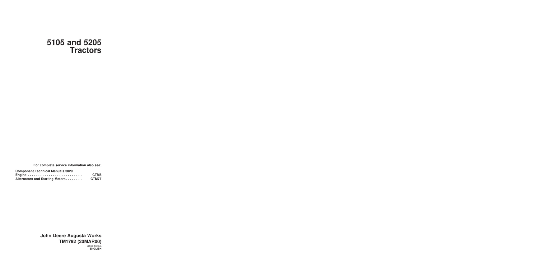
John Deere 5105 5205 Tractor Technical Manual TM1792 (2000) Repair & Tests PDF — PDF page 1 preview
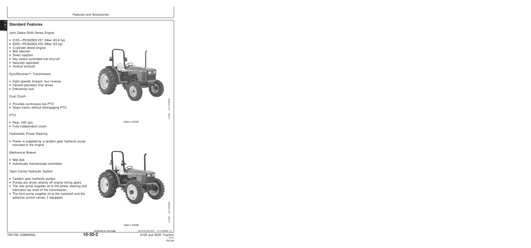
John Deere 5105 5205 Tractor Technical Manual TM1792 (2000) Repair & Tests PDF — PDF page 56 preview
John Deere 5105 5205 Tractor Technical Manual TM1792 (2000) Repair & Tests PDF — PDF page 118 preview

Capacities include a fuel tank of approximately 85.5 L (22.6 gal), cooling system of approximately 8.93 L (2.4 gal), crankcase with filter change of approximately 7.5 L (7.9 qt), SyncReverser transmission of approximately 33 L (8.7 gal), and MFWD axle and wheel hub capacities where equipped. Hydraulic system pressures, steering flow rates, implement flow rates, hitch lift capacity, torque values for major fasteners and the electrical system 12-volt negative ground specification with 700 CCA battery, 40 amp alternator and 12-volt starter motor are all listed.

Who This Manual Is For

This is a working manual for the experienced technician, the farm workshop, the repair shop and the owner who does their own servicing. It assumes familiarity with basic tools and safe working practice. Essential tools, service equipment, other materials and service parts kits are identified at the start of each group. Safety messages are carried through the text and signal words (DANGER, WARNING, CAUTION) are used with the safety-alert symbol.

Get Instant Access To The John Deere 5105 and 5205 Technical Manual TM1792

Everything you need to diagnose, service, repair and adjust a John Deere 5105 or 5205 tractor is in this one file. Instead of guessing at clearances, torque values or test sequences, you work from the manufacturer’s own procedures and specification tables. The complete repair and operation/test content for both models is covered in a single PDF, so you can search the section you need and print only the pages you want in the workshop.

Delivery is instant. After payment the PDF is available to download straight away. There is no shipping, no waiting for a parcel, and no restriction on which device you use to read it. Keep it on a laptop in the workshop, on a tablet next to the machine, or print the pages you need for the job at hand. Whether you are overhauling the engine, rebuilding the clutch, chasing an electrical fault, setting up the hydraulic system or just checking a specification before you start, the John Deere 5105 and 5205 Tractors Technical Manual TM1792 is the reference to keep within reach.
Reviews

There are no reviews yet.

Be the first to review “John Deere 5105 5205 Tractor Technical Manual TM1792 (2000) Repair & Tests PDF”

What Our Customers Say

★★★★★ Live reviews from customers
Loading customer reviews...
0
    0
    Your Cart
    Your cart is emptyReturn to Shop
    🛒
    Recently Purchased
    🕒 verified order