
John Deere 6105R 6115R 6125R 6130R 6140R 6150R 6170R 6190R 6210R Diagnosis & Tests Service Manual TM403819
Original price was: $94.95.$64.95Current price is: $64.95.
Comprehensive 6213-page John Deere Diagnosis and Tests Service Manual TM403819 for 6105R, 6115R, 6125R, 6130R, 6140R, 6150R, 6170R, 6190R and 6210R tractors. Covers diagnostic trouble codes, observable symptoms, system diagnosis, electrical and hydraulic schematics, operational checks, theory of operation, component information, tests, adjustments and special tools across major tractor systems.
Description
John Deere 6105R to 6210R Diagnosis and Tests Service Manual TM403819
This 6213-page John Deere 6105R 6115R 6125R 6130R 6140R 6150R 6170R 6190R 6210R Diagnosis & Tests Service Manual TM403819 is a detailed diagnostic technical reference for the listed John Deere tractors in the Worldwide Edition. Published as TM403819 in June 2013, it is organized around fault diagnosis, system checks, theory of operation, schematics, component identification, circuit testing and adjustment procedures rather than simply describing normal tractor operation.
The manual is intended for experienced technicians and is particularly strong where a fault must be traced logically instead of parts being replaced by trial and error. Its diagnostic structure connects symptoms and diagnostic trouble codes with electrical circuits, control units, sensors, connectors, hydraulic circuits and system tests. The manual itself explains that diagnostic technical manuals combine general information, checks, theory of operation, schematics and diagnostic procedures, with component sections showing the location of components and connectors.
File Details
- Manual type: Diagnosis and Tests Service Manual
- Brand: John Deere
- Models: 6105R, 6115R, 6125R, 6130R, 6140R, 6150R, 6170R, 6190R, 6210R
- Edition: Worldwide Edition
- Document number: TM403819
- Date: June 2013
- Language: English
- Pages: 6213
- File format: PDF
Built Around Real Diagnostic Work
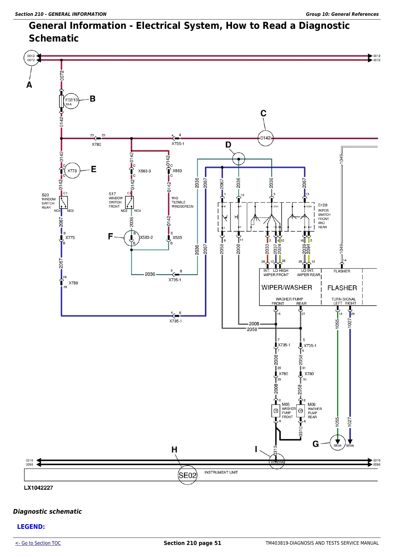
TM403819 goes far beyond a fault-code list. It provides a framework for moving from a reported symptom or stored code to a controlled test. Electrical troubleshooting guidance covers visual checks, connector problems, circuit and harness diagnosis, diagnostic schematics, lead numbers, wire color codes and the four basic circuit malfunction types: high resistance, open circuit, grounded circuit and shorted circuit. A seven-step electrical test procedure shows how voltage and continuity checks can be worked through systematically.
The document also contains extensive control-software diagnostics. Individual fault entries identify the condition that generates the diagnostic trouble code, the control-software reaction and the checks to perform next. Examples throughout the manual include supply-voltage faults, sensor-supply problems, control-software errors, switch and potentiometer faults, transmission-related signals, hitch controls, AutoTrac functions, engine sensors, fuel-system signals, exhaust aftertreatment and numerous other electronically controlled functions.
For hydraulic and mechanical diagnosis, the manual combines operational checks with pressure testing, specifications, hydraulic diagrams and theory of operation. Test sequences repeatedly instruct the technician to establish correct preconditions, take measurements and compare the result against a stated specification before proceeding to the next diagnostic step.
Chapters Covered
- Section 210 – GENERAL INFORMATION
- Section 211 – DIAGNOSTIC TROUBLE CODES
- Section 212 – OBSERVABLE SYMPTOMS AND SYSTEM DIAGNOSIS
- Section 220 – ENGINE
- Section 230 – FUEL, AIR INTAKE AND COOLING SYSTEMS
- Section 239 – FUEL, AIR INTAKE, AND COOLING SYSTEMS – COMPONENT INFORMATION
- Section 240 – ELECTRICAL SYSTEM
- Section 245 – ELECTRONIC CONTROL UNITS
- Section 249 – ELECTRICAL CONNECTORS, WIRING HARNESSES AND COMPONENTS
- Section 250A – DRIVE TRAIN (WITHOUT TRANSMISSION)
- Section 250B – AUTOPOWR™/IVT™ TRANSMISSION
- Section 250C – POWRQUAD™ TRANSMISSION
- Section 259 – DRIVE TRAIN – COMPONENT INFORMATION
- Section 260A – STEERING
- Section 260B – BRAKES
- Section 269 – STEERING AND BRAKES – COMPONENT INFORMATION
- Section 270 – HYDRAULIC SYSTEM
- Section 279 – HYDRAULIC SYSTEM – COMPONENT INFORMATION
- Section 280A – MACHINE-SPECIFIC SYSTEMS
- Section 280B – SUSPENSION SYSTEMS
- Section 289 – MACHINE-SPECIFIC SYSTEMS AND SUSPENSION SYSTEMS – COMPONENT INFORMATION
- Section 290 – OPERATOR’S CAB
- Section 300 – SPECIAL TOOLS
General Information and Diagnostic Foundations
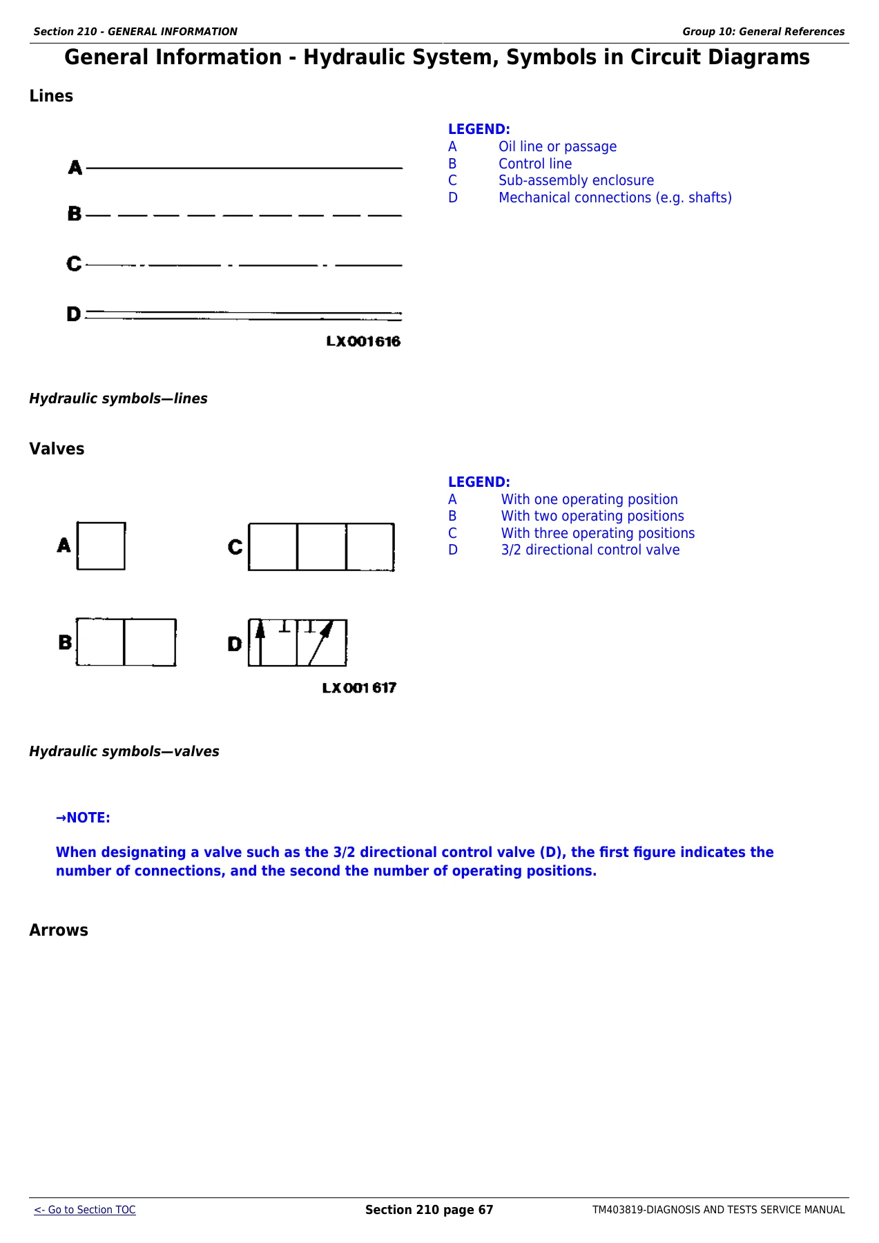
Section 210 establishes the diagnostic groundwork used throughout the John Deere TM403819 manual. Along with extensive safety information, it contains hydraulic and electrical designators, inch and metric fastener torque tables, hydraulic fitting torque tables and detailed instructions for interpreting diagnostic schematics. The electrical references explain component identification, lead numbering, wire-color conventions, connector inspection, tabular diagnostic procedures, intermittent-fault troubleshooting, circuit and harness testing and systematic visual checks. Hydraulic symbol references explain lines, valves, actuators, pumps, cylinders, reservoirs, sensors, test ports and other circuit-diagram symbols.
Diagnostic Trouble Codes
Section 211 is a major part of this manual and contains diagnostics for numerous tractor control software groups. The coverage includes AIC, ATC, CCU, CLC, CSC, CRU, CSM, ECU, EIC, ETC, FCC, HCC, JDL, OIC, PDU, PLC, PTA, PTF, PTQ, RLC, RPT, SCC, SCO, SFA, SMV, TEC, TEI, TIA, TIQ, VLC, VTI, XMC and XSC control software. Individual entries can provide the fault description, system response and a step-by-step path through code verification, operational checks, circuit tests, component checks, calibration or programming-related procedures where applicable.
Observable Symptoms and System Diagnosis
Section 212 approaches troubleshooting from the symptom side rather than only from stored codes. Major diagnostic groups cover the engine; fuel, air intake and cooling; electrical system; electronic control units; drive train; AutoPowr™/IVT™ and PowrQuad™ transmissions; steering; brakes; hydraulics; machine-specific functions; suspension systems; and the operator’s cab. This makes the manual useful when a tractor has a real operating complaint but the initial cause is not obvious. The electrical examples, for instance, guide diagnosis of starting and charging problems through preliminary checks, relevant schematics, components, harnesses, connectors and ground points.
Engine, Fuel, Air Intake and Cooling Diagnosis
The engine section includes exhaust aftertreatment theory of operation plus tests and adjustments. Fuel, air-intake and cooling coverage expands into fuel-system theory, air-intake theory, cooling-system theory, the charge-air circuit and cold-weather starting. Schematics and tests are supported by separate component-information coverage. The ECU diagnostic material also reaches deeply into engine-related signals and faults, including fuel pressure, engine oil pressure, crankcase pressure, manifold pressure and temperature, coolant conditions, injector circuits, camshaft and crankshaft speed signals, turbocharger controls, EGR functions, sensor supplies and exhaust-filter-related diagnostics.
Electrical Systems, Control Units and Wiring
Electrical diagnosis is one of the strongest areas of this John Deere 6105R-6210R service manual. Section 240 includes diagnostic schematics and circuit tests for systems such as starting and charging, lights, operator-seat functions, alarms, wipers, HVAC, power outlets, radio, electrical mirrors, accessories, TEC and ISOBUS, AutoTrac™, radar, JDLink™/Service ADVISOR™ Remote, electronic engine control, immobilizer, transmission controls, differential lock, front-wheel drive, PTO systems, brakes, rear hitch, selective and independent control valves, suspended MFWD axle, cab suspension, electro-hydraulic pick-up hitch, front end loader, display functions, cab switch module, reversing camera, CAN BUS systems and ground connections.
Section 245 complements that circuit-level coverage with electronic control-unit information, interactive tests and calibrations, programming information, theory of operation, component information and control-unit tests. Section 249 then provides the physical component and harness reference needed to relate a schematic to the tractor itself, covering assemblies, sensors, protective devices, relays, motors, switches, diodes, harnesses, connector ranges, contacts, ground points, solenoid valves and related electrical hardware.
Drive Train, AutoPowr™/IVT™ and PowrQuad™ Transmission
The drive-train material separates non-transmission systems from the two transmission families covered in dedicated sections. Drive Train without Transmission includes operational checks, theory of operation, tests and adjustments. AutoPowr™/IVT™ coverage contains general information, operational checks, theory of operation, hydraulic diagrams and tests and adjustments. PowrQuad™ coverage likewise includes general information, operational checks, theory, electrical system diagrams and test procedures.
These sections use measured test results rather than vague symptom descriptions. One drive-train diagnostic sequence, for example, calls for checking hydraulic oil temperature, system pressure and front-wheel-drive pressure before advancing through the troubleshooting path. Dedicated component-information groups support the drive train and both transmission types.
Steering and Brakes
Steering and brake systems receive separate diagnostic sections with general information, operational checks, theory of operation and tests and adjustments. Brake coverage also includes electrical system diagrams. Separate steering and brake component-information groups help identify the hardware associated with the checks and circuits.
Hydraulic System
Section 270 provides a substantial treatment of the tractor hydraulic system. It begins with general information and operational checks, then explains system theory and individual areas including the oil filter, additional oil reservoir, charge pump and hydraulic pump, rear hitch, front hitch, Selective Control Valves (SCVs) and Independent Control Valves (ICVs). Electrical system diagrams and tests and adjustments follow, with Section 279 supplying corresponding hydraulic component information.
This is valuable when diagnosing a function that may involve both hydraulic and electronic control. Rather than treating pressure, valves, sensors and electrical commands as unrelated subjects, the manual provides the references needed to test the system in a defined sequence.
Machine-Specific Systems, Suspension and Operator’s Cab
Machine-specific systems are covered through operational checks, theory of operation, electrical system diagrams and tests and adjustments. Suspension diagnosis includes the suspended front-wheel-drive axle and cab suspension, with theory, electrical diagrams and adjustment procedures. Separate component-information coverage supports both suspension and other machine-specific functions. The operator’s cab section follows the same practical diagnostic approach with operational checks, theory of operation and tests and adjustments.
Special Tools
Section 300 identifies special tools referenced by diagnostic procedures. The foreword specifically notes that essential tools required for certain work are identified in this section. Elsewhere in the manual, individual tests specify equipment such as multimeters and flexible test probes when those tools are required for a particular electrical check.
Diagnose the Fault Before Replacing Parts
For a technician working on a 6105R, 6115R, 6125R, 6130R, 6140R, 6150R, 6170R, 6190R or 6210R, this John Deere Diagnosis and Tests manual provides the information needed to move from symptoms and fault codes to measured, system-specific checks. Its combination of DTC procedures, operational checks, theory of operation, wiring and hydraulic diagrams, connector information, control-unit tests, component references, pressure checks and adjustment data helps isolate electrical, electronic, hydraulic, transmission and machine-system faults with far more confidence than guesswork.
IMAGES PREVIEW
Correct diagnosis matters on a tractor with interconnected control units, sensors, wiring, hydraulic circuits and electronically controlled functions. Following the specified test sequence and comparing results with the manual’s stated values can help identify the actual fault before unnecessary components are replaced. After purchase, the complete John Deere TM403819 Diagnosis and Tests Service Manual is supplied as an instant PDF download. There is no physical shipping delay: open it on a compatible computer, tablet or phone and print the pages you need for workshop use.
Reviews
There are no reviews yet.