★ TRUSTED BY 321,897+ PROFESSIONALS WORLDWIDE
🏢
Trusted Business
Verified & Licensed
🛡️
Virus Free Files
100% Safe Downloads
🔒
Secure Payment
SSL Protected
⚡
Instant Delivery
Available Immediately
Sale!

Landini Rex 70GT 80GT 90F/GT 100F/GT Deltashift Training Manual – Transmission, Hydraulic & Electrical Service Guide

Original price was: $39.95.Current price is: $24.95.

Landini Rex Deltashift training manual covering transmission, hydraulic circuit, electrical system, calibration and troubleshooting for 70GT, 80GT, 90F/GT and 100F/GT tractors. 491-page PDF with assembly drawings, wiring diagrams, torque values and step-by-step service procedures.

⚡
Instant PDF Download
Available immediately
💾
Save to Your Device
Download & keep forever
🛡️
Antivirus Scanned
100% virus-free
🌍
Trusted Worldwide
175,000+ customers

Description

Landini Rex Deltashift Training Manual – P/N 3665258 M1

This training manual covers the Landini Rex Deltashift series tractors, specifically the 70GT, 80GT, 90F/GT and 100F/GT models equipped with the Deltashift transmission module. Published under part number 3665258 M1, it contains the technical specifications, mechanical and hydraulic layouts, wiring diagrams, and instructions for operating and adjusting these tractors. It is compiled for assistance technicians who have already completed the relevant training courses, and it works alongside the theoretical and practical explanations given by instructors.

This is a comprehensive technical document spanning 491 pages. It does not cover every disassembly procedure in exhaustive detail, but it gives clear instructions for operating and adjusting the various components of the Deltashift system, backed by detailed diagrams and specifications that a working technician needs on the shop floor.

File Details

  • Manual type: Training Manual
  • Brand: Landini
  • Models covered: Rex 70GT, 80GT, 90F/GT, 100F/GT Deltashift
  • Language: English
  • Page count: 491
  • File format: PDF
  • Document number: P/N 3665258 M1

Chapters Covered

  • Chapter 1 – Introduction:
    • Reading the manual
    • Tractor identification (chassis and engine serial numbers)
    • Working in safety (accident prevention, danger decals, safe tractor use)
    • Conversion tables (length, area, volume, weight, pressure, torque, temperature)
    • Sealants (Loctite types and practical advice)
    • Driving torques
    • General assembly instructions (seals, O-rings, bearings)
  • Chapter 2 – Transmission:
    • Deltashift module: introduction and purpose
    • Assembly drawing and main components
    • Control levers (gear, range, reverse shuttle, Park Lock)
    • Power train diagrams
    • Technical specifications, ground speed tables, driving torques and sealants
    • Disassembly, re-assembly and adjustments (engine-gearbox assembly, gearbox, 4WD housing, rear PTO)
    • Special tools
  • Chapter 3 – Hydraulic Circuit:
    • General hydraulic circuit and main components
    • Low pressure circuit and cooling/lubricating circuit
    • Functional hydraulic layouts
    • Main components: hydraulic pump, power steering, hydraulic power packs, control cover, solenoid valve blocks, lubrication valve, rear PTO brake cock
    • Operating pressure inspections and special tools
  • Chapter 4 – Electrical System:
    • Basic electrical concepts and symbols
    • Main wiring diagram (7 parts)
    • Technical specifications, relays and fuse holders
    • Wiring lines: battery-starter motor, front engine, dashboard, platform, rear
    • Main components: sensors, potentiometers, solenoid valves, switches, buttons, instrument, reverse shuttle lever, electronic control unit
  • Special Tools: Part numbers and usage for transmission, PTO and hydraulic service

What This Manual Gives the Technician

The Landini Rex Deltashift transmission is a modular system built around a 4-speed synchronized gearbox with three ranges (slow, standard, fast), a synchronized reverse shuttle, and an electrohydraulically engaged creeper. That architecture produces 40 forward and 12 reverse speeds. This manual explains how the Deltashift module fits into that driveline, how the hydraulic clutch assemblies are supplied and controlled, and how the various options – underdrive, direct drive, overdrive and reverse – are engaged and disengaged.

On the hydraulic side, the manual breaks down the low pressure circuit, the cooling and lubrication circuit, and the hydraulic power packs that feed the Deltashift clutches, PTO brake, differential lock, 4WD disengagement and creeper. Pressure test procedures are included so you can verify calibration valve settings and diagnose faults rather than replacing parts on guesswork.

The electrical section covers the tractor’s wiring in detail, including connector locations, wire colours, and the functional wiring diagram broken into parts. Sensors, potentiometers, solenoid valves and the electronic control unit are identified and their adjustment values given where applicable.

Complete PDF Bookmark Tree

Complete Bookmarks

The complete bookmarks in the “Landini Rex 70GT 80GT 90F/GT 100F/GT Deltashift Training Manual – Transmission, Hydraulic & Electrical Service Guide” are as follows:

REX DELTASHIFTp. 1
PREFACEp. 2
TABLE OF CONTENTSp. 3
Chap. 1 INTRODUCTIONp. 4
Sect. 1 Reading the manualp. 6
1-1 Introductionp. 7
1-2 Structure of the manualp. 7
Sect. 2 Tractor identificationp. 8
2-1 Tractor identificationp. 9
2-2 Weights and dimensionsp. 10
Sect. 3 Working in safetyp. 12
3-1 Essential rules for accident preventionp. 13
3-2 Danger decalsp. 19
3-3 Replacement of tractor partsp. 22
3-4 Safe use of the tractorp. 22
Sect. 4 Conversion tablesp. 24
4-1 Lengthp. 25
4-2 Areap. 28
4-3 Volumep. 29
4-4 Weightp. 32
4-5 Pressurep. 34
4-6 Moment of rotationp. 36
4-7 Temperaturep. 38
Sect. 5 Sealantsp. 40
5-1 Types of Loctite sealantp. 41
5-2 Practical advicep. 42
Sect. 6 Driving torquesp. 44
Sect. 6 Driving torquesp. 45
Sect. 7 General assembly instructionsp. 46
7-1 Sealsp. 47
7-2 O-Ring sealsp. 48
7-3 Bearingsp. 49
Chap. 2 TRANSMISSIONp. 52
Precautions and Safety Recommendationsp. 53
Sect.1 General descriptionp. 54
1-1 Introduction to the Deltashift modulep. 56
1-2 Assembly drawing, main assemblies and description of operationp. 57
1-3 Control leversp. 61
1-4 Power train diagramsp. 63
Sect.2 Technical specificationsp. 66
2-1 Main technical specificationsp. 67
2-2 Ground speed tablep. 68
2-3 Driving torques and sealantsp. 69
Sect.3 Guide lines for disassembly, re-assembly and adjustmentsp. 72
A – Engine-gearbox assemblyp. 74
A1 – Assembly drawing and main componentsp. 75
A2 – Description of operationp. 77
A3 – Guide lines for disassemblyp. 85
A4 – Guide lines for re-assembly and inspectionsp. 94
B – Gearboxp. 100
B1 – Assembly drawing and main componentsp. 101
B2 – Guide lines for the inspectionsp. 102
C – 4WD housingp. 104
C1 – Assembly drawing and main componentsp. 105
C2 – Description of operationp. 106
C3 – Park Lockp. 107
C4 – Guide lines for disassemblyp. 110
C5 – Guide lines for re-assembly and inspectionsp. 113
D – Rear Power take-offp. 116
D1 -Assembly drawing and main componentsp. 117
D2 -Description of operationp. 118
D3 -Description of the controlsp. 122
D4 -Guide lines for disassemblyp. 123
D5 -Guide lines for the inspections, adjustments and re-assemblyp. 126
Sect.4 Special toolsp. 130
Sect. 4 Special toolsp. 131
Chap. 3 HYDRAULIC CIRCUITp. 134
Precautions and Safety Recommendationsp. 135
Sect. 1 General descriptionp. 136
1-1 General hydraulic circuit and main componentsp. 137
1-2 Description of the general circuitp. 139
1-3 Low pressure circuit and descriptionp. 141
1-4 Cooling, lubricating circuit and descriptionp. 143
1-5 Functional hydraulic layout (low pressure)p. 145
Sect. 2 Technical specificationsp. 146
2-1 Main technical specificationsp. 147
Sect. 3 Main components of the low pressure circuitp. 148
A – Hydraulic pumpp. 150
A1 – Main componentsp. 151
A2 – Description of operationp. 152
A3 – Splittingp. 153
A4 – Inspectionp. 153
A5 – Re-assembly and adjustmentp. 153
B – Power steering systemp. 154
B1 – Hydraulic circuitp. 155
B2 – Description of the circuit and functional diagramp. 156
B3 – Description of operationp. 158
B4 – Assembly drawing of the "Orbitrol" valve systemp. 161
B5 – Main components of the "Orbitrol" valve systemp. 162
C – Users' hydraulic power packp. 164
C1 – Main componentsp. 165
C2 – Description of operationp. 166
C3 – Functional diagramp. 167
C4 – 9.5 and 20 bar calibration valvesp. 168
C5 – Rear PTO brake oil supplyp. 169
D – Deltashift's hydraulic power packp. 176
D1 – Main componentsp. 177
D2 – Description of operationp. 178
D3 – Functional diagramp. 179
D4 – Reverse oil supplyp. 180
E – Deltashift's hydraulic clutch assembliesp. 182
E1 – General descriptionp. 183
E2 – Main components and description of operationp. 184
F – Control coverp. 186
F1 – Main componentsp. 187
F2 – General descriptionp. 188
F3 – Description of operationp. 189
G- Block for solenoid valves that control clutches and lubricationp. 192
G1 – Main components and positionsp. 193
G2 – Description of operationp. 194
G3 – Functional diagramp. 196
H – Block for forced lubrication valvep. 198
H1 – Main components and positionsp. 199
H2 – Functional diagramp. 200
H3 – Description of operationp. 201
I – Rear PTO brake fluid supply cockp. 204
I1 – General description and positionp. 205
I2 – Functional diagramp. 205
I3 – Description of operationp. 206
Sect. 4 How to inspect the operating pressure valuesp. 208
4-1 Introductionp. 209
4-2 Low pressure circuit pressure testsp. 209
Sect. 5 Special toolsp. 216
Sect. 5 Special toolsp. 217
Chap. 4 ELECTRICAL SYSTEMp. 220
Precautions and Safety Recommendationsp. 221
Sect.1 General descriptionp. 222
1-1 Basic conceptsp. 223
1-2 Electricity symbolsp. 232
1-3 Main wiring diagramp. 240
Sect.2 Technical specificationsp. 248
2-1 Main technical specificationsp. 249
2-2 Relays and fuse holdersp. 250
Sect.3 Wiringp. 254
3-1 Introductionp. 255
3-2 General descriptionp. 257
3A – Battery-starter motor linep. 260
3A-1 General descriptionp. 261
3A-2 Wiringp. 262
3A-3 Connector locationsp. 263
3A-4 Connector identificationp. 264
3B – Front engine linep. 266
3B-1 General descriptionp. 267
3B-2 Connector locationsp. 268
3B-3 Wiringp. 269
3B-4 Multiple wiring diagramp. 270
3B-5 Connector identificationp. 271
3C- Dashboard linep. 278
3C-1 General descriptionp. 279
3C-2 Connector locationsp. 280
3C-3 Wiringp. 281
3C-4 Multiple wiring diagramp. 282
3C-5 Connector identificationp. 283
3D- Platform linep. 292
3D-1 General descriptionp. 293
3D-2 Connector locationsp. 294
3D-3 Wiringp. 295
3D-4 Multiple wiring diagramp. 296
3D-5 Connector identificationp. 297
3E – Rear linep. 308
3E-1 General descriptionp. 309
3E-2 Connector locationsp. 310
3E-3 Wiringp. 311
3E-4 Multiple wiring diagramp. 312
3E-5 Connector identificationp. 313
Sect.4 Main componentsp. 322
4-1 Introductionp. 323
4A – Sensors and potentiometersp. 324
4A-1 General descriptionp. 325
4A-2 Locationp. 327
4A-3 Identificationp. 328
4A-4 Adjustmentsp. 333
4B – Solenoid valvesp. 336
4B-1 General descriptionp. 337
4B-2 Locationsp. 339
4B-3 Identificationp. 340
4C – Switches and buttonsp. 348
4C-1 General descriptionp. 349
4C-2 Locationp. 350
4C-3 Identificationp. 351
4D – Instrumentp. 358
4D-1 Indicatorsp. 359
4D-2 Wiring diagramp. 363
4E – Reverse shuttle leverp. 366
4E-1 General descriptionp. 367
4E-2 Functionality testsp. 368
4F – Electronic control unitp. 370
4F-1 General descriptionp. 371
4F-2 Main technical specificationsp. 373
4F-3 Ledsp. 374
4F-4 Signals controlled by the processorp. 375
4F-5 Resistive Blockp. 377
Chap. 5 CHECK-CONTROL AND TROUBLESHOOTINGp. 380
Precautions and Safety recommendationsp. 381
Sect.1 Introductionp. 382
1-1 Check-control and troubleshootingp. 383
1-2 Conventional troubleshootingp. 384
Sect.2 Alarm codesp. 388
2-1 Safety notesp. 390
2-2 Alarm code autodiagnosisp. 391
Chap. 6 CALIBRATIONp. 450
Precautions and Safety Recommendationsp. 451
Sect. 1 Introductionp. 452
1-1 Introduction to calibrationp. 453
1-2 The components involvedp. 455
1-3 Main technical specificationsp. 458
Sect. 2 Calibration procedurep. 460
2-1 Safety notesp. 461
2-2 When to calibrate and in which conditionsp. 462
2-3 Calibrationp. 463
Chap. 7 SPECIAL TOOLSp. 476
Sect.1 Constructional drawingsp. 476
141 DS LGp. 478
143 DS LGp. 479
01 DF MYTp. 480
02 PTO MYTp. 481
02 DT MYTp. 482
122 IDR GLp. 485
123 IDR GLp. 486
03 IDR MISp. 487
03 IDR REXp. 488
04 IDR REXp. 489

Transmission service coverage includes removal and re-assembly of the Deltashift main shaft, transmission shaft, reverse shuttle shaft, control cover, 4WD housing and rear PTO clutch assembly. Inspection criteria for clutch discs, synchronizer rings, bearings and gears are provided, along with the special tools required for the job.

Why This Manual Matters for Landini Rex Deltashift Owners and Technicians

The Deltashift transmission is electronically controlled and hydraulically actuated. When something goes wrong – a clutch slipping, a range not engaging, the PTO brake not releasing, or a fault code appearing – the correct diagnosis depends on understanding how the system is supposed to behave and what the pressure and resistance values should be. This manual supplies those values: switch resistance readings, calibration pressures, torque settings, and adjustment clearances.

For the 70GT, 80GT, 90F/GT and 100F/GT models, that means you can approach a repair with the manufacturer’s own data rather than generic assumptions. The assembly drawings and exploded views help you identify part relationships and assembly order, while the torque and sealant tables help you reassemble components correctly.

Because this is a training manual, it assumes some prior familiarity with the tractor range. It is not a complete tear-down guide for every nut and bolt, but it is a strong companion for anyone doing transmission, hydraulic or electrical work on these Deltashift tractors, especially when combined with the practical instruction the original training course provided.

Get the Landini Rex Deltashift Training Manual

IMAGES PREVIEW

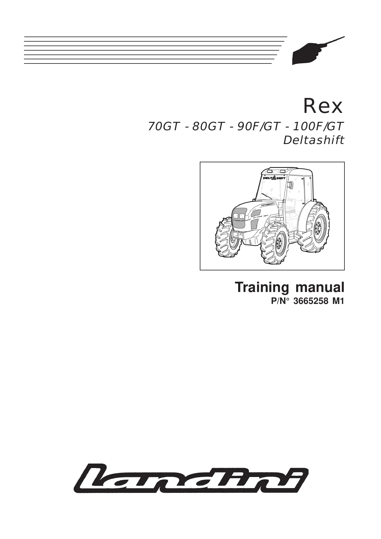
Landini Rex 70GT 80GT 90F/GT 100F/GT Deltashift Training Manual - Transmission, Hydraulic & Electrical Service Guide — PDF page 1 preview
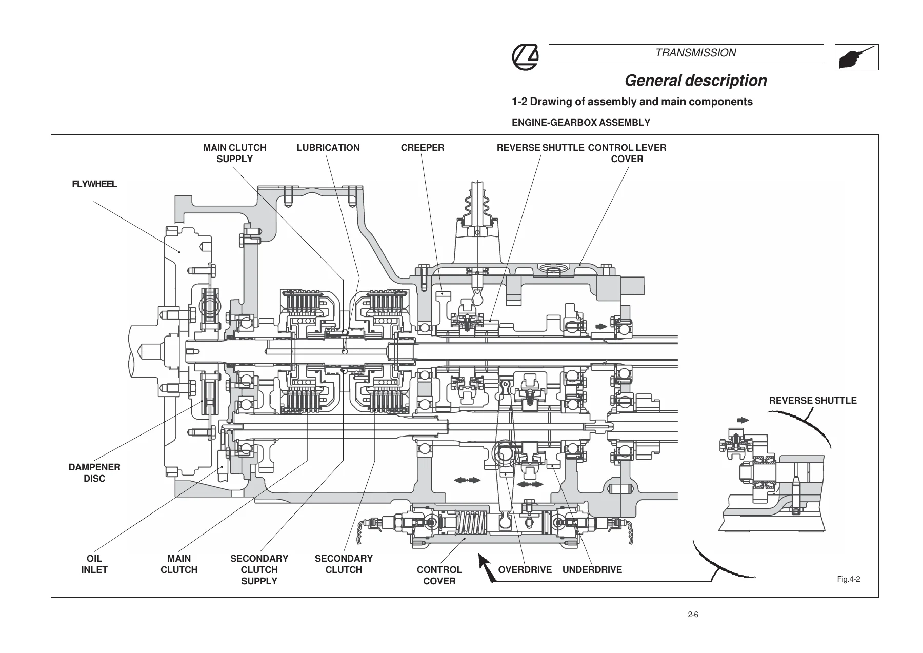
Landini Rex 70GT 80GT 90F/GT 100F/GT Deltashift Training Manual - Transmission, Hydraulic & Electrical Service Guide — PDF page 57 preview
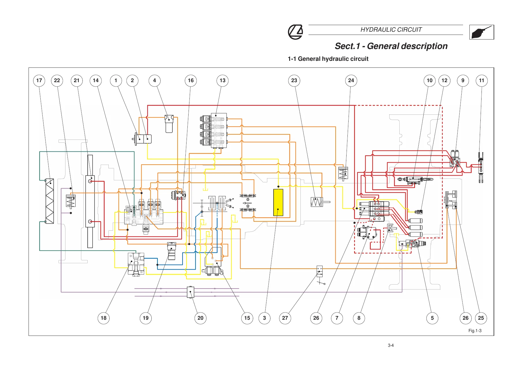
Landini Rex 70GT 80GT 90F/GT 100F/GT Deltashift Training Manual - Transmission, Hydraulic & Electrical Service Guide — PDF page 137 preview

This Landini Rex 70GT 80GT 90F/GT 100F/GT Deltashift training manual is delivered as an instant PDF download, so there is no shipping and no waiting for a physical book. You can open it on a laptop, tablet or phone in the workshop, search through the sections you need, and print the pages you want to keep by the machine.

If you maintain, repair or service a Rex Deltashift tractor, this manual gives you the specifications, diagrams and procedures to do the job with the right information in front of you.

Reviews

There are no reviews yet.

Be the first to review “Landini Rex 70GT 80GT 90F/GT 100F/GT Deltashift Training Manual – Transmission, Hydraulic & Electrical Service Guide”

What Our Customers Say

★★★★★ Live reviews from customers
Loading customer reviews...
0
    0
    Your Cart
    Your cart is emptyReturn to Shop
    🛒
    Recently Purchased
    🕒 verified order