★ TRUSTED BY 321,897+ PROFESSIONALS WORLDWIDE
🏢
Trusted Business
Verified & Licensed
🛡️
Virus Free Files
100% Safe Downloads
🔒
Secure Payment
SSL Protected
Instant Delivery
Available Immediately
Sale!

Kubota M130X Tractor Workshop Manual – 2010 Full Service Repair PDF

Original price was: $39.95.Current price is: $23.95.

The complete February 2010 Kubota M130X Tractor Workshop Manual (Code No. 9Y111-04470) in PDF form. Covers engine, clutch, transmission, rear axle, brakes, front axle, steering, hydraulics, electrical system and cabin for the M130X tractor.

SKU: KUB-M130X-WSM-9Y111-04470-HD Category: Tags: , , , Vendor: ToolboxManuals
Instant PDF Download
Available immediately
💾
Save to Your Device
Download & keep forever
🛡️
Antivirus Scanned
100% virus-free
🌍
Trusted Worldwide
175,000+ customers

Description

File Details

  • Manual type: Tractor workshop manual – full service, repair, maintenance and diagnostics
  • Brand: Kubota
  • Model: M130X
  • Language: English
  • Page count: Approximately 652 pages
  • File format: PDF
  • Document number: 9Y111-04470
  • Publication date: February 2010
  • Document structure: Information, General, Mechanism, Servicing

Chapters Covered

  • Information – Safety First, Safety Decals, Specifications, Traveling Speeds, Dimensions
  • General – Tractor Identification (Model Name and Serial Number, E3 Engine Identification, Cylinder Number), General Precautions, Handling Precautions for Electrical Parts and Wiring, Lubricants Fuel and Coolant, Tightening Torques, Maintenance, Check and Maintenance Intervals, Special Tools, Tires, Implement Limitations
  • Engine – Feature, Engine Body (Cylinder Block, Center Direct Injection System, Piston, Balancer), Lubricating System (Oil Cooler), Cooling System (Thermostat, Bottom Bypass System), Intake and Exhaust System, Common Rail System (CRS), Exhaust Gas Recirculation (EGR) System
  • Clutch – Traveling Clutch, Master Clutch (Forward and Reverse), Clutch Safety Valve, Master Clutch Control System, PTO Clutch
  • Transmission – Structure, Power Shift System, Construction and Function of Components, Electric Control System, Auto Speed Control, Down-hill Control, Clutch Pedal Control, Shuttle Control, Auxiliary Control, Hydraulic Control System
  • Rear Axle – Structure, Planetary Gear Support, Rear Axle Cover, Backlash, Thrust Collar, Servicing Specifications
  • Brakes – Traveling Brake, Master Cylinder and Equalizer, Brake Case, Parking Brake
  • Front Axle – Structure, Bevel Gear Case Assembly, Front Differential Assembly, Spiral Bevel Pinion Shaft, Servicing Specifications
  • Steering – Steering Mechanism, Full Hydrostatic Power Steering, Steering Controller, Steering Cylinder
  • Hydraulic System – Structure, Hydraulic Circuit, PTO Clutch Valve, Regulator Valve, Power Shift Valve, Clutch Safety Valve, Three Point Hitch System, 3-Point Hitch Control System, Control Valve, Cylinder Safety Valve
  • Electrical System – Electrical Circuit Detailed Chart, Power Shift Control, Digital LCD Monitor, 3-Point Hitch Control, Starting System, PTC Heater, Meter Panel, OPC (Operator Presence Control), CAN Communication
  • Cabin – Air Conditioning System, Compressor, System Control, Electrical System, Air Suspension Seat System, Height Level Control, Horizontal Spring Unit

The Kubota M130X Tractor Workshop Manual released in February 2010 under document number 9Y111-04470 is the full dealer-scale service document for the M130X tractor platform. It is organised into four master parts – Information, General, Mechanism and Servicing – and works through every major system on the machine: the V6108 four-cylinder common rail turbo diesel, the shuttle master clutch, the 16-speed power shift transmission, the rear axle final drive, wet disc brakes, the front axle with differential gear lock, full hydrostatic power steering, the 3-point hitch and auxiliary hydraulics, the power shift and 3-point hitch electrical control systems, and the cabin air conditioning and air suspension seat. The Mechanism chapters explain how each system is built and how it behaves in service, then the Servicing chapters follow with troubleshooting tables, servicing specifications, tightening torques, and step-by-step checking, disassembling and assembling procedures.

IMAGES PREVIEW

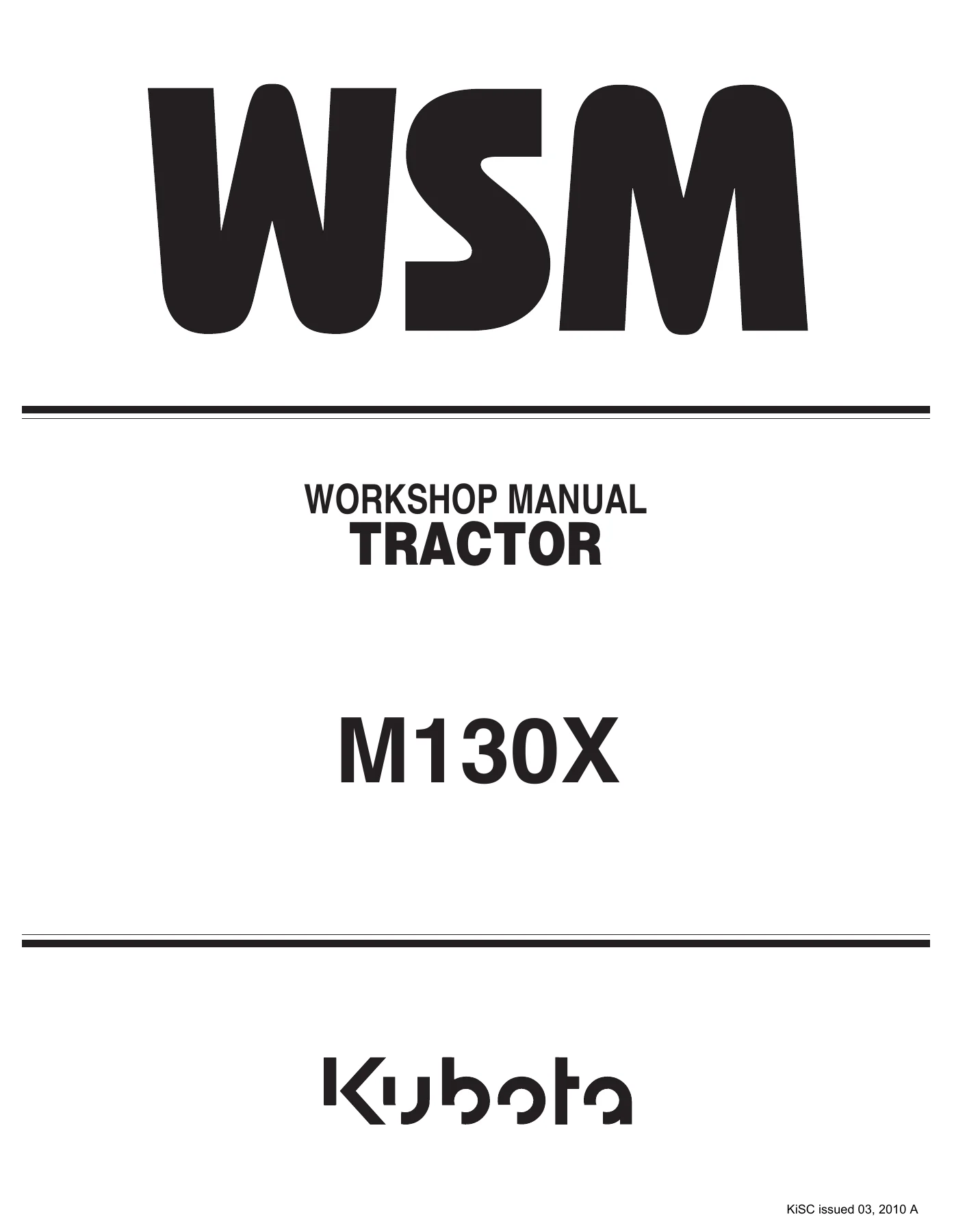
Kubota M130X Tractor Workshop Manual - 2010 Full Service Repair PDF — PDF page 1 preview
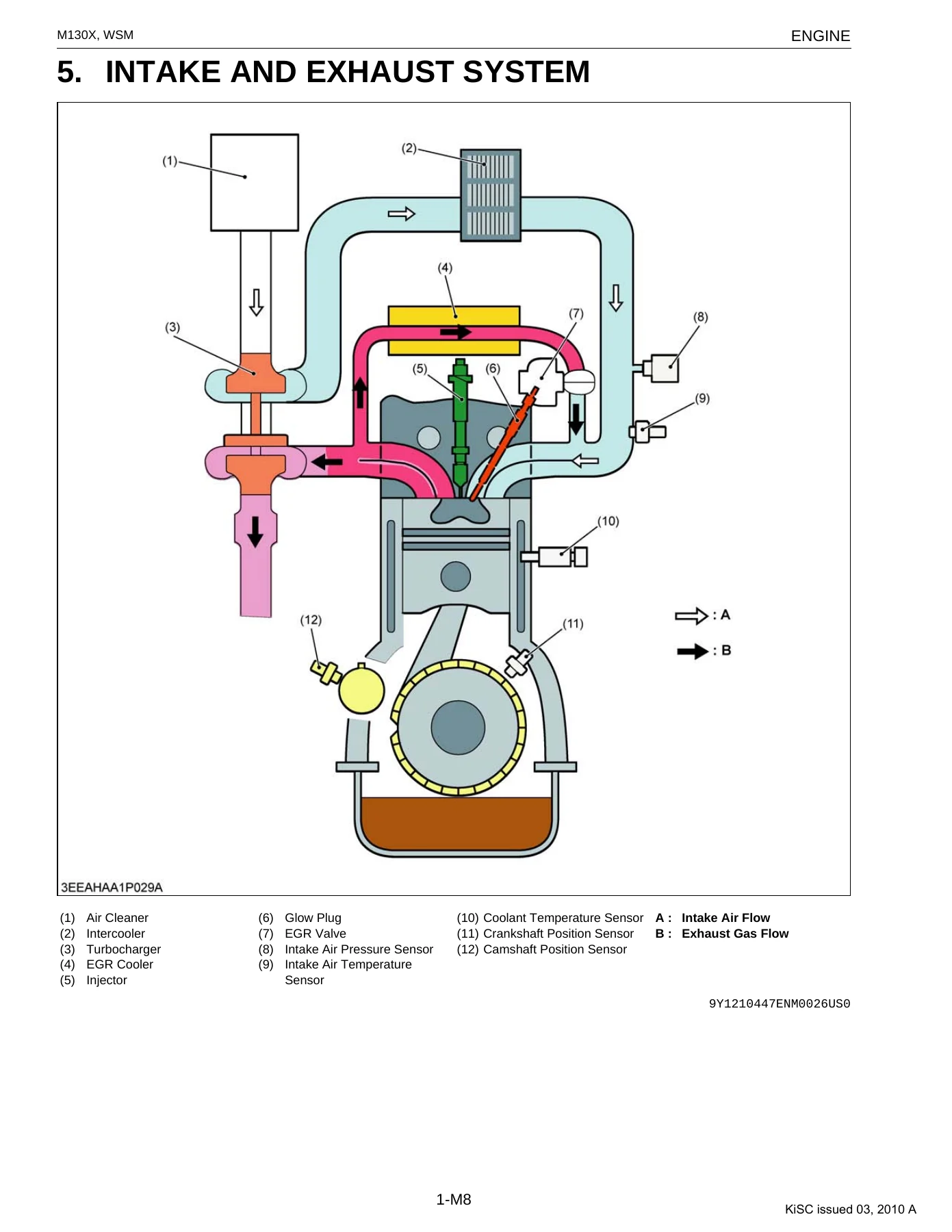
Kubota M130X Tractor Workshop Manual - 2010 Full Service Repair PDF — PDF page 107 preview
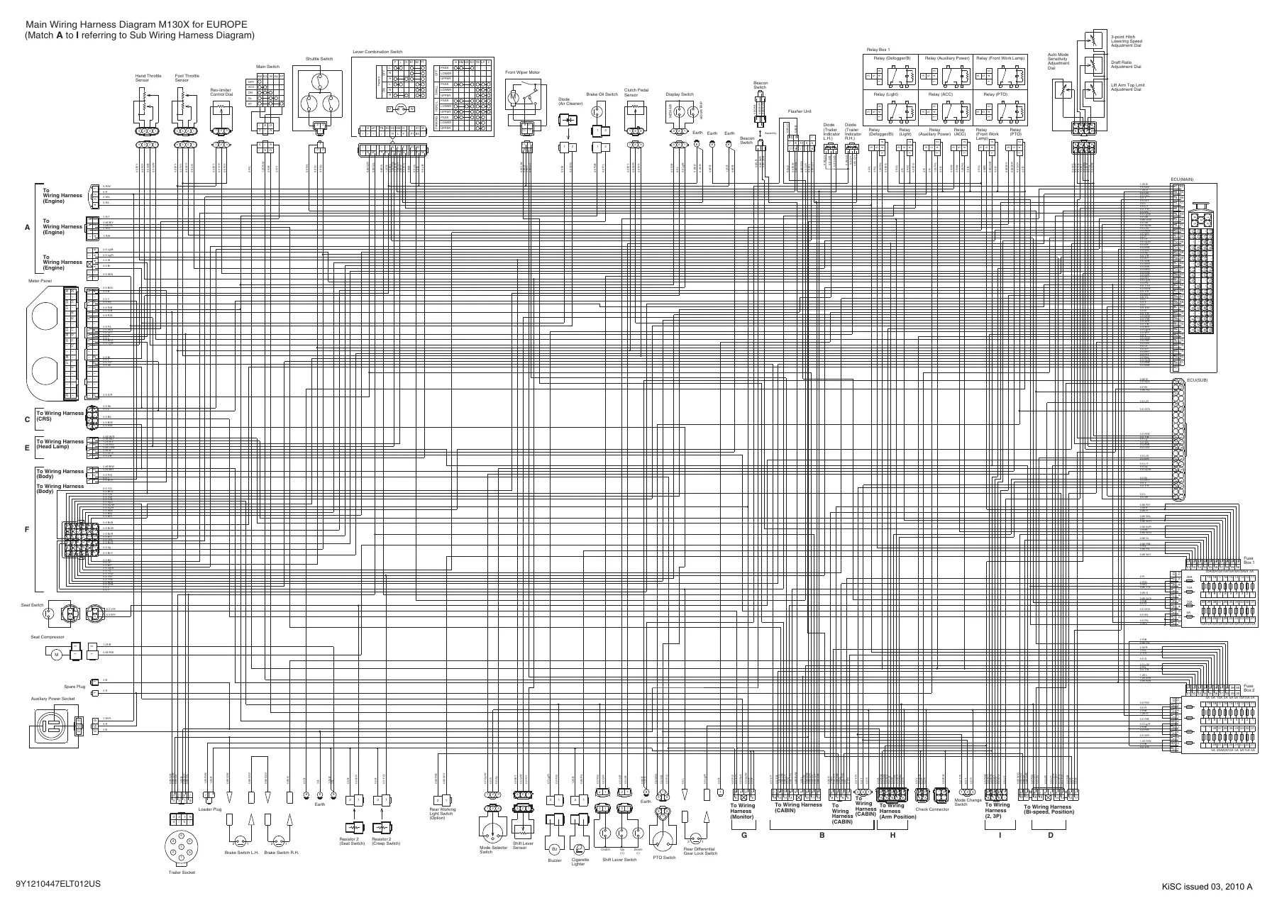
Kubota M130X Tractor Workshop Manual - 2010 Full Service Repair PDF — PDF page 650 preview

What This Workshop Manual Covers

The Mechanism half of the manual is not a parts catalogue – it is a functional breakdown. The engine section explains the ladder-frame crankcase design, the Center Direct Injection System (E-CDIS), the coolant-cooled oil cooler, the bottom bypass cooling layout, the common rail supply pump with SCV, the rail and pressure limiter, the injector with QR code correction data, the engine ECU, the sensors, and the EGR valve, reed valve and EGR cooler. The transmission section explains how the main shift clutches (1-2, 3-4 and L-H) and the master clutch are switched hydraulically by the power shift valve assembly, how the auto-mode travel and field control logic works, and how the hydraulic circuit is fed from the regulator valve.

The Servicing half is where the repair work lives. Every major system has a troubleshooting chart listing symptom, probable cause, solution and reference page, followed by a servicing specification table, a tightening torque table, and detailed checking / disassembling / servicing procedures with disassembly order, inspection limits, adjustment values, and reassembly notes.

Mechanical, Hydraulic and Electrical Coverage

  • Engine mechanical – cylinder block, cylinder head, pistons, connecting rods, crankshaft, camshaft, timing gears, balancer shafts, valve train, valve clearance
  • Common Rail System – supply pump, SCV, rail, pressure limiter, rail pressure sensor, injectors, engine ECU, crankshaft and camshaft position sensors, intake air pressure and temperature sensors
  • Exhaust Gas Recirculation – EGR valve with brush-type DC motor and lift sensor, EGR cooler, reed valve
  • Cooling system – thermostat with bottom bypass, water pump, oil cooler
  • Lubrication – trochoid oil pump, relief valve, oil cooler lines
  • Traveling clutch – forward/reverse hydraulic master clutch, clutch pedal sensor, clutch safety valve, shuttle rotation sensor
  • PTO clutch – solenoid valve, accumulator, wet multi-plate clutch pack, brake ring
  • Power shift transmission – 16 forward/16 reverse speed structure (8 main + L/H range), creep option, 4WD and bi-speed clutch packs
  • Differential and rear axle – spiral bevel gear set, side gears, pinion shafts, planetary final drive, differential gear lock
  • Brakes – hydraulic wet disc traveling brake, master cylinder, equalizer, brake case, parking brake with cam and pads
  • Front axle – bevel gear case, front differential, differential gear lock piston, turning angle inspection switch
  • Steering – full hydrostatic power steering, steering controller, steering cylinder, relief valve
  • Hydraulics – 3-point hitch control valve, regulator valve, power shift valve assembly, PTO clutch valve, cylinder safety valve, auxiliary control valve, lower link, lift arm, draft sensor
  • Electrical – power shift control system, instrument panel with Easy Checker lamps, digital LCD monitor, starting and charging system, PTC glow heater, OPC system, CAN bus, and the full Main and Sub Wiring Harness Diagrams for Europe
  • Cabin – air conditioning system with vane compressor, receiver, condenser, pressure switch and heater hoses; air suspension seat with compressor, pneumatic spring, height level control unit and cam switch

Complete PDF Bookmark Tree

Complete Bookmarks

The complete bookmarks in the “Kubota M130X Tractor Workshop Manual – 2010 Full Service Repair PDF” are as follows:

M130Xp. 1
TO THE READERp. 2
I INFORMATIONp. 3
INFORMATIONp. 4
1. SAFETY FIRSTp. 5
2. SAFETY DECALSp. 8
3. SPECIFICATIONSp. 13
4. TRAVELING SPEEDSp. 14
5. DIMENSIONSp. 15
G GENERALp. 16
GENERALp. 17
1. TRACTOR IDENTIFICATIONp. 18
[1] MODEL NAME AND SERIAL NUMBERp. 18
[2] E3 ENGINEp. 20
[3] CYLINDER NUMBERp. 20
2. GENERAL PRECAUTIONSp. 21
3. HANDLING PRECAUTIONS FOR ELECTRICAL PARTS AND WIRINGp. 22
[1] WIRINGp. 22
[2] BATTERYp. 24
[3] FUSEp. 24
[4] CONNECTORp. 24
[5] HANDLING OF CIRCUIT TESTERp. 25
[6] COLOR OF WIRINGp. 26
4. LUBRICANTS, FUEL AND COOLANTp. 27
5. TIGHTENING TORQUESp. 30
[1] GENERAL USE SCREWS, BOLTS AND NUTSp. 30
[2] STUD BOLTSp. 30
[3] HYDRAULIC FITTINGSp. 31
(1) Hydraulic Hose Fittingsp. 31
(2) Hydraulic Pipe Cap Nutsp. 31
(3) Adaptors, Elbows and Nutsp. 31
6. MAINTENANCEp. 32
7. CHECK AND MAINTENANCEp. 35
[1] DAILY CHECKp. 35
[2] CHECK POINTS OF INITIAL 50 HOURSp. 36
[3] CHECK POINTS OF EVERY 50 HOURSp. 38
[4] CHECK POINTS OF EVERY 100 HOURSp. 40
[5] CHECK POINTS OF EVERY 200 HOURSp. 46
[6] CHECK POINTS OF EVERY 300 HOURSp. 48
[7] CHECK POINTS OF EVERY 400 HOURSp. 49
[8] CHECK POINTS OF EVERY 600 HOURSp. 51
[9] CHECK POINT OF EVERY 800 HOURSp. 53
[10] CHECK POINT OF EVERY 1500 HOURSp. 53
[11] CHECK POINTS OF EVERY 3000 HOURSp. 53
[12] CHECK POINTS OF EVERY 1 YEARp. 53
[13] CHECK POINTS OF EVERY 2 YEARSp. 54
[14] OTHERSp. 57
8. SPECIAL TOOLSp. 63
[1] SPECIAL TOOLS FOR ENGINEp. 63
[2] SPECIAL TOOLS FOR TRACTORp. 73
9. TIRESp. 85
[1] TYPE OF TIRESp. 85
[2] TREAD ADJUSTMENTp. 86
(1) Front Wheelp. 86
(2) Rear Wheelp. 88
[3] WHEEL HUBp. 89
[4] TIRE PRESSUREp. 89
[5] TIRE LIQUID INJECTIONp. 90
10. IMPLEMENT LIMITATIONSp. 93
1 ENGINEp. 98
MECHANISMp. 99
1. FEATUREp. 100
2. ENGINE BODYp. 101
[1] CYLINDER BLOCKp. 101
[2] CENTER DIRECT INJECTION SYSTEM (E-CDIS)p. 102
[3] PISTONp. 102
[4] BALANCERp. 102
3. LUBRICATING SYSTEMp. 103
[1] OIL COOLERp. 103
4. COOLING SYSTEMp. 104
[1] THERMOSTATp. 104
[2] BOTTOM BYPASS SYSTEMp. 106
5. INTAKE AND EXHAUST SYSTEMp. 107
6. COMMON RAIL SYSTEM (CRS)p. 108
[1] GENERALp. 108
(1) Fuel Systemp. 108
[2] SUPPLY PUMPp. 110
[3] RAILp. 113
[4] INJECTORp. 114
[5] ENGINE CONTROL SYSTEMp. 118
(1) Engine Control System Diagramp. 118
(2) Engine ECU (Electronic Control Unit)p. 119
(3) Sensorsp. 120
7. EXHAUST GAS RECIRCULATION (EGR) SYSTEMp. 125
[1] GENERALp. 125
[2] EGR VALVEp. 126
[3] REED VALVEp. 127
SERVICINGp. 128
1. TROUBLESHOOTINGp. 129
2. SERVICING SPECIFICATIONSp. 132
3. TIGHTENING TORQUESp. 137
4. CHECKING, DISASSEMBLING AND SERVICINGp. 139
[1] CHECKING AND ADJUSTINGp. 139
(1) Engine Bodyp. 139
(2) Lubricating Systemp. 141
(3) Cooling Systemp. 142
(4) Turbochargerp. 143
[2] PREPARATIONp. 144
(1) Separating Front Axle Support from Enginep. 144
(2) Separating Engine from Clutch Housingp. 149
[3] DISASSEMBLING AND ASSEMBLINGp. 152
(1) External Componentsp. 152
(2) Turbochargerp. 152
(3) Exhaust Gas Recirculation (EGR)p. 153
(4) Common Rail System (CRS)p. 154
(5) Cylinder Head and Valvesp. 158
(6) Thermostatp. 163
(7) Water Pump and Oil Coolerp. 164
(8) Front Coverp. 165
(9) Flywheel and Flywheel Housingp. 167
(10) Timing Gearp. 172
(11) Piston and Connecting Rodp. 173
(12) Crankshaft and Crankcasep. 176
[4] SERVICINGp. 177
(1) Cylinder Head and Valvesp. 177
(2) Timing Gearsp. 183
(3) Piston and Connecting Rodp. 188
(4) Crankshaftp. 191
(5) Cylinderp. 194
(6) Oil Pumpp. 195
2 CLUTCHp. 196
MECHANISMp. 197
1. TRAVELING CLUTCHp. 198
[1] STRUCTUREp. 198
(1) Master Clutch (Forward and Reverse)p. 198
(2) Clutch Safety Valvep. 199
[2] MASTER CLUTCH CONTROL SYSYEMp. 200
(1) Clutch Pedal Controlp. 200
(2) Master Clutch Protection Controlp. 200
(3) Machine Speed Check Controlp. 200
2. PTO CLUTCHp. 201
[1] STRUCTUREp. 201
SERVICINGp. 203
1. TROUBLESHOOTINGp. 204
2. SERVICING SPECIFICATIONSp. 205
3. TIGHTENING TORQUESp. 206
4. CHECKING, DISASSEMBLING AND SERVICINGp. 207
[1] PREPARATIONp. 207
(1) Removing Master Clutch Assembly and Damper Discp. 207
(2) Removing PTO Clutch Packp. 215
(3) Removing PTO Clutch Valvep. 226
[2] DISASSEMBLING AND ASSEMBLINGp. 227
(1) Master Clutchp. 227
(2) PTO Clutchp. 229
[3] SERVICINGp. 230
(1) Damper Discp. 230
(2) Master Clutchp. 230
(3) PTO Clutchp. 231
3 TRANSMISSIONp. 233
MECHANISMp. 234
1. STRUCTUREp. 235
2. POWER SHIFT SYSTEMp. 237
[1] CONSTRUCTION AND FUNCTION OF COMPONENTSp. 237
(1) Electrical Componentsp. 237
(2) Hydraulic Componentsp. 243
[2] ELECTRIC CONTROL SYSTEMp. 245
(1) Control Systemp. 245
(2) Power Shift Controlp. 247
[3] AUTO SPEED CONTROLp. 248
(1) Travel Modep. 248
(2) Field Modep. 250
[4] OTHER CONTROLp. 252
(1) Down-hill Controlp. 252
(2) Clutch Pedal Controlp. 252
(3) Shuttle Controlp. 252
(4) Auxiliary Controlp. 253
[5] HYDRAULIC CONTROL SYSTEMp. 254
(1) Hydraulic Circuitp. 254
SERVICINGp. 255
1. TROUBLESHOOTINGp. 256
[1] POWER SHIFT SYSTEMp. 256
(1) Indication of Trouble by Fail-safe Functionp. 256
(2) Except Fail-safe Functionp. 260
[2] TRANSMISSION AND DIFFERENTIAL GEARp. 261
2. SERVICING SPECIFICATIONSp. 262
3. TIGHTENING TORQUESp. 264
4. CHECKING, DISASSEMBLING AND SERVICINGp. 265
[1] CHECKING AND ADJUSTINGp. 265
[2] SEPARATIONp. 265
(1) Separating Engine from Clutch Housingp. 265
(2) Separating Clutch Housing from Transmission Casep. 272
(3) Separating Hydraulic Cylinder and Rear Axle from Transmission Casep. 273
(4) Separating Rear PTO Case from Transmission Casep. 273
(5) Removing Differential Gear Assembly and Pinion Shaftp. 274
[3] DISASSEMBLING AND ASSEMBLINGp. 277
(1) Clutch Housing Casep. 277
(2) Creep Gear Casep. 287
(3) Rear PTO Gear Casep. 288
(4) Differential Gearp. 289
(5) Differential Gear Lock Clutchp. 290
(6) Rear Drive Shaft (Parking Brake Shaft) and Parking Brakep. 291
[4] SERVICINGp. 292
(1) Bearing, Shift Fork and Synchronizerp. 292
(2) Main Shift Clutchp. 293
(3) 4WD/Bi-speed Clutchp. 295
(4) Differential Gearp. 296
4 REAR AXLEp. 301
MECHANISMp. 302
1. STRUCTUREp. 303
SERVICINGp. 304
1. TROUBLESHOOTINGp. 305
2. SERVICING SPECIFICATIONSp. 306
3. TIGHTENING TORQUESp. 307
4. CHECKING, DISASSEMBLING AND SERVICINGp. 308
[1] PREPARATIONp. 308
(1) Separating Rear Axle Case from Transmission Casep. 308
[2] DISASSEMBLING AND ASSEMBLINGp. 310
(1) Rear Axle Casep. 310
[3] SERVICINGp. 311
5 BRAKESp. 312
MECHANISMp. 313
1. STRUCTUREp. 314
SERVICINGp. 315
1. TROUBLESHOOTINGp. 316
2. SERVICING SPECIFICATIONSp. 317
3. TIGHTENING TORQUESp. 318
4. CHECKING, DISASSEMBLING AND SERVICINGp. 319
[1] CHECKING AND ADJUSTINGp. 319
[2] DISASSEMBLING AND ASSEMBLINGp. 322
(1) Master Cylinder and Equalizerp. 322
(2) Brake Casep. 325
(3) Parking Brakep. 328
[3] SERVICINGp. 328
6 FRONT AXLEp. 330
MECHANISMp. 331
1. STRUCTUREp. 332
SERVICINGp. 333
1. TROUBLESHOOTINGp. 334
2. SERVICING SPECIFICATIONSp. 335
3. TIGHTENING TORQUESp. 337
4. CHECKING, DISASSEMBLING AND SERVICINGp. 338
[1] CHECKING AND ADJUSTINGp. 338
[2] PREPARATIONp. 340
(1) Separating Front Axlep. 340
[3] DISASSEMBLING AND ASSEMBLINGp. 345
(1) Bevel Gear Case Assemblyp. 345
(2) Front Differential Assemblyp. 348
[4] SERVICINGp. 351
7 STEERINGp. 358
MECHANISMp. 359
1. STRUCTUREp. 360
[1] STEERING MECHANISMp. 360
SERVICINGp. 361
1. TROUBLESHOOTINGp. 362
2. SERVICING SPECIFICATIONSp. 363
3. TIGHTENING TORQUESp. 364
4. CHECKING AND ADJUSTINGp. 365
[1] CHECKING AND ADJUSTINGp. 365
[2] PREPARATIONp. 365
(1) Removing Steering Controllerp. 365
(2) Removing Steering Cylinderp. 367
[3] DISASSEMBLING AND ASSEMBLINGp. 367
(1) Power Steering Controllerp. 367
(2) Power Steering Cylinderp. 367
[4] SERVICINGp. 367
(1) Power Steering Controllerp. 367
(2) Power Steering Cylinderp. 367
8 HYDRAULIC SYSTEMp. 368
MECHANISMp. 369
1. STRUCTUREp. 370
2. HYDRAULIC CIRCUITp. 372
3. PTO CLUTCH VALVEp. 373
4. REGULATOR VALVEp. 374
5. POWER SHIFT VALVEp. 375
6. CLUTCH SAFETY VALVEp. 378
7. THREE POINT HITCH SYSTEMp. 379
[1] HYDRAULIC CIRCUITp. 379
[2] CONTROL VALVEp. 379
8. 3-POINT HITCH CONTROL SYSTEMp. 382
[1] SYSTEM OUTLINEp. 382
(1) Position Controlp. 385
(2) Mixed Draft Controlp. 385
(3) 3-Point Hitch Quick Raise / Lower Controlp. 385
(4) Lift Arm Top Limit Adjustment Controlp. 386
(5) 3-Point Hitch Lowering Speed Controlp. 386
[2] ELECTRIC COMPONENTSp. 387
(1) Control Panel and Arm Restp. 387
(2) 3-Point Hitch Control Unit (ECU)p. 387
(3) Lift Arm Sensor and Draft Sensorp. 388
[3] HYDRAULIC COMPONENTSp. 389
SERVICINGp. 390
1. TROUBLESHOOTINGp. 391
2. SERVICING SPECIFICATIONSp. 392
3. TIGHTENING TORQUESp. 395
4. CHECKING, DISASSEMBLING AND SERVICINGp. 396
[1] CHECKING AND ADJUSTINGp. 396
(1) Hydraulic Pump for Power Steeringp. 396
(2) Hydraulic Pump for 3-Point Hitchp. 397
(3) Regulator Valvep. 398
(4) PTO Clutchp. 400
(5) Power Shift Clutchp. 401
(6) Power Steeringp. 404
(7) 3-Point Hitch Systemp. 405
[2] DISASSEMBLING AND ASSEMBLINGp. 407
(1) Hydraulic Pump (for Power Steering and 3-Point Hitch)p. 407
(2) Clutch Safety Valvep. 409
(3) Power Shift Valvep. 410
(4) Steering Controllerp. 414
(5) Power Steering Cylinderp. 417
(6) 3-Point Hitch Cylinder Assemblyp. 418
(7) Control Valvep. 422
(8) Relief Valve for 3-Point Hitchp. 424
(9) Cylinder Safety Valvep. 424
[3] SERVICINGp. 425
(1) Hydraulic Pumpp. 425
(2) Power Steering Cylinderp. 425
(3) Hydraulic Cylinderp. 425
(4) Draft Sensor Barp. 427
9 ELECTRICAL SYSTEMp. 428
MECHANISMp. 429
1. ELECTRICAL CIRCUIT DETAILED CHARTp. 430
[1] STARTING SYSTEM AND CHARGING SYSTEMp. 430
[2] LIGHTING SYSTEMp. 431
[3] COMMON RAIL SYSTEMp. 432
[4] POWER SHIFT SYSTEMp. 433
[5] 3-POINT HITCH SYSTEMp. 434
[6] INSTRUMENT PANEL SYSTEMp. 435
[7] WORKING LIGHTp. 436
[8] RADIO AND LCD MONITORp. 437
[9] AIR CONDITIONERp. 438
[10] WIPERp. 439
[11] DIFFERENTIAL GEAR LOCK AND 4WD/BI-SPEEDp. 440
2. POWER SHIFT CONTROLp. 441
[1] SYSTEM OUTLINEp. 441
(1) Control Systemp. 441
(2) Electric Componentsp. 443
[2] ELECTRICAL CIRCUIT (POWER SHIFT)p. 449
3. DIGITAL LCD MONITORp. 450
4. 3-POINT HITCH CONTROLp. 451
[1] SYSTEM OUTLINEp. 451
(1) Controlp. 451
(2) Electrical Componentsp. 453
[2] ELECTRICAL CIRCUIT (3-POINT HITCH)p. 456
5. STARTING SYSTEMp. 457
[1] SYSTEM OUTLINE AND ELECTRICAL CIRCUITp. 457
[2] PTC HEATER (POSITIVE TEMPERATURE COEFFICIENT)p. 458
(1) System Outlinep. 458
[3] COMPONENTSp. 460
(1) Glow Relayp. 460
6. METER PANELp. 461
[1] EASY CHECKER™p. 461
7. OPC (OPERATOR PRESENCE CONTROL)p. 462
[1] SYSTEM OUTLINE AND ELECTRICAL CIRCUITp. 462
8. CAN (CONTROLLER AREA NETWORK) COMMUNICATIONp. 463
SERVICINGp. 464
1. TROUBLESHOOTINGp. 466
2. SERVICING SPECIFICATIONSp. 472
3. TIGHTENING TORQUESp. 473
4. CHECKING, DISASSEMBLING AND SERVICINGp. 474
[1] OUTLINE FOR METHOD OF SELF DIAGNOSIS, FINE ADJUSTING AND EASY CHECKINGp. 474
(1) Information for Menu and Modelp. 474
(2) Information for Setting Menu and Modep. 475
[2] CHECKING AND ADJUSTING (CHECKING MODE)p. 477
(1) Checking Modep. 477
(2) Checking the Diagnostic Trouble Code (DTC) Historyp. 480
(3) Checking the Master Clutch Protected Timesp. 484
(4) Clearing the Diagnostic Trouble Code (DTC) Historyp. 485
[3] CHECKING AND ADJUSTING (POWER SHIFT SYSTEM)p. 486
(1) Checking by Self Diagnosisp. 486
(2) Fine Adjustment (Power Shift System)p. 495
(3) Checking Fuse and Ground Wirep. 507
(4) Arrangement of ECU (MAIN) Connector Pinp. 509
(5) Checking Switch by Electric Control Unit (ECU)p. 511
(6) Checking Foot Throttle Sensor, Hand Throttle Sensor and Clutch Pedal Sensorp. 513
(7) Checking Power Shift/Range Shift Lever Sensorp. 516
(8) Checking Shuttle Rotation Sensorp. 518
(9) Checking Engine Rotation Sensor and Traveling Speed Sensorp. 518
(10) Checking Shuttle Switchp. 519
(11) Checking Transmission Oil Temperature Sensorp. 519
(12) Checking Pressure Switchp. 520
(13) Checking Solenoid Valvep. 521
(14) Checking Switch and Dialp. 522
(15) Changing Auto-mode Settingp. 528
[4] CHECKING AND ADJUSTING (3-POINT HITCH SYSTEM)p. 531
(1) 3-Point Hitch System (Sensors) Diagnosisp. 531
(2) Calibration of 3-Point Hitch System and Assist Cylinder Numberp. 533
(3) Calibration of Assist Cylinder Numberp. 536
(4) Digital LCD Monitor (Initial Setting)p. 538
(5) Checking Fuse and Grounding Wirep. 540
(6) Arrangement of ECU Connector Pin (3-point Hitch)p. 543
(7) Checking Switch and Sensor by Electric Control Unit (ECU)p. 544
(8) Checking Sensorp. 546
(9) Checking Adjustment Dialp. 547
[5] CHECKING AND ADJUSTING (OTHERS)p. 550
(1) Batteryp. 550
(2) Main Key Switchp. 552
(3) CRS Power Relayp. 554
(4) Glow Relay and Glow Plugp. 555
(5) Starter Relayp. 556
(6) Starter Motorp. 557
(7) Other Relaysp. 558
(8) OPC (Operator Presence Control) Systemp. 559
(9) PTO Switchp. 560
(10) Neutral Safety Switchp. 561
(11) Alternatorp. 562
(12) Lighting Combination Switchp. 563
(13) Flasher Unitp. 566
(14) Working Light Switchp. 567
(15) Panel Boardp. 567
(16) Engine Oil Pressure Switchp. 568
(17) Parking Brake Switchp. 568
(18) Brake Oil Switchp. 569
(19) Fuel Level Sensorp. 569
(20) Coolant Temperature Sensorp. 570
(21) 4WD/Bi-speed Switchp. 570
(22) Front Differential Gear Lock Switchp. 571
[6] DISASSEMBLING AND ASSEMBLINGp. 572
(1) Starter Motorp. 572
(2) Alternatorp. 573
[7] SERVICINGp. 575
(1) Starterp. 575
(2) Alternatorp. 577
10 CABINp. 579
MECHANISMp. 580
1. AIR CONDITIONING SYSTEMp. 581
[1] STRUCTUREp. 581
[2] COMPRESSORp. 583
[3] SYSTEM CONTROLp. 584
(1) Control Panelp. 584
(2) Air Flowp. 585
(3) Air Control Ventp. 585
[4] ELECTRICAL SYSTEMp. 586
2. AIR SUSPENSION SEAT SYSTEMp. 587
[1] DIMENSIONSp. 587
[2] STRUCTUREp. 588
[3] HEIGHT LEVEL CONTROLp. 589
[4] HORIZONTAL SPRING UNITp. 591
[5] COMPRESSORp. 592
[6] ELECTRICAL SYSTEMp. 593
SERVICINGp. 594
1. TROUBLESHOOTINGp. 596
2. SERVICING SPECIFICATIONSp. 601
3. TIGHTENING TORQUESp. 602
4. PRECAUTIONS AT REPAIRING REFRIGERANT CYCLEp. 603
[1] HANDLING OF SERVICE TOOLSp. 605
(1) Manifold Gauge Setp. 605
(2) Refrigerant Charging Hosep. 606
(3) Vacuum Pump Adaptorp. 607
(4) Electric Gas Leak Testerp. 607
(5) Can Tap Valvep. 607
(6) T-jointp. 608
(7) R134a Refrigerant Recovery and Recycling Machinep. 608
5. CHECKING AND CHARGING REFRIGERANT CYCLEp. 609
[1] CHECKING WITH MANIFOLD GAUGEp. 609
[2] DISCHARGING, EVACUATING AND CHARGINGp. 613
(1) Discharging the Refrigerantp. 613
(2) Evacuating the Systemp. 614
(3) Charging the Refrigerantp. 615
(4) Checking Charge Refrigerant Amountp. 617
6. CHECKING, DISASSEMBLING AND SERVICINGp. 618
[1] CHECKING AND ADJUSTING (AIR CONDITIONING SYSTEM)p. 618
(1) Compressorp. 618
(2) Compressor Relay and Blower Relayp. 619
(3) A/C Blower Switchp. 620
(4) Blower Resistorp. 621
(5) Blower Motorp. 621
(6) A/C Switchp. 622
(7) Pressure Switchp. 623
(8) Front Wiper Switchp. 624
(9) Rear Wiper Switchp. 625
(10) Wiper Motorp. 626
[2] CHECKING AND ADJUSTING (AIR SUSPENSION SEAT)p. 627
(1) Compressorp. 627
(2) Cam Switchp. 628
(3) Outlet Valvep. 628
(4) Bowden Pull Wirep. 629
[3] DISASSEMBLING AND ASSEMBLING (AIR CONDITIONING SYSTEM)p. 630
(1) Separating Cabin from Tractorp. 630
(2) Compressorp. 635
(3) Removing Air Conditioner Unitp. 637
(4) Removing Air Conditioner Pipesp. 639
(5) Removing Heater Hosesp. 640
(6) Cabin Windshieldsp. 641
(7) Wiper Motorp. 643
[4] DISASSEMBLING AND ASSEMBLING (AIR SUSPENSION SEAT)p. 644
(1) Separating from Cabinp. 644
(2) Disassembling the Seatp. 645
(3) Shock Absorbersp. 646
(4) Pneumatic Springp. 647
(5) Height Level Control Unitp. 648
[5] SERVICINGp. 649

Who This Manual Is Written For

This Kubota M130X workshop manual is written for the working technician, the dealer service department, and the owner-operator who performs their own in-depth maintenance and repair. It is not a quick-start guide – it assumes the reader is going to remove components, measure clearances, inspect wear, replace seals, and reassemble to specification. If you need to diagnose a no-start on the V6108 common rail engine, adjust valve clearance, replace a master clutch pack, rebuild a front axle bevel gear case, service the power shift valve, or trace a fault in the 3-point hitch control circuit, this is the document that gives the procedures and the numbers.

What the Kubota M130X Tractor Workshop Manual Enables

This manual supports the full range of major repair and diagnostic jobs on the M130X: compression testing and valve clearance adjustment, injector and supply pump removal and QR code rewriting, cylinder head removal and gasket thickness selection, piston and connecting rod servicing, crankshaft and crankcase measurement and reassembly, master clutch and PTO clutch disassembly, main shift clutch inspection and clearance measurement, spiral bevel gear backlash and tooth contact adjustment, front axle and bevel gear case rebuilding, brake case service and air bleeding, hydraulic pump flow testing, regulator and relief valve pressure adjustment, power shift self-diagnosis and fine adjustment, and 3-point hitch system calibration. Every one of those jobs needs the correct torque value, the correct clearance limit and the correct sequence – the workshop manual supplies them, so the work is done once and done right.

The file is delivered as an instant-download PDF. There is nothing to ship, nothing to wait for, and no risk of a torn or oil-stained paper copy. Open it on a laptop in the workshop, a tablet on the bench, or print only the pages you need for the job in front of you. The wiring harness diagrams in particular are far easier to work from on a screen you can zoom than on a folded paper sheet.
Reviews

There are no reviews yet.

Be the first to review “Kubota M130X Tractor Workshop Manual – 2010 Full Service Repair PDF”

What Our Customers Say

★★★★★ Live reviews from customers
Loading customer reviews...
0
    0
    Your Cart
    Your cart is emptyReturn to Shop
    🛒
    Recently Purchased
    🕒 verified order