
John Deere 6200 6300 6400 6500 and L Tractors Operation and Tests Technical Manual TM4524
Original price was: $39.95.$24.95Current price is: $24.95.
The complete John Deere Operation and Tests Technical Manual TM4524 for 6200, 6200L, 6300, 6300L, 6400, 6400L, 6500 and 6500L tractors. Covering safety, engine tests, fuel and cooling systems, electrical diagnostics, SyncroPlus and PowrQuad transmissions, drive systems, steering, brakes, hydraulics and operator station service procedures.
Description
John Deere 6200, 6300, 6400, 6500 and L Series Tractors — Operation and Tests Technical Manual TM4524
This is the complete John Deere Operation and Tests Technical Manual for the 6200, 6200L, 6300, 6300L, 6400, 6400L, 6500 and 6500L tractors. Published in May 1997 as TM4524, this manual provides the diagnostic, testing and operational guidance needed to keep these tractors running correctly. It is the companion volume to the Repair Manual TM4523, and together they form the complete service documentation set for this tractor range.
File Details
- Manual Type: Technical Manual (Operation and Tests)
- Brand: John Deere
- Models Covered: 6200, 6200L, 6300, 6300L, 6400, 6400L, 6500, 6500L Tractors
- Document Number: TM4524
- Publication Date: 13 May 1997 (13MAY97)
- Language: English
- Page Count: Approximately 1,173 pages
- File Format: PDF
Related manuals referenced in this document include TM4523 (Repair), CTM4509 (Front Wheel Drive Axles), CTMB (Engines) and CTM77 (Alternators and Starting Motors). The manual states that complete service information requires these companion documents alongside TM4524.
Chapters Covered
The manual is organised into numbered sections, each with its own groups covering operational checks, system diagnosis, system tests and theory of operation. The table of contents is extensive, and the following breakdown reflects the actual structure of the document.
- Section 210 — Safety
- Group 05 — Safety Precautions
- Section 220 — Engine
- Group 10 — Engine Tests
- Section 230 — Fuel, Air Intake and Cooling Systems
- Group 10 — System Diagnosis
- Group 15 — System Tests
- Group 20A — Fuel System
- Group 20B — Air Intake System
- Group 20C — Cooling System
- Group 20D — Cold Weather Starting Aids
- Section 240 — Electrical System
- Group 05 — System Information
- Group 10 — System Diagrams, Cab
- Group 10A — System Diagrams, 2-Post ROPS
- Group 15 — Sub-System Diagnostics, Cab
- Group 15A — Sub-System Diagnostics, 2-Post ROPS
- Group 20 — References
- Section 250 — SyncroPlus Transmission
- Group 05 — Operational Checks
- Group 10 — System Diagnosis
- Group 15 — System Tests
- Group 20 — Theory of Operation — SyncroPlus Transmission
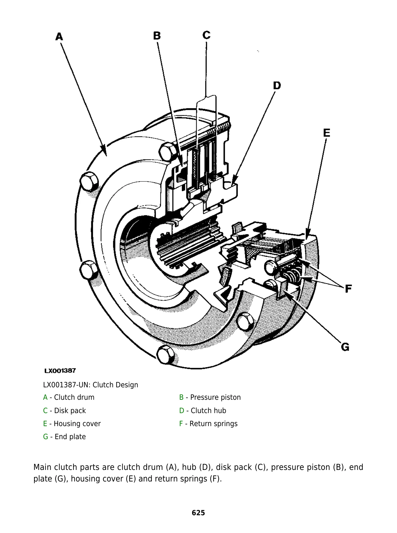
- Group 20A — Theory of Operation — Perma Clutch II
- Group 20B — Theory of Operation — Gear Transmission
- Group 20C — Theory of Operation — Creeper Transmission
- Group 20D — Theory of Operation — Range Transmission
- Section 255 — PowrQuad Transmission
- Group 05 — Operational Checks
- Group 10 — System Diagnosis
- Group 15 — Adjustments
- Group 20 — Theory of Operation — PowrQuad Transmission
IMAGES PREVIEW


- Section 256 — Drive Systems (Without Transmission)
- Group 05 — Operational Checks
- Group 10 — System Diagnosis
- Group 15 — System Tests
- Group 20A — Theory of Operation — Front-Wheel Drive Clutch
- Group 20B — Theory of Operation — Differential
- Group 20C — Theory of Operation — Final Drives
- Group 20D — Theory of Operation — Rear PTO Options
- Section 260 — Steering and Brakes
- Group 05 — Operational Checks
- Group 10 — System Diagnosis
- Group 15 — System Tests
- Group 20 — Theory of Operation (Complete System)
- Group 20A — Hydrostatic Steering
- Group 20B — Hydraulic Brakes
- Section 270 — Hydraulic System
- Group 05 — Operational Checks
- Group 10 — System Diagnosis
- Group 15 — System Tests
- Group 20 — Hydraulic System
- Group 20A — Charge Pump
- Group 20B — Hydraulic Pump
- Group 20C — Hydraulic System Valves
- Group 20D — Rockshaft and Lift Cylinders
- Group 20E — Selective Control Valves and Couplers
- Group 20F — Independent Control Valve
- Section 290 — Operator’s Station
- Group 05 — Operational Checks
- Group 10A — Air Conditioning — System Diagnosis
- Group 10B — Ventilation and Heater — System Diagnosis
- Group 10C — Operator’s Seat — System Diagnosis
- Group 20A — Air Conditioning System — Theory of Operation
- Group 20B — Ventilation and Heater — Theory of Operation
- Section 299 — Special Tools (Dealer-Fabricated)
- Group 05 — Special Tools (Dealer-Fabricated)
What This Manual Provides
This John Deere 6200, 6300, 6400, 6500 and L Series Operation and Tests Technical Manual is structured to help a technician identify routine failures quickly and accurately. Rather than describing how to rebuild components — that is the job of the Repair Manual TM4523 — this volume focuses on the diagnostic journey: operational checks, system tests, step-by-step hydraulic test charts, electrical voltage checks, and the theory of operation that explains how each system is supposed to behave.
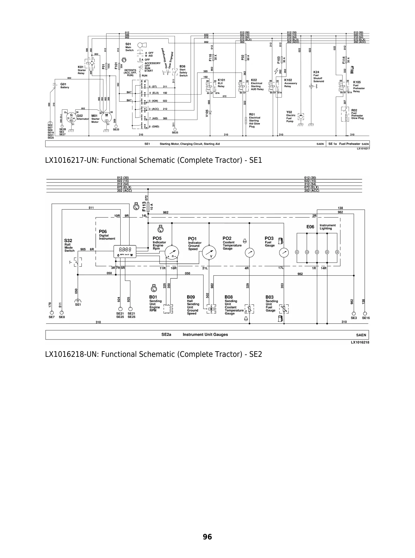
For the electrical system, the manual includes complete functional schematics, wiring and harness diagrams, diagnostic schematics, and sub-system diagnostics broken down by circuit. There are dedicated sections covering starting and charging, instrument unit and lighting, front wheel drive, differential lock, rear PTO, hazard warning and turn signals, work lights, power outlet sockets, radio and dome lights, blower and air conditioning, windshield wipers and washers, clutch cooling, beacon light, electronic rockshaft control and back-up alarm. Each sub-system includes both a functional and diagnostic schematic plus voltage checks.
The transmission coverage is particularly thorough. SyncroPlus and PowrQuad transmissions are each handled with operational checks, system diagnosis, system tests and theory of operation. The PowrQuad section includes the electronic reverser control (RCU) diagnostic trouble codes, a full list of service codes with descriptions, diagnostic addresses, calibration addresses and identification addresses. There is a shortened diagnostic procedure and a PowrQuad transmission test record sheet. The SyncroPlus section covers the Perma Clutch II, gear transmission, creeper transmission and range transmission, with power flow diagrams for each gear range.
Hydraulic system diagnosis follows a structured sequence: preliminary checks, heating the oil, connecting the JT07115 test kit, layout of test ports, system pressure tests, lube oil pressure checks, flow rate measurement, and checks for the filter relief valve, cooler relief valve, lube relief valve and pressure regulating valve. The rockshaft and lift cylinder section includes electronic hitch control (HCU) diagnostics with service codes, calibration procedures and diagnostic addresses. Selective control valves are covered in both 200 Series and 300 Series versions with neutral, extend, retract and float positions explained through oil flow diagrams.
Steering and brakes have their own system tests, including hydrostatic steering valve checks, shock valve testing and adjustment, brake system bleeding, brake piston travel measurement, stop light switch adjustment and rear brake checking. The operator’s station section covers air conditioning diagnosis, ventilation and heater diagnosis, operator’s seat diagnosis for the MSG95 seat, and the theory of operation for the refrigerant circuit and heating system.
The manual also includes specifications at the start of each group, lists of special or essential tools, and safety precautions that apply throughout. Dealer-fabricated tools are covered in Section 299, including the DFRW2 needle valve test hose assembly and DFRW85 reverse brake test plate.
Who This Manual Is For
This John Deere 6200, 6300, 6400, 6500 and L Series Operation and Tests Technical Manual is written for the experienced technician. It assumes familiarity with basic theory of operation, fundamentals of troubleshooting and general maintenance practices. The information is presented as an on-the-job guide containing the vital information needed for diagnosis, analysis, testing and repair of these tractor models.
Whether you are diagnosing an electrical fault on a 6400, testing hydraulic system pressure on a 6500L, calibrating the rockshaft control on a 6300, or working through PowrQuad transmission service codes on a 6200, this manual gives you the test procedures, specifications and theory needed to complete the job correctly. The step-by-step diagnostic charts and voltage check tables are designed to be followed in sequence, leading you to the cause of the fault without guesswork.
Because this is the Operation and Tests volume, it is the manual you reach for when something is not working right — not when something needs to be rebuilt. It tells you what pressures to expect, what voltages to look for, what codes mean, and how each system is supposed to operate. That makes it invaluable for troubleshooting and for verifying repairs after they are completed.
Why This Manual Matters
Working on modern agricultural tractors without the correct test procedures and specifications is a recipe for wasted time and misdiagnosed faults. The John Deere 6200, 6300, 6400, 6500 and L Series tractors use electronically controlled transmissions, hydraulically actuated hitch systems, load-sense hydraulics and complex electrical networks. Guessing at pressures, voltages or calibration values can lead to incorrect repairs, damaged components or unsafe operation.
This manual provides the actual specifications and test sequences used to diagnose these systems. It tells you the system engagement pressure should be 1200 ± 50 kPa (12 ± 0.5 bar; 170 ± 7 psi) at 2300 rpm. It tells you the lube oil pressure should be at least 75 kPa (0.75 bar; 11 psi) at 1000 rpm and 350 ± 100 kPa (3.5 ± 1 bar; 51 ± 15 psi) at 2300 rpm at 45°C. It gives you the opening pressures for the cooler relief valve, the closing pressures for the A/C high/low pressure switch, the resistance values for the load center relays, and the calibration index numbers for the lift cylinder and draft sensor on each tractor model.
Having these values on hand means you can test with confidence, compare your readings against the specification, and know whether a component is within tolerance or needs replacement. It also means you can calibrate the hitch control correctly after replacing a sensor or control unit — a step that is absolutely necessary for proper operation and that cannot be done without the calibration procedure documented here.
Instant PDF Delivery
This John Deere 6200, 6300, 6400, 6500 and L Series Operation and Tests Technical Manual TM4524 is delivered as a PDF download immediately after payment. There is no shipping, no waiting for a physical book, and no restrictions on where you can use it. The file can be viewed on any device — laptop, tablet, smartphone or desktop computer — and pages can be printed for use in the workshop.
The PDF format makes it easy to search for specific sections, jump to the diagnostic address or service code you need, and keep the manual open on a screen while you work on the tractor. You get the complete manual in one file, with all the electrical schematics, hydraulic circuit diagrams, test charts and specification tables intact.
Whether you are a professional technician, a farm owner maintaining your own equipment, or someone who needs the correct diagnostic information for these John Deere tractors, this manual provides the technical depth and practical guidance you need. It is the definitive operation and tests reference for the 6200, 6200L, 6300, 6300L, 6400, 6400L, 6500 and 6500L tractor models.
Reviews
There are no reviews yet.