★ TRUSTED BY 321,897+ PROFESSIONALS WORLDWIDE
🏢
Trusted Business
Verified & Licensed
🛡️
Virus Free Files
100% Safe Downloads
🔒
Secure Payment
SSL Protected
Instant Delivery
Available Immediately
Sale!

John Deere C Series II Motor Graders Operation & Test Manual TM1914

Original price was: $39.95.Current price is: $24.95.

Complete John Deere C Series II motor graders operation and test manual TM1914 covering 670C, 670CH, 672CH, 770C, 770CH and 772CH models with 6068 and 6081 engines. Full diagnostic procedures, theory of operation, tests and adjustments for engine, electrical, powertrain, hydraulic, HFWD and HVAC systems. 849 pages.

Instant PDF Download
Available immediately
💾
Save to Your Device
Download & keep forever
🛡️
Antivirus Scanned
100% virus-free
🌍
Trusted Worldwide
175,000+ customers

Description

John Deere C Series II Motor Graders Operation & Test Manual TM1914

This John Deere C Series II Motor Graders Operation and Test Manual (TM1914) is the technical reference for diagnosing, testing and understanding the complete machine on 670C, 670CH, 672CH, 770C, 770CH and 772CH motor graders. Written for the experienced technician, it organizes every major system into theory of operation, diagnostic information, adjustments and tests, so a complete machine operational checkout or a single fault isolation can be worked from the same volume.

File Details

  • Manual type: Operation and Test Technical Manual
  • Brand: John Deere
  • Models covered: 670C, 670CH, 672CH, 770C, 770CH, 772CH
  • Engines referenced: 6068 (6.8 L) and 6081 (8.1 L)
  • Serial number breakdowns: S.N. —589368 and S.N. 589369—
  • Language: English
  • Page count: 849
  • File format: PDF
  • Document number: TM1914

Chapters Covered

  • General Information — Safety — operator qualification, protective equipment, high-pressure fluid hazards, exhaust fumes, fire prevention, battery explosions, chemical handling, ROPS inspection and safe service procedures
  • Operational Checkout Procedure — complete machine operational checkout with engine-off checks, engine-running checks and stored diagnostic trouble code retrieval
  • Engine — theory of operation, diagnostic information, adjustments and tests for 6068 and 6081 engines, including surge tank operation, air intake and exhaust system operation, cold start theory, engine air heater theory, ether start aid, and diagnostic procedures B1 and B2
  • Electrical System — system information, system diagrams, sub-system diagnostics, references and tests, with complete wiring diagrams for every machine harness, diagnostic trouble code reference lists, stored code retrieval and detailed component checks
  • Hydrostatic Front Wheel Drive (HFWD) — theory of operation, diagnostic information, adjustments and checks, tests covering pump and displacement control, charge pump, charge filter, flushing valve, multi-function valve, engagement valve, front wheel motor and power flow
  • Power Train — theory of operation, diagnostic information, adjustments and tests for the DF180 powershift transmission, park brake and differential lock control valve, park brake operation and manual release, differential lock operation, and rear axle and tandem operation
  • Hydraulic System — theory of operation, diagnose malfunctions, adjustments and tests for the main hydraulic system, main pump, return filter, system relief valve, service brake, brake accumulator, steering, priority control valve, grader control valve and all valve sections
  • Heating and Air Conditioning — theory of operation, diagnostic information and tests for the R134a air conditioning system and heater system

The John Deere C Series II Motor Graders Operation and Test Manual goes well beyond a list of specifications. It gives the technician structured diagnostic procedures for every major system on the machine — from the engine controller and electrical harnesses through the DF180 powershift transmission, hydrostatic front wheel drive, main hydraulic system and HVAC. Each section begins with theory of operation, then builds into diagnostic information, adjustments and tests so the reader understands not just what to check but why a failure produces the symptom it does.

Diagnostic trouble codes are covered in depth. The manual lists HFWD codes F213 through F274, transmission codes F301 through F398, and engine codes F401 through F487, each with symptom, probable cause and repair path. Stored diagnostic trouble code retrieval is explained for the monitor display. The electrical section provides complete wiring diagrams for the roof harness (W2), map light harness (W3), A/C roof harness (W7), under seat heater harness (W8), engine harnesses (W9 and W10), platform harness (W11), transmission harness (W13), side console harnesses (W15, W16 and W17), front console harness (W18), A/C compressor harness (W20), ripper harness (W21), 24V radio harness (W31), and HFWD front and rear harnesses (W34 and W35).

IMAGES PREVIEW

John Deere C Series II Motor Graders Operation & Test Manual TM1914 — PDF page 1 preview
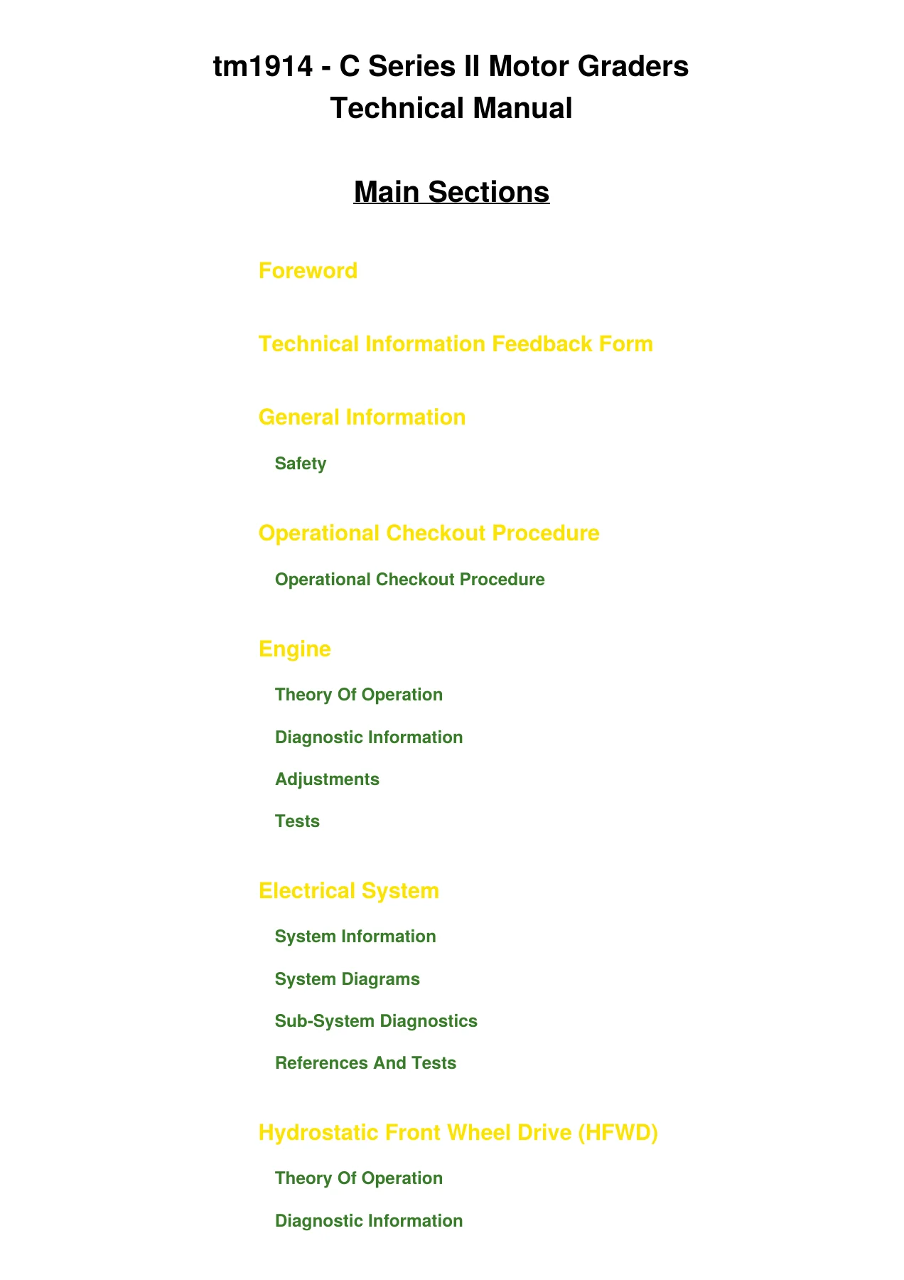
John Deere C Series II Motor Graders Operation & Test Manual TM1914 — PDF page 561 preview
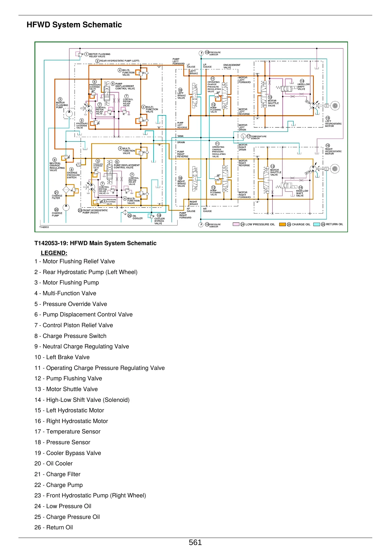
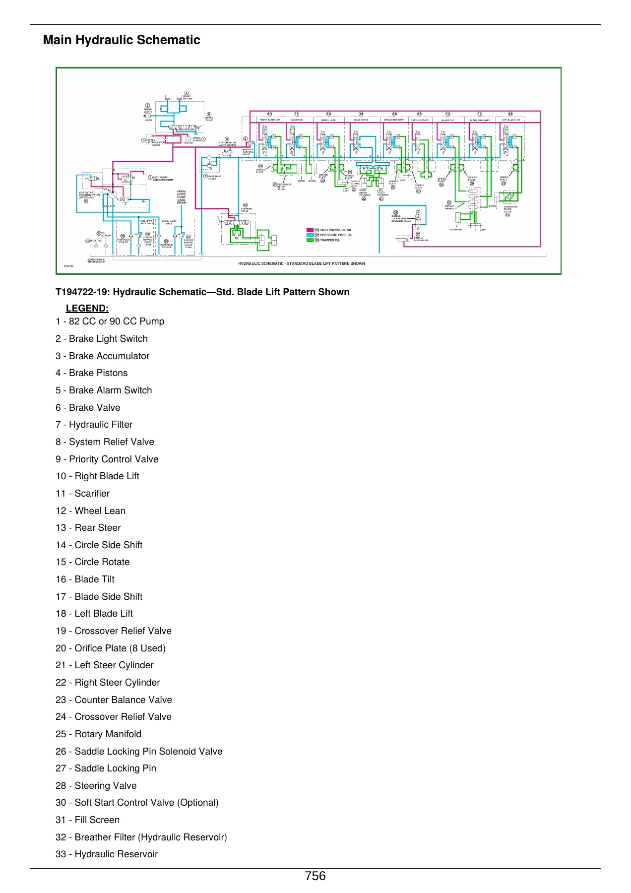
John Deere C Series II Motor Graders Operation & Test Manual TM1914 — PDF page 756 preview

The engine section covers both the 6068 (6.8 L) and 6081 (8.1 L) engines, with separate diagnostic procedures for machines built before and after serial number 589369. Topics include surge tank operation, air intake and exhaust system operation, cold start theory, ether start aid, engine air heater with and without ether start aid, and specific diagnostic procedures for hard starting and low power complaints. Engine tests include fuel line leakage, air intake system leakage, air filter restriction indicator switch, intake manifold pressure (turbocharger boost), injection pump rack position voltage, fuel supply pump leakage, fuel pressure and throttle potentiometer tests. The JT05801 clamp-on electronic tachometer installation, engine belt tensioner spring check, fan belt tensioner spring check, engine speed linkage adjustment for both 670C and later models, primary fuel filter drain valve procedures and fuel system bleeding for all model variants are also included.

The powertrain section explains the DF180 powershift transmission in detail — hydraulic system operation, control valve port identification, clutch pack operation, clutch and gear operation, park brake and differential lock control valve, park brake engaged and manual release operation, differential lock operation, and rear axle and tandem operation. Each transmission and axle test is included, from pump flow and system pressure through clutch pressure, park brake pressure and differential lock pressure tests. Transmission diagnostics include troubleshooting tips for F301 through F319 transmission gear solenoid codes and inching pedal codes, with guidance on limp-home mode behaviour when solenoid circuits fail. The transmission controller calibration procedure, transmission solenoid resistance test and transmission proportional solenoid valve test are all included, along with the transmission control and park brake lever test and the park/not neutral gear position switch module bench test.

The hydraulic section covers the main hydraulic system, main hydraulic pump, main hydraulic return filter, system relief valve, service brake operation, brake accumulator operation, steering system operation, priority control valve, grader control valve, control valve orifice operation, blade lift and scarifier and ripper valve operation, wheel lean and rear steer and circle side shift and blade tilt and blade side shift valve operation, counterbalance valve operation, circle rotate valve operation, locking pin circuit operation, ripper valve operation, and circle drive gearbox operation both with and without slip clutch.

Beyond diagnostics, the manual includes a full set of component checks for relays, diodes, the key switch, the aggressiveness switch, solenoid coils, transmission shaft speed pickups and the inching potentiometer, along with connector service procedures for METRI-PACK, DEUTSCH and WEATHER PACK connectors. Calibration procedures are provided for the tachometer, transmission controller (TCU), HFWD controller (HCU), inching pedal and articulation potentiometer. Fuse and relay specifications are broken out by serial number range, and the functional schematic and wiring diagram master legend is included to help trace any circuit.

Complete PDF Bookmark Tree

Complete Bookmarks

The complete bookmarks in the “John Deere C Series II Motor Graders Operation & Test Manual TM1914” are as follows:

Table of Contents
tm1914 – C Series II Motor Graders
Table of Contents
Foreword
Technical Information Feedback Form
Section 9000: General Information
Group 01: Safety
Recognize Safety Information
Follow Safety Instructions
Operate Only If Qualified
Wear Protective Equipment
Avoid Unauthorized Machine Modifications
Inspect Machine
Stay Clear of Moving Parts
Avoid High-Pressure Fluids
Beware of Exhaust Fumes
Prevent Fires
Prevent Battery Explosions
Handle Chemical Products Safely
Dispose of Waste Properly
Prepare for Emergencies
Use Steps and Handholds Correctly
Start Only From Operator's Seat
Use and Maintain Seat Belt
Prevent Unintended Machine Movement
Avoid Work Site Hazards
Keep Riders Off Machine
Avoid Backover Accidents
Avoid Machine Tip Over
Operating or Traveling On Public Roads
Inspect and Maintain ROPS
Add and Operate Attachments Safely
Park And Prepare For Service Safely
Service Cooling System Safely
Remove Paint Before Welding or Heating
Make Welding Repairs Safely
Drive Metal Pins Safely
Section 9005: Operational Checkout Procedure
Group 10: Operational Checkout Procedure
Complete Machine Operational Checkout
Section 9010: Engine
Group 05: Theory Of Operation
Supplement Support Manuals
Surge Tank Operation
Air Intake and Exhaust System Operation—6081 Engine
Cold Start Theory of Operation 670C, 770C, 770CH, 772CH (670CH, 672CH S.N. —589368)
Group 15: Diagnostic Information
Diagnose Engine Malfunctions (670CH, 672CH S.N. —589368 And 770C, 770CH, 772CH)
Diagnose Engine Malfunctions (670CH, 672CH S.N. 589369— )
Engine Cranks/Won’t Start or Starts Hard, Diagnostic Procedure (B1)—(670CH, 672CH, S.N. —589368 And 770C, 770CH, 772CH)
Engine Does Not Develop Full Power, Diagnostic Procedure (B2)— 770CH, 772CH
Group 20: Adjustments
JT05801 Clamp-On Electronic Tachometer Installation
Engine Belt Tensioner Spring Check
Fan Belt Tensioner Spring Check
Adjust Engine Speed Linkage—670C
Adjust Engine Speed Linkage—670CH, 672CH, 770C, 770CH, 772CH
Primary Fuel Filter, Drain Valve—670C, 670CH, 672CH (S.N. —589368)
Primary Fuel Filter, Drain Valve—670C, 670CH, 672CH (S.N. 589369—)
Primary Fuel Filter, Drain Valve—770C, 770CH, 772CH
Bleed The Fuel System—670C, 670CH, 672CH
Bleed The Fuel System—770C, 770CH, 772CH
Group 25: Tests
Fuel Line Leakage Test
Air Intake System Leakage Test
Air Filter Restriction Indicator Switch Test
Intake Manifold Pressure (Turbocharger Boost PSI) and Wastegate Test
Intake Manifold Pressure (Turbocharger Boost PSI) Test
Injection Pump Rack Position Voltage Test
Fuel Supply Pump Leakage Test—670C, 670CH, 672CH
Fuel Pressure Test—770C, 770CH, 772CH
Throttle Potentiometer Test—670CH, 672CH, 770C, 770CH, 772CH
Section 9015: Electrical System
Group 05: System Information
Electrical Diagram Information
Group 10: System Diagrams
Fuse and Relay Specifications (S.N. —589368)
Fuse and Relay Specifications (S.N. 589369— )
Functional Schematic, Wiring Diagram and Component Location Master Legend
System Functional Schematic Legend
System Functional Schematic
Roof Harness (W2) Wiring Diagram
Roof Harness (W2) Component Location
Map Light Harness (W3) Wiring Diagram
Map Light Harness (W3) Component Location
A/C Roof Harness (W7) Wiring Diagram
A/C Roof Harness (W7) Component Locationp. 1
Under Seat Heater Harness (W8) Wiring Diagramp. 1
Under Seat Heater Harness (W8) Component Locationp. 1
Engine Harness (W9) Wiring Diagramp. 1
Engine Harness (W9) Component Locationp. 1
Engine Harness (W10) Wiring Diagramp. 1
Engine Harness (W10) Component Locationp. 1
Platform Harness (W11) Wiring Diagramp. 1
Platform Harness (W11) Component Locationp. 1
Transmission Harness (W13) Wiring Diagramp. 1
Transmission Harness (W13) Component Locationp. 1
Side Console Harness (W15) Wiring Diagram (670C)p. 1
Side Console Harness (W15) Component Location (670C)p. 1
Side Console Harness (W16) Wiring Diagram (670CH, 770C, 770CH)p. 1
Side Console Harness (W16) Component Location (670CH, 770C, 770CH)p. 1
Side Console Harness (W17) Wiring Diagram (672CH and 772CH)p. 1
Side Console Harness (W17) Component Location (672CH and 772CH)p. 1
Side Console Harness—Detail Cp. 1
Front Console Harness (W18) Wiring Diagramp. 1
Front Console Harness (W18) Component Locationp. 1
A/C Compressor Harness (W20) Wiring Diagramp. 1
A/C Compressor Harness (W20) Component Locationp. 1
Ripper Harness (W21) Wiring Diagramp. 1
Ripper Harness (W21) Component Locationp. 1
24V Radio Harness (W31) Wiring Diagramp. 1
24V Radio Harness (W31) Component Locationp. 1
HFWD Front and Rear Harness (W34 and W35) Wiring Diagram (672CH, 772CH)p. 1
HFWD Front and Rear Harness (W34 and W35) Component Location (672CH, 772CH)p. 1
Group 15: Sub-System Diagnosticsp. 1
Starting and Park Brake Circuit Theory Of Operationp. 1
Soft Start Circuit Theory of Operation (If Equipped)
Transmission Controller Circuit Theory Of Operation
Engine Controller Circuit Theory Of Operation (670C, 770C)
Engine Controller Circuit Theory Of Operation (670CH, 672CH S.N. 589369— )
Display Monitor Circuit Theory Of Operation
Hydrostatic Front Wheel Drive (HFWD) Circuit Theory Of Operation
Group 20: References And Tests
Diagnostic Trouble Code Reference List
Stored Diagnostic Trouble Code Retrieval
Troubleshooting Tips F301—F308 Transmission Gear Solenoid Codes
Troubleshooting Tips F309—F319 Transmission Gear Solenoid Codes
Troubleshooting Tips F317—F319 Inching Pedal Codes
HFWD Controller Diagnostic Trouble Codes Diagnostics
Transmission Diagnostic Trouble Code Diagnostics
Engine Diagnostic Trouble Code Diagnostics 770C, 770CH, 772CH (672CH, 670CH S.N. —589368 )
Engine Diagnostic Trouble Codes (DTCs) On Level 11 ECU (672CH, 670CH S.N. 589369— )
Engine Air Heat Controller Module (A7) Diagnostic Trouble Codes (670C) (If Equipped)
Battery Specifications
Electrical Component Specifications
Electrical Component Checks
Monitor Set Up
Calibrate Tachometer
Calibrate Transmission Controller (TCU)
Calibrate HFWD Controller (HCU)
Inching Pedal Calibration
Articulation Potentiometer Adjustment
Replacing Radio Memory Batteries (If Equipped)
Transmission Solenoid Resistance Test
HFWD Temperature Switch (B37) Test
Transmission Control And Park Brake Lever Test
Park/Not Neutral Gear Position Switch Module (S6) And Forward/Reverse Switch Module (S7) Bench Test
Check Controller
Replace METRI-PACK METRI-PACK is a trademark of Packard Electric Inc. Connectors
Replace DEUTSCH DEUTSCH is a trademark of the Deutsch Co. Connectors
Replace DEUTSCH DEUTSCH is a trademark of Deutsch Co. Rectangular or Triangular Connectors
Install DEUTSCH DEUTSCH is a trademark of the Deutsch Co. Contact
Replace WEATHER PACK WEATHER PACK is a trademark of Packard Electric. Connector
Install WEATHER PACK WEATHER PACK is a trademark of Packard Electric. Contact
Halogen Lights
Section 9016: Hydrostatic Front Wheel Drive (HFWD)
Group 05: Theory Of Operation
Hydrostatic Front Wheel Drive (HFWD) System Operation
HFWD Pump And Displacement Control Operation
Forward Operation
HFWD Pump And Motor Flushing Pump
HFWD Charge Pump
HFWD Charge Filter Operation
Flushing Valve and Operating Charge Relief Valve
Multi-Function Valve
Engagement Valve Operation
Front Wheel Motor Operation
HFWD Power Flow
Group 15: Diagnostic Information
Diagnose Malfunctions Of Hydrostatic Front Wheel Drive
HFWD System Schematic
HFWD Component Location
Group 20: Adjustments And Checks
HFWD Start-Up Procedure
HFWD Pump Control Neutral Adjustment
Group 25: Tests
Digital Thermometer Installation
Digital Pressure And Temperature Analyzer Installation
Digital Hydraulic Tester
Avoid High-Pressure Fluids
HFWD Oil Warm-Up Procedure
HFWD Planetary Brake Leakage Test
HFWD Neutral Charge Regulating Valve Pressure Test
HFWD Operating Charge Regulating Valve Pressure Test
HFWD Charge Pressure Balance Test
HFWD Pump Leakage Test
HFWD Motor Leakage Test
Pressure Override & Multi-Function Relief Valve Test—Forward and Reverse Directions
HFWD Motor Flushing Pump Relief Valve Test
HFWD Charge Pump Flow Test
Cooler Bypass Valve Pressure Test
Hydraulic Oil Filter Inspection Procedure
Section 9020: Power Train
Group 05: Theory Of Operation
Transmission Operation
Transmission Hydraulic System Operation
Transmission Control Valve Port Identification
Clutch Pack Operation
Clutch and Gear Operation and Component Location
First Forward
Park Brake and Differential Lock Control Valve
Park Brake Operation
Park Brake—Engaged
Park Brake Manual Release Operation
Differential Lock Operation
Rear Axle and Tandem Operation
Group 15: Diagnostic Information
Diagnose DF180 Powershift Transmission And Hydraulic Related Malfunctions
Diagnose Park Brake Malfunctions
Diagnose Differential Malfunctions
Power Train Component Location
Group 20: Adjustments
Manual Park Brake Release Procedure
Group 25: Tests
Transmission and Axle Oil Warm-Up Procedure
Differential Lock Valve Pressure Test
Differential Lock Valve Leakage Test
Axle Cooler Relief Pressure Test
Transmission Pump Flow Test
Transmission System Pressure Test
Lube Pressure Test
Transmission Control Circuit Pressure Test
Transmission Cooler Inlet Pressure Test
Park Brake Pressure Test
Park Brake Warm-Up Circuit
Relief/Valve Fitting Pressure Test (Park Brake)
Transmission Oil Filter Inspection Procedure
Transmission Accumulator Charge Pressure Test (S.N. —589369)
Transmission Pump Suction Tube Leak Test
Transmission Proportional Solenoid Valve Test
Section 9025: Hydraulic System
Group 05: Theory Of Operation
Main Hydraulic System Operation
Main Hydraulic Pump Operation
Main Hydraulic Return Filter Operation
System Relief Valve Operation
Service Brake Operation
Service Brake Operation—Multiple Disk
Brake Accumulator Operation
Steering System Operation
Priority Control Valve Operation
Grader Control Valve Operation
Control Valve Orifice Operation
Blade Lift, Scarifier And Ripper Valve Operation—Neutral
Wheel Lean, Rear Steer, Circle Side Shift, Blade Tilt, And Blade Side Shift Valve Operation
Counterbalance Valve Operation
Circle Rotate Valve Operation
Locking Pin Circuit Operation
Ripper Valve Operation
Circle Drive Gearbox Operation—Without Slip Clutch
Circle Drive Gearbox Operation—With Slip Clutch
Group 15: Diagnose Malfunctions
Diagnose Malfunctions Of Hydraulic System
Diagnose Malfunctions Of Steering System
Diagnose Service Brakes
Hydraulic Circuit Symbols
Main Hydraulic Schematic
Main Hydraulic Component Location
Group 20: Adjustments
Control Lever Pattern Change
Group 25: Tests
JT05800 Digital Thermometer Installation
JT02156A Digital Pressure And Temperature Analyzer Installation
JT07148 Digital Hydraulic Tester
Hydraulic Oil Warm-Up Procedure
Vacuum Pump Installation
Main Pump Standby Pressure Test
Main Hydraulic Pump Leakage Test
Main Pump Flow Test
Pump Destroke Spike Test
Priority Control Valve Pressure Test
System Relief Valve Pressure Test
Counterbalance Valve Pressure Test
Counterbalance Valve Leakage Test
Crossover Relief Valve Pressure Test
Cooler Bypass Valve Pressure Test—Non-HFWD
Brake Valve Pressure Test
Brake Accumulator Precharge Test
Brake Light Switch Test
Hydraulic Component Neutral Leakage Test
Hydraulic Cylinder Drift Test
Hydraulic Cylinder Leakage Test
Crossover Relief Valve Leakage Test
Rotary Manifold Leakage Test
Steering System Leakage Test
Brake Accumulator Inlet Check Valves Leakage Test
Hydraulic Oil Filter Inspection Procedure
Cycle Time Test
Section 9031: Heating And Air Conditioning
Group 05: Theory Of Operation
Air Conditioning System Cycle Of Operation
Group 15: Diagnostic Information
Diagnose Air Conditioning System Malfunctions
Diagnose Heater System Malfunctions
Heating/Air Conditioning Component Location
Group 25: Tests
Air Conditioning Operational Checks
R134a Air Conditioning System Test
Operating Pressure Diagnostic Chart
A/C Freeze Control Switch Test
A/C Compressor Clutch Test
A/C Low Pressure Switch Test
A/C High Pressure Switch Test
A/C Expansion Valve Test
Expansion Valve Bench Test
Refrigerant Leak Test
Foreword
Technical Information Feedback Form
Recognize Safety Information
Follow Safety Instructions
Operate Only If Qualified
Wear Protective Equipment
Avoid Unauthorized Machine Modifications
Inspect Machine
Stay Clear of Moving Parts
Avoid High-Pressure Fluids
Beware of Exhaust Fumes
Prevent Fires
Prevent Battery Explosions
Handle Chemical Products Safely
Dispose of Waste Properly
Prepare for Emergenciesp. 2
Use Steps and Handholds Correctly
Start Only From Operator's Seat
Use and Maintain Seat Belt
Prevent Unintended Machine Movement
Avoid Work Site Hazards
Keep Riders Off Machine
Avoid Backover Accidents
Avoid Machine Tip Over
Operating or Traveling On Public Roads
Inspect and Maintain ROPS
Add and Operate Attachments Safely
Park And Prepare For Service Safely
Service Cooling System Safely
Remove Paint Before Welding or Heating
Make Welding Repairs Safely
Drive Metal Pins Safely
Complete Machine Operational Checkout
Supplement Support Manuals
Surge Tank Operation
Air Intake and Exhaust System Operation—6081 Enginep. 4
Base Machinep. 4
Optional Pre-Cleanerp. 4
Cold Start Theory of Operation 670C, 770C, 770CH, 772CH (670CH, 672CH S.N. —589368)
Engine Air Heater Theory of Operation
Ether Start Aid Theory of Operation
Engine Air Heater with Ether Start Aid Theory of Operation
Diagnose Engine Malfunctions (670CH, 672CH S.N. —589368 And 770C, 770CH, 772CH)
Diagnose Engine Malfunctions (670CH, 672CH S.N. 589369— )
Engine Cranks/Won’t Start or Starts Hard, Diagnostic Procedure (B1)—(670CH, 672CH, S.N. —589368 And 770C, 770CH, 772CH)
Engine Does Not Develop Full Power, Diagnostic Procedure (B2)— 770CH, 772CH
JT05801 Clamp-On Electronic Tachometer Installation
Engine Belt Tensioner Spring Check
Fan Belt Tensioner Spring Check
Adjust Engine Speed Linkage—670C
Pedal Slow Idle Adjustment
Injection Pump Yoke Adjustment
Pedal Fast Idle Adjustment
Adjust Engine Speed Linkage—670CH, 672CH, 770C, 770CH, 772CH
Engine Speed Linkage Adjustment
Fast Idle Potentiometer Resistance Adjustment
Primary Fuel Filter, Drain Valve—670C, 670CH, 672CH (S.N. —589368)
Primary Fuel Filter, Drain Valve—670C, 670CH, 672CH (S.N. 589369—)
Primary Fuel Filter, Drain Valve—770C, 770CH, 772CH
Bleed The Fuel System—670C, 670CH, 672CH
Bleed The Fuel System—770C, 770CH, 772CH
Fuel Line Leakage Test
Air Intake System Leakage Test
Air Filter Restriction Indicator Switch Test
Intake Manifold Pressure (Turbocharger Boost PSI) and Wastegate Test
Intake Manifold Pressure (Turbocharger Boost PSI) Test
Injection Pump Rack Position Voltage Test
Fuel Supply Pump Leakage Test—670C, 670CH, 672CH
Fuel Pressure Test—770C, 770CH, 772CH
Throttle Potentiometer Test—670CH, 672CH, 770C, 770CH, 772CH
Electrical Diagram Information
System Functional Schematic Diagram
Wiring Diagram—If Provided
Component Location Diagram
Connector End View Diagram—If Provided
Electrical Schematic Symbols
Electrical Diagram Information
System Functional Schematic Diagram
Wiring Diagram—If Provided
Component Location Diagram
Connector End View Diagram—If Provided
Electrical Schematic Symbols
Electrical Diagram Information
System Functional Schematic Diagram
Wiring Diagram—If Provided
Component Location Diagram
Connector End View Diagram—If Provided
Electrical Schematic Symbols
Fuse and Relay Specifications (S.N. —589368)
Fuse and Relay Specifications (S.N. 589369— )
Functional Schematic, Wiring Diagram and Component Location Master Legend
System Functional Schematic Legend
System Functional Schematic
Roof Harness (W2) Wiring Diagram
Roof Harness (W2) Component Location
Map Light Harness (W3) Wiring Diagram
Map Light Harness (W3) Component Location
A/C Roof Harness (W7) Wiring Diagram
A/C Roof Harness (W7) Component Location
Under Seat Heater Harness (W8) Wiring Diagram
Under Seat Heater Harness (W8) Component Location
Engine Harness (W9) Wiring Diagramp. 6
Engine Harness (W9) Component Location
Engine Harness (W10) Wiring Diagram
Engine Harness (W10) Component Location
Platform Harness (W11) Wiring Diagram
Platform Harness (W11) Component Location
Transmission Harness (W13) Wiring Diagram
Transmission Harness (W13) Component Location
Side Console Harness (W15) Wiring Diagram (670C)
Side Console Harness (W15) Component Location (670C)
Side Console Harness (W16) Wiring Diagram (670CH, 770C, 770CH)
Side Console Harness (W16) Component Location (670CH, 770C, 770CH)
Side Console Harness (W17) Wiring Diagram (672CH and 772CH)
Side Console Harness (W17) Component Location (672CH and 772CH)
Side Console Harness—Detail C
Front Console Harness (W18) Wiring Diagram
Front Console Harness (W18) Component Location
A/C Compressor Harness (W20) Wiring Diagram
A/C Compressor Harness (W20) Component Location
Ripper Harness (W21) Wiring Diagram
Ripper Harness (W21) Component Location
24V Radio Harness (W31) Wiring Diagram
24V Radio Harness (W31) Component Location
HFWD Front and Rear Harness (W34 and W35) Wiring Diagram (672CH, 772CH)
HFWD Front and Rear Harness (W34 and W35) Component Location (672CH, 772CH)
Starting and Park Brake Circuit Theory Of Operation
Starting Machine With Transmission Control and Park Brake Lever in PARK (P) Position
Machine Operation After Machine Has Started
Starting and Park Brake Circuit Theory Of Operation
Starting Machine With Transmission Control and Park Brake Lever in PARK (P) Position
Machine Operation After Machine Has Started
Soft Start Circuit Theory of Operation (If Equipped)
670C Soft Start Option
670CH, 672CH, 770C, 770CH, 772CH Soft Start Theory Option
Transmission Controller Circuit Theory Of Operation
Diagnostic Trouble Codes
Clutch Protection
Speed Matching
Down Shift Inhibit
Shuttle Shifting
X27 Transmission Calibration Connector Run and Calibrate Modes
Engine Controller Circuit Theory Of Operation (670C, 770C)
Engine Controller Circuit Theory Of Operation (670CH, 672CH S.N. 589369— )
Display Monitor Circuit Theory Of Operation
Hydrostatic Front Wheel Drive (HFWD) Circuit Theory Of Operationp. 7
Power Management Function
Diagnostic Trouble Codes
HFWD Controller Calibration
Diagnostic Trouble Code Reference List
HFWD Diagnostic Trouble Codes
Transmission Diagnostic Trouble Codes
Engine Diagnostic Trouble Codes 770C, 770CH, 772CH (S.N. —589368 672CH, 670CH)
Engine Diagnostic Trouble Codes (670CH, 672CH S.N. 589369— )
Diagnostic Trouble Code Reference List
HFWD Diagnostic Trouble Codes
Transmission Diagnostic Trouble Codes
Engine Diagnostic Trouble Codes 770C, 770CH, 772CH (S.N. —589368 672CH, 670CH)
Engine Diagnostic Trouble Codes (670CH, 672CH S.N. 589369— )
Stored Diagnostic Trouble Code Retrieval
Troubleshooting Tips F301—F308 Transmission Gear Solenoid Codes
F301—F308 Transmission Gear Solenoid Codes
Troubleshooting Tips F309—F319 Transmission Gear Solenoid Codes
Troubleshooting Tips F317—F319 Inching Pedal Codes
HFWD Controller Diagnostic Trouble Codes Diagnostics
Transmission Diagnostic Trouble Code Diagnostics
Engine Diagnostic Trouble Code Diagnostics 770C, 770CH, 772CH (672CH, 670CH S.N. —589368 )
Engine Diagnostic Trouble Codes (DTCs) On Level 11 ECU (672CH, 670CH S.N. 589369— )
Engine Air Heat Controller Module (A7) Diagnostic Trouble Codes (670C) (If Equipped)
Battery Specifications
Electrical Component Specifications
Monitor Gauge Specifications
Electrical Component Specifications
Electrical Component Checks
Monitor Set Up
Calibrate Tachometer
Calibrate Transmission Controller (TCU)
Calibrate HFWD Controller (HCU)
Inching Pedal Calibration
Articulation Potentiometer Adjustment
Replacing Radio Memory Batteries (If Equipped)
Transmission Solenoid Resistance Test
HFWD Temperature Switch (B37) Testp. 10
Transmission Control And Park Brake Lever Test
Park/Not Neutral Gear Position Switch Module (S6) And Forward/Reverse Switch Module (S7) Bench Test
Check Controller
Replace METRI-PACK ™ Connectors
Controller Connectors
Inching Switch Connectors
Replace DEUTSCH ™ Connectors
Replace DEUTSCH ™ Rectangular or Triangular Connectors
Install DEUTSCH ™ Contact
Replace WEATHER PACK ™ Connector
Install WEATHER PACK ™ Contact
Halogen Lights
Hydrostatic Front Wheel Drive (HFWD) System Operation
HFWD Pump And Displacement Control Operation
Forward Operation
HFWD Pump And Motor Flushing Pump
HFWD Charge Pump
HFWD Charge Filter Operation
Flushing Valve and Operating Charge Relief Valve
Multi-Function Valve
Engagement Valve Operation
Front Wheel Motor Operation
Neutral Operation (600 Series)
Neutral Operation (700 Series)
Forward or Reverse (Slow Speed—600 & 700 Series)
Forward or Reverse (High Speed—700 Series Only)
HFWD Power Flow
Diagnose Malfunctions Of Hydrostatic Front Wheel Drive
HFWD System Schematic
HFWD Component Location
HFWD Start-Up Procedure
HFWD Pump Control Neutral Adjustment
Digital Thermometer Installation
Digital Pressure And Temperature Analyzer Installation
Digital Hydraulic Tester
Avoid High-Pressure Fluids
HFWD Oil Warm-Up Procedure
HFWD Planetary Brake Leakage Test
HFWD Neutral Charge Regulating Valve Pressure Test
Neutral Charge Regulating Valve Pressure Test—Isolated (Valve Only)
HFWD Operating Charge Regulating Valve Pressure Test
HFWD Charge Pressure Balance Test
HFWD Pump Leakage Test
HFWD Motor Leakage Test
Pressure Override & Multi-Function Relief Valve Test—Forward and Reverse Directions
HFWD Motor Flushing Pump Relief Valve Test
HFWD Charge Pump Flow Test
Cooler Bypass Valve Pressure Test
Hydraulic Oil Filter Inspection Procedure
Transmission Operation
Transmission Hydraulic System Operation
Transmission Control Valve Port Identification
Clutch Pack Operation
Clutch and Gear Operation and Component Locationp. 12
First Forward
Park Brake and Differential Lock Control Valve
Park Brake Operation
Park Brake—Engaged
Park Brake Manual Release Operation
Differential Lock Operation
Rear Axle and Tandem Operation
Diagnose DF180 Powershift Transmission And Hydraulic Related Malfunctions
Diagnose Park Brake Malfunctions
Diagnose Differential Malfunctions
Power Train Component Location
Manual Park Brake Release Procedure
Transmission and Axle Oil Warm-Up Procedure
Differential Lock Valve Pressure Test
Differential Lock Valve Leakage Test
Axle Cooler Relief Pressure Test
Transmission Pump Flow Test
Transmission System Pressure Test
Lube Pressure Test
Transmission Control Circuit Pressure Test
Transmission Cooler Inlet Pressure Test
Park Brake Pressure Test
Park Brake Warm-Up Circuit
Relief/Valve Fitting Pressure Test (Park Brake)
Transmission Oil Filter Inspection Procedure
Transmission Accumulator Charge Pressure Test (S.N. —589369)
Transmission Pump Suction Tube Leak Test
Transmission Proportional Solenoid Valve Test
Main Hydraulic System Operation
Main Hydraulic Pump Operation
Main Hydraulic Return Filter Operation
Indicator Switch Operation
Bypass Valve Operation
System Relief Valve Operation
Service Brake Operation
Service Brake Operation—Multiple Disk
Brake Accumulator Operation
Steering System Operationp. 14
Neutral Positionp. 14
Right Hand Turn
Manual Steering
Priority Control Valve Operation
Grader Control Valve Operation
Control Valve Orifice Operation
Blade Lift, Scarifier And Ripper Valve Operation—Neutral
Wheel Lean, Rear Steer, Circle Side Shift, Blade Tilt, And Blade Side Shift Valve Operation
Counterbalance Valve Operation
Circle Rotate Valve Operation
Locking Pin Circuit Operation
Ripper Valve Operation
Circle Drive Gearbox Operation—Without Slip Clutch
Circle Drive Gearbox Operation—With Slip Clutch
Diagnose Malfunctions Of Hydraulic System
Diagnose Malfunctions Of Steering System
Diagnose Service Brakes
Hydraulic Circuit Symbols
Main Hydraulic Schematicp. 18
Main Hydraulic Component Location
Control Lever Pattern Change
Control Lever Pattern Changep. 19
JT05800 Digital Thermometer Installation
JT02156A Digital Pressure And Temperature Analyzer Installation
JT07148 Digital Hydraulic Tester
Hydraulic Oil Warm-Up Procedure
Vacuum Pump Installation
Main Pump Standby Pressure Test
Main Hydraulic Pump Leakage Test
Main Pump Flow Test
Pump Destroke Spike Test
Priority Control Valve Pressure Testp. 21
System Relief Valve Pressure Test
Counterbalance Valve Pressure Test
Counterbalance Valve Leakage Test
Crossover Relief Valve Pressure Test
Cooler Bypass Valve Pressure Test—Non-HFWD
Brake Valve Pressure Test
Brake Accumulator Precharge Test
Brake Light Switch Testp. 23
Hydraulic Component Neutral Leakage Test
Grader Control Valve
Steering Valve
Ripper Solenoid Valve
Brake Valve Leakage Test
Saddle Locking Pin Leakage Test
Hydraulic Cylinder Drift Test
Hydraulic Cylinder Leakage Test
Crossover Relief Valve Leakage Test
Rotary Manifold Leakage Test
Steering System Leakage Test
Brake Accumulator Inlet Check Valves Leakage Test
Hydraulic Oil Filter Inspection Procedure
Cycle Time Test
Air Conditioning System Cycle Of Operation
Diagnose Air Conditioning System Malfunctionsp. 26
Diagnose Air Conditioning System Malfunctions
Diagnose Heater System Malfunctions
Heating/Air Conditioning Component Location
Air Conditioning Operational Checks
All Lines and Hoses
Air Conditioner Compressor Check
Condenser Check
Heater/Evaporator Core Check
Freeze Control Switch Capillary Tube Check
Cab Door and Window Seals Check
Filter Check
Air Conditioning Operational Checksp. 27
All Lines and Hosesp. 27
Air Conditioner Compressor Checkp. 27
Condenser Checkp. 27
Heater/Evaporator Core Check
Freeze Control Switch Capillary Tube Check
Cab Door and Window Seals Check
Filter Check
R134a Air Conditioning System Test
Operating Pressure Diagnostic Chart
A/C Freeze Control Switch Test
A/C Compressor Clutch Test
A/C Low Pressure Switch Test
A/C High Pressure Switch Test
A/C Expansion Valve Test
Expansion Valve Bench Test
Refrigerant Leak Test

The HFWD section covers pump and displacement control operation, forward operation, pump and motor flushing pump, charge pump, charge filter operation, flushing valve and operating charge relief valve, multi-function valve, engagement valve operation, front wheel motor operation and HFWD power flow, followed by the full set of HFWD tests — start-up procedure, pump control neutral adjustment, planetary brake leakage, neutral and operating charge regulating valve pressure, charge pressure balance, pump leakage, motor leakage, pressure override and multi-function relief valve, motor flushing pump relief valve, charge pump flow and cooler bypass valve pressure.

Component location diagrams are provided for the roof harness, map light harness, A/C roof harness, under seat heater harness, engine harnesses, platform harness, transmission harness, side console harnesses, front console harness, A/C compressor harness, ripper harness, 24V radio harness, and HFWD front and rear harnesses, with separate diagrams for pre-589369 and post-589369 machines where the harness or routing changed.

What This Manual Enables

With the John Deere C Series II Motor Graders Operation and Test Manual on hand, a technician can perform a complete machine operational checkout from the operator’s seat, isolate faults across the engine, electrical, powertrain, hydraulic and HVAC systems, retrieve and interpret diagnostic trouble codes, run the full range of pressure, flow, leakage and cycle-time tests, calibrate the tachometer, transmission controller, HFWD controller and inching pedal, and reference the exact wiring diagram for any harness on the machine. The procedures are written so a repair can be planned and verified rather than guessed at — which matters on a grader where a misdiagnosed hydraulic or transmission fault can mean days of downtime.

Delivered as an instant PDF download, the manual is printable and works on any device. No shipping, no waiting.
Reviews

There are no reviews yet.

Be the first to review “John Deere C Series II Motor Graders Operation & Test Manual TM1914”

What Our Customers Say

★★★★★ Live reviews from customers
Loading customer reviews...
0
    0
    Your Cart
    Your cart is emptyReturn to Shop
    🛒
    Recently Purchased
    🕒 verified order