
Kaeser BSD 40 50 60 SIGMA CONTROL 2 Screw Compressor Service Manual
Original price was: $34.95.$19.95Current price is: $19.95.
Complete Kaeser service manual for BSD 40, BSD 50 and BSD 60 rotary screw compressors with SIGMA CONTROL 2 controller – technical data, safety, installation, operation, fault recognition, maintenance and full annex with P+I diagrams, dimensional and electrical drawings. Document 9_5708 23 USE. Instant PDF download.
Description
Kaeser BSD 40 / BSD 50 / BSD 60 Screw Compressor Service Manual with SIGMA CONTROL 2
This is the full service manual issued by Kaeser for the BSD 40, BSD 50 and BSD 60 rotary screw compressor packages fitted with the SIGMA CONTROL 2 operating panel. It covers the machine from first arrival through years of scheduled maintenance, and it is the same document number 9_5708 23 USE referenced on the machine documentation set. Everything a technician, plant engineer or maintenance planner needs to keep these units running to specification is contained in one file.
File Details
- Manual type: Service / operating manual (Original instructions)
- Brand: Kaeser Kompressoren
- Model series: BSD 40, BSD 50, BSD 60
- Controller: SIGMA CONTROL 2
- Document number: 9_5708 23 USE
- Internal reference: /KKW/SBSD 2.03 en 01, SBA-SCHRAUBEN-SC /KKW/SSC 2.02 01
- Language: English
- Page count: 144 pages
- File format: PDF
Chapters Covered
- 1. Regarding this Document – Using this document, Further documents, Copyright, Symbols and labels, Warnings, Potential damage warnings
- 2. Technical Data – Nameplate, Options, Weight, Temperature, Ambient conditions, Ventilation, Pressure, Delivery, Cooling Oil Recommendation, KAESER Lubricants, Cooling oil charge, Motors and power, Compressor motor, Fan motor, Noise emission, Power Supply, Power supply specifications, Water-cooling design data, Cooling water quality, Heat recovery (external and internal)
- 3. Safety and Responsibility – Basic instructions, Specified use, Improper use, User’s responsibilities, Qualified personnel, Dangers, Safe machine operation, Organizational measures, Danger areas, Safety devices, Safety signs, Emergency situations, Fire fighting, Treating cooling oil injuries, Warranty, Environmental protection
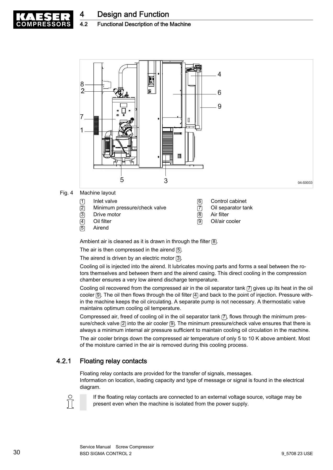
- 4. Design and Function – Enclosure, Functional description of the machine, Floating relay contacts, Options (machine mountings, water-cooling, cooling air filter mat, heat recovery), Operating modes, Control modes (DUAL, QUADRO, VARIO, MODULATING), Safety devices, Operating panel SIGMA CONTROL 2
- 5. Installation and Operating Conditions – Ensuring safety, Installation conditions, Determining location and clearances, Machine room ventilation, Exhaust duct design, Operating in a compressed air network
- 6. Installation – Ensuring safety, Reporting transport damage, Connecting to the compressed air network, Connecting the power supply, Options (anchoring, cooling water connection, heat recovery connection)
- 7. Initial Start-up – Safety, Pre-commissioning instructions, Checking installation and operating conditions, Setting overload protection relays, Filling cooling oil into the airend, Activating/deactivating MODULATING control, First start, Setting set point pressure, Setting display language
- 8. Operation – Switching on and off, Emergency shutdown and restart, Remote control centre operation, Clock control, Interpreting operation messages, Acknowledging alarm and warning messages
- 9. Fault Recognition and Rectification – Basic instructions, Other faults
- 10. Maintenance – Ensuring safety, Following the maintenance plan, Logging maintenance work, Resetting maintenance interval counters, Regular maintenance tasks, Cooling oil changing interval, Regular service tasks, Control cabinet filter mat, Cooler maintenance, Water-cooling maintenance, Cooling air filter mat, Heat recovery maintenance, Air filter change, Motor maintenance, Coupling check, Safety relief valve test, Overheating safety shutdown check, Cooling oil level, Venting the machine, Replenishing cooling oil, Changing the cooling oil, Changing the oil filter, Changing the oil separator cartridge, Documenting maintenance
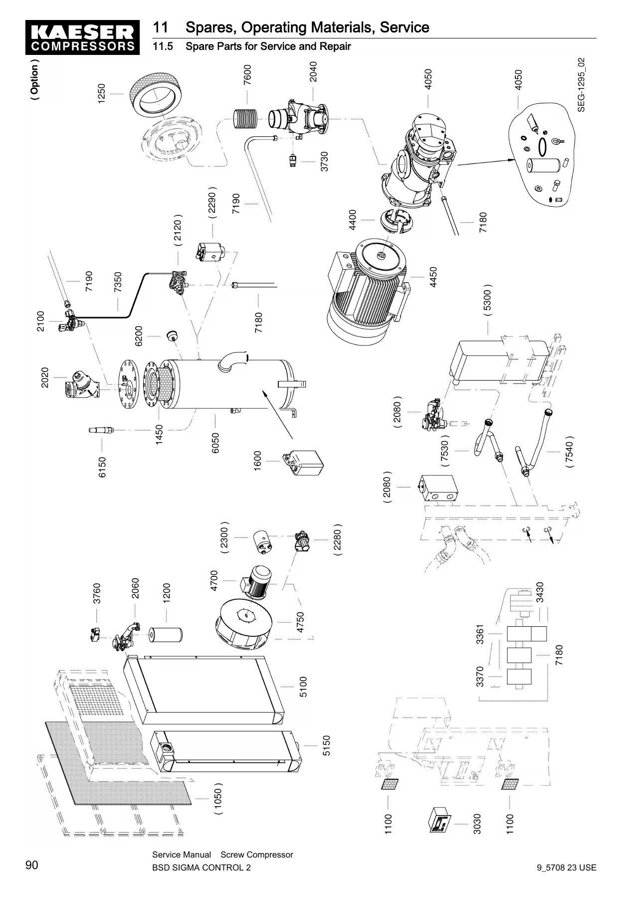
- 11. Spares, Operating Materials, Service – Nameplate, Ordering consumables, KAESER AIR SERVICE, Service addresses, Spare parts for service and repair
- 12. Decommissioning, Storage and Transport – Putting out of operation, Packing, Storage, Transport (safety, forklift, crane), Disposal
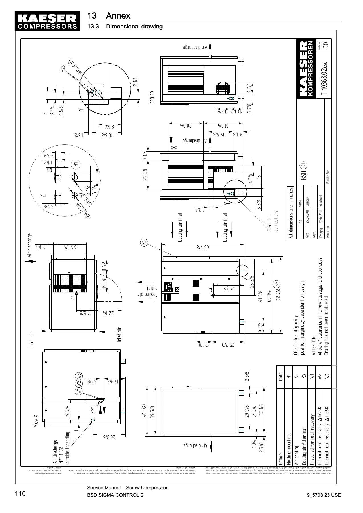
- 13. Annex – Pipeline and instrument flow diagrams (standard and MODULATING control), Dimensional drawings, Electrical diagrams
Together these chapters build a complete service picture: how the air end, drive motor, oil circuit, cooler and controls interact; the pressures, temperatures, oil quantities, ventilation figures and electrical supply data specific to each of the three BSD sizes; and the step-by-step procedures that take a unit from delivery through to full overhaul. The safety, danger area and emergency chapters give operators the background they need, while the fault and maintenance chapters are written for the person actually holding the tools.
What This Manual Lets You Do
Because every procedure is written around the BSD 40, BSD 50 and BSD 60 platforms and the SIGMA CONTROL 2 panel, you can work confidently on:
- Correctly commissioning a new or long-stored BSD compressor, including filling the airend with cooling oil, setting the overload protection relays and configuring the display language
- Choosing and confirming the right power supply hook-up for 208 V, 230 V, 380 V, 460 V or 575 V three-phase operation
- Setting, testing and resetting the safety relief valve, minimum pressure / check valve and overheating safety shutdown
- Reading P+I diagrams for both the standard machine and the option C1 MODULATING control variant
- Diagnosing common operational faults such as no compressed air delivery, excessive LOAD/IDLE cycling, oil consumption and oil leakage
- Draining, flushing and refilling the cooling oil circuit across the oil separator tank, oil cooler, airend, oil tank and heat recovery system
- Replacing the oil filter, oil separator cartridge, air filter element and control cabinet / cooling air filter mats
- Servicing the heat recovery options W1, W2 and W3, including the internal plate heat exchanger
- Checking motor bearings, greasing with EXXON UNIREX N3, inspecting the coupling and reading coupling wear symptoms
- Planning yearly and multi-year service tasks: valve checks, motor bearing checks, hose line replacement, cooler leak inspection
- Wiring the machine from the supplied electrical diagram, including the transformer tap settings for different supply voltages
- Decommissioning, packing, storing and transporting the unit safely, and disposing of cooling oil and contaminated parts correctly
Working without the specified values is where screw compressors get expensive: the wrong oil interval or the wrong overload relay setting can destroy a motor or clog an airend in weeks. Having the manufacturer’s own figures for temperatures, pressures, oil capacities, torques and inspection intervals in front of you is what separates a quick correct job from a repeat call-out.
Why This Matters
The BSD range runs in industrial compressed air stations where downtime is measured in production hours. This manual gives you Kaeser’s own guidance on flow rate, cooling water quality, heat recovery capacity, pressure limits and safety device test procedure, so the machine is kept inside its design envelope instead of being guessed at. The maintenance plan is set out by interval in operating hours and by calendar, and each task cross-refers to the chapter that explains it in full.
IMAGES PREVIEW
Instant PDF Delivery
The manual is supplied as a PDF that downloads immediately after payment. There is no shipping, no waiting for a parcel and no restriction on which device you read it on – open it on a laptop in the plant, a tablet in the compressor room or a phone while you are standing at the machine. Print only the pages you need for the task in front of you, or print the whole file and keep a hard copy in the service binder.
Reviews
There are no reviews yet.