
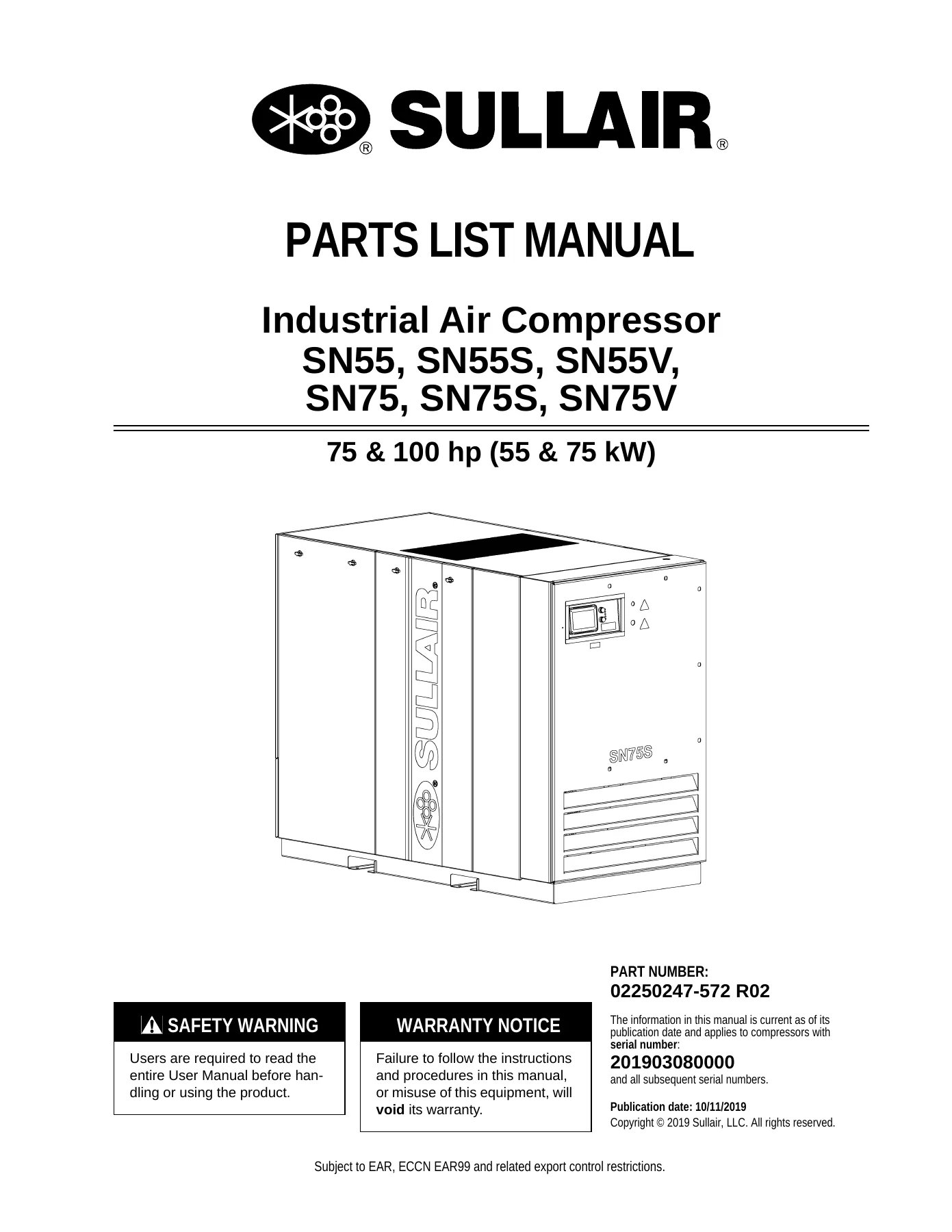
Sullair SN55 SN55S SN55V SN75 SN75S SN75V Parts List Manual 02250247-572 R02 – 2019
Original price was: $34.95.$21.95Current price is: $21.95.
154-page illustrated Sullair parts list manual for SN55, SN55S, SN55V, SN75, SN75S, and SN75V 75/100 hp rotary screw compressors. Exploded views and itemized part numbers for every major assembly, published under 02250247-572 R02 and covering serial number 201903080000 and up.
Description
Sullair SN55, SN55S, SN55V, SN75, SN75S, SN75V Parts List Manual — 02250247-572 R02
This Sullair SN55, SN55S, SN55V, SN75, SN75S, and SN75V Parts List Manual is the illustrated parts catalog for the 75 and 100 hp (55 and 75 kW) rotary screw compressor line. Published under part number 02250247-572 R02 with a publication date of 10/11/2019, it applies to units from serial number 201903080000 and all subsequent serial numbers. The document runs 154 pages and is built around exploded-view drawings paired with itemized parts tables, so every numbered callout on a diagram maps directly to a part number, description, and quantity.
File Details
- Manual type: Illustrated Parts List Manual
- Brand: Sullair
- Models covered: SN55, SN55S, SN55V, SN75, SN75S, SN75V
- Capacity range: 75 & 100 hp (55 & 75 kW)
- Document number: 02250247-572 R02
- Publication date: 10/11/2019
- Serial number applicability: 201903080000 and all subsequent serial numbers
- Language: English
- Page count: 154
- File format: PDF
Chapters Covered
- 1.1 Procedure for ordering parts
- 1.2 Recommended spare parts list
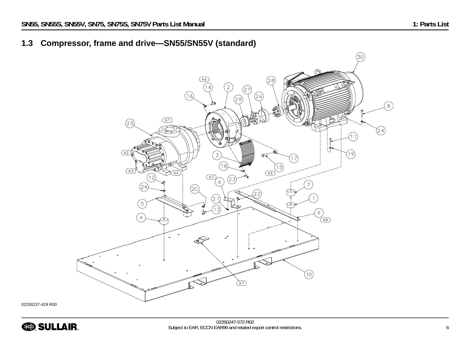
- 1.3 Compressor, frame and drive—SN55/SN55V (standard)
- 1.4 Compressor, frame and drive—SN55/SN55V (HA) and SN75 (standard)
- 1.5 Compressor, frame and drive—SN55S (standard)
- 1.6 Compressor, frame and drive—SN55S (HA) and SN75S/SN75V (standard)
- 1.7 Air inlet system—SN55, SN55V, SN75
- 1.8 Air inlet system—SN55S/SN75S/SN75V
- 1.9 Air piping, air-cooled
- 1.10 Air piping, water-cooled
- 1.11 Fluid piping, air-cooled—SN55/SN55V/SN75
- 1.12 Fluid piping, air-cooled—SN55S/SN75S/SN75V
- 1.13 Fluid piping, water-cooled—SN55/SN55V/SN75 (standard)
- 1.14 Fluid piping, water-cooled—SN55/SN55V/SN75 (regulating valve)
- 1.15 Fluid piping, water-cooled—SN55S/SN75S/SN75V (standard)
- 1.16 Fluid piping, water-cooled—SN55S/SN75S/SN75V (regulating valve)
- 1.17 Cooling system, air-cooled—SN55/SN55S/SN55V (460V)
- 1.18 Cooling system, air-cooled—SN75/SN75S/SN75V (460V)
- 1.19 Cooling system, water-cooled
- 1.20 Aftercooler, water-cooled
- 1.21 Water piping, water-cooled (standard)
- 1.22 Water piping, water-cooled (water solenoid valve & water regulating valve)
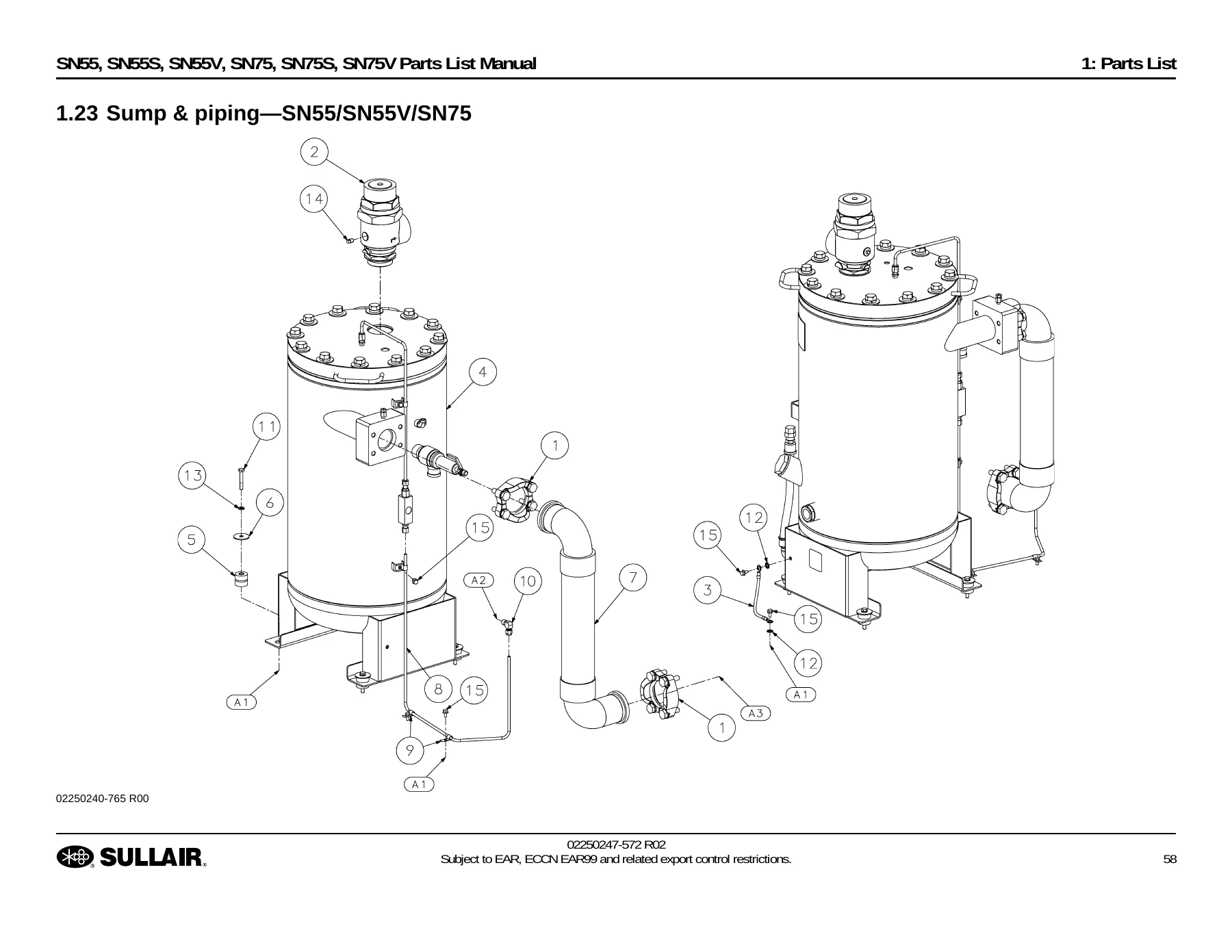
- 1.23 Sump & piping—SN55/SN55V/SN75
- 1.24 Sump & piping—SN55S/SN75S/SN75V
- 1.25 Sump tank assembly
- 1.26 Moisture drain (standard)
- 1.27 Moisture drain (zero loss)
- 1.28 Pneumatic control—SN55/SN75 (nylon)
- 1.29 Pneumatic control—SN55/SN75 (stainless steel)
- 1.30 Pneumatic control—SN55V (nylon)
- 1.31 Pneumatic control—SN55V (stainless steel)
- 1.32 Pneumatic control—SN55S/SN75S (nylon)
- 1.33 Pneumatic control—SN55S/SN75S (stainless steel)
- 1.34 Pneumatic control—SN75V (nylon)
- 1.35 Pneumatic control—SN75V (stainless steel)
- 1.36 Electrical control, air cooled
- 1.37 Electrical control, water cooled
- 1.38 Starter box (wye-delta)
- 1.39 Starter box (VSD)
- 1.40 Starter box display
- 1.41 Starter mounting (wye-delta)
- 1.42 Starter mounting (VSD)
- 1.43 Control starter (wye-delta, 460V & 575V)
- 1.44 Control starter—SN55V (460V)
- 1.45 Control starter—SN75V (460V)
- 1.46 Enclosure, air-cooled
- 1.47 Enclosure, water-cooled
- 1.48 Decal locations, air-cooled
- 1.49 Decal locations, water-cooled
Across those 49 sections, this Sullair SN55 and SN75 parts list manual breaks the compressor down into every serviceable assembly. The compressor, frame, and drive chapters cover the airend, motor adapter, coupling guard, coupling element and hubs, vibration isolators, mounting hardware, and frame assembly. The air inlet chapters show the two-stage air filter, inlet valve, restriction indicator, flex hose, and support brackets. Air piping chapters cover both air-cooled and water-cooled configurations, including the discharge pipe assembly, package outlet, and separator connections. Fluid piping chapters detail the thermal valve, fluid filter, SAE and ORFS fittings, hoses, and O-rings for each configuration — air-cooled and water-cooled, standard and regulating-valve layouts, across SN55/SN55V/SN75 and SN55S/SN75S/SN75V groups.
Recommended Spare Parts and Maintenance Kits
Section 1.2 is especially useful for planning. It lists the recommended spare parts — compressor fluid filters, air filter assemblies, separator replacement elements, and service kits — alongside a set of maintenance kits organized by interval. The 2000-hour, 8000-hour, and yearly maintenance kits for SN55/SN55V/SN75 and for SN55S/SN75S/SN75V each have their contents broken out with part numbers and quantities. There are also repair kits for the evaculator valve, minimum pressure/check valve, thermal valve (195°F and 210°F), pressure regulator, blowdown valve, control solenoid valve, moisture drain solenoid valve, inlet valve seals and rebuilds, spiral valve actuator diaphragm, V-type strainer, shaft seal, and scavenge line filter. Conversion kits for 230V to 460V on 60–75 HP and 100 HP P16B/P18B machines are listed as well. Fluid options are covered — SRF 1/4000, Sullube, and Pristine FG food-grade lubricant — with a note that mixing lubricants voids all warranties.
Cooling, Sump, and Control Sections
The cooling system chapters separate air-cooled machines at 460V (SN55/SN55S/SN55V and SN75/SN75S/SN75V) from water-cooled units. You get the fan motor, centrifugal fan, venturi adapter, oil cooler, aftercooler, fan housing, baffles, and weatherstrip. Water-cooled coverage adds the oil cooler, water-cooled aftercooler, frame supports, and water piping — both the standard layout and the layout with water solenoid valve and water regulating valve. Sump and piping chapters show the modular separator tank sub-assembly, minimum pressure check valve, split flange kit, discharge pipe, stainless steel scavenge tube, vibration mounts, and snub washer. Sump tank assembly parts include the relief valve, sight glass, screen filter assembly, orifice plug, separator element, and tank fittings.
Pneumatic control chapters are split by model and by material — nylon tubing versus stainless steel — covering SN55/SN75, SN55V, SN55S/SN75S, and SN75V. Each shows the blowdown valve, check valves, orifices, tubing colors, cord grips, DIN connectors, J-type clips, and modular pneumatic control sub-assembly, with drawing notes pointing to the starter box, airend box, separator lid, and specific inlet valve ports. Electrical control chapters for air-cooled and water-cooled units list the pressure transducers, thermistor probe, vacuum switch, cord grips, and braided wrap. Starter box chapters cover the wye-delta and VSD configurations, with the starter box display, mounting hardware, and full control starter bill of materials — terminal blocks, grounding bar, control transformer, overload relays, contactors, fuses, harnesses, DIN rail, E-stop switch, interface board, power supply, USB receiver and cable, and door switch harness. Enclosure chapters show the corner supports, doors, side panels, roof panels, weatherstrip, and mounting screws for both air-cooled and water-cooled canopies. Decal location chapters give the part numbers for every warning, notice, and identification decal on the machine.
Why This Parts List Manual Matters
Ordering the wrong part for a rotary screw compressor costs time and money. This Sullair SN55 SN75 parts list manual removes the guesswork by tying every component on the exploded diagrams to a specific Sullair part number, quantity, and description. The manual itself warns that use of replacement parts other than those approved by Sullair will void the Sullair warranties specific to this product and may lead to hazardous conditions including bodily injury and compressor failure. That makes accurate part identification a safety issue, not just a convenience.
Whether you are rebuilding an airend, replacing a thermal valve, chasing a leaking hose assembly, sourcing a replacement starter contactor, or stocking the correct maintenance kit for a customer’s machine, the Sullair SN55 SN55S SN55V SN75 SN75S SN75V Parts List Manual gives you the exact numbers to work from. The exploded views are organized by assembly so you can identify a part visually, then confirm the number in the adjacent table. With instant PDF delivery, no shipping wait, and the ability to print just the pages you need for the job, this catalog is a practical reference for any shop maintaining these 75 and 100 hp Sullair compressors.
IMAGES PREVIEW
Reviews
There are no reviews yet.