
Kaeser SX Screw Compressor Operator Manual – SX 3, SX 4, SX 5, SX 7.5 Tri-Voltage
Original price was: $29.95.$18.95Current price is: $18.95.
Complete Kaeser SX rotary screw compressor operator manual covering SX 3, SX 4, SX 5 and SX 7.5 tri-voltage models. Installation, operation, SIGMA CONTROL 2, maintenance, cooling oil service, safety and fault recognition in one printable PDF.
Description
Kaeser SX Screw Compressor Operator Manual
This Kaeser SX Screw Compressor Operator Manual is the working document for the SX 3, SX 4, SX 5 and SX 7.5 tri-voltage rotary screw compressor package. It walks through the machine from the enclosure and airend layout right through to cooling oil changes, drive belt tension, safety relief valve testing and long-term storage. Every chapter is written around the actual SX package, so the figures, part numbers and pressure values you see are the ones bolted to the unit in front of you.
File Details
- Manual type: Operator Manual (operation, installation and maintenance)
- Brand: KAESER
- Model series: SX rotary screw compressor
- Models covered: SX 3, SX 4, SX 5, SX 7.5
- Document number: 901832 40 USE
- Language: English
- File format: PDF
- Page count: 121 pages
Chapters Covered
- 1 Regarding this Document — using this document, further documents, copyright, symbols and labels, warnings, potential damage warnings, other alerts
- 2 Technical Data — nameplate, options, weight, temperature, ambient conditions, ventilation, pressure, delivery, cooling oil recommendation, KAESER lubricants, cooling oil charge quantity, motors and power, sound emission, power supply, power supply specifications
- 3 Safety and Responsibility — basic instructions, specified use, improper use, user’s responsibilities, qualified personnel, inspection schedules and accident prevention regulations, dangers, safely dealing with sources of danger, safe machine operation, organizational measures, danger areas, safety devices, working life of safety functions, safety signs, emergency situations, correct fire fighting, treating injuries from cooling oil, warranty, environmental protection
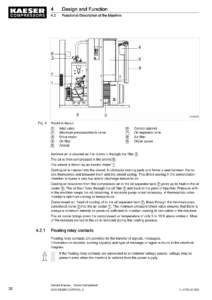
- 4 Design and Function — enclosure, machine function, safety devices, floating relay contacts, operating panel SIGMA CONTROL 2, operating modes and control modes, options, machine mountings
- 5 Installation and Operating Conditions — ensuring safety, installation conditions, determining location and clearances, ensuring the machine room ventilation, exhaust duct design, operating the machine in a compressed air system
- 6 Installation — ensuring safety, reporting transport damage, connecting the machine with the compressed air network, connecting the external pressure transducer, making the power supply connection, changing main voltage connections, anchoring the machine, connecting the external heat recovery system
- 7 Initial Start-up — ensuring safety, instructions before commissioning or re-commissioning, checking installation and operating conditions, setting the overload protection relay, pouring cooling oil into the air end, activating and deactivating the MODULATING control, starting the machine for the first time, setting the set point pressure, checking the door interlock switch, setting the display language
- 8 Operation — switching on and off, switching off in an emergency and switching on again, switching on and off from a remote control center, using the timer for switching on and off, interpreting operation messages, acknowledging alarm and warning messages
- 9 Fault Recognition and Rectification — basic instructions, other faults
- 10 Maintenance — ensuring safety, following the maintenance plan, logging maintenance work, resetting maintenance interval counters, regular maintenance tasks, cooling oil changing interval, regular service tasks, cooler filter mats, control cabinet filter mat, cooler maintenance, air filter maintenance, compressor motor maintenance, maintaining the drive belt, testing the safety relief valve, checking the overheating safety shutdown function, testing the EMERGENCY STOP push button, checking the cooling oil level, venting the machine, replenishing the cooling oil, changing the cooling oil, changing the oil filter, changing the oil separator cartridge, documenting maintenance and service work
- 11 Spares, Operating Materials, Service — nameplate, ordering consumable parts and operating fluids, KAESER AIR SERVICE, spare parts for service and repair
- 12 Decommissioning, Storage and Transport — temporary and long-term decommissioning, packing, storage, transport with a forklift truck, transport with a crane, disposal, battery disposal
- 13 Annex — pipeline and instrument flow diagram (P+I diagram), P+I diagram for MODULATING control mode, dimensional drawing, electrical diagram
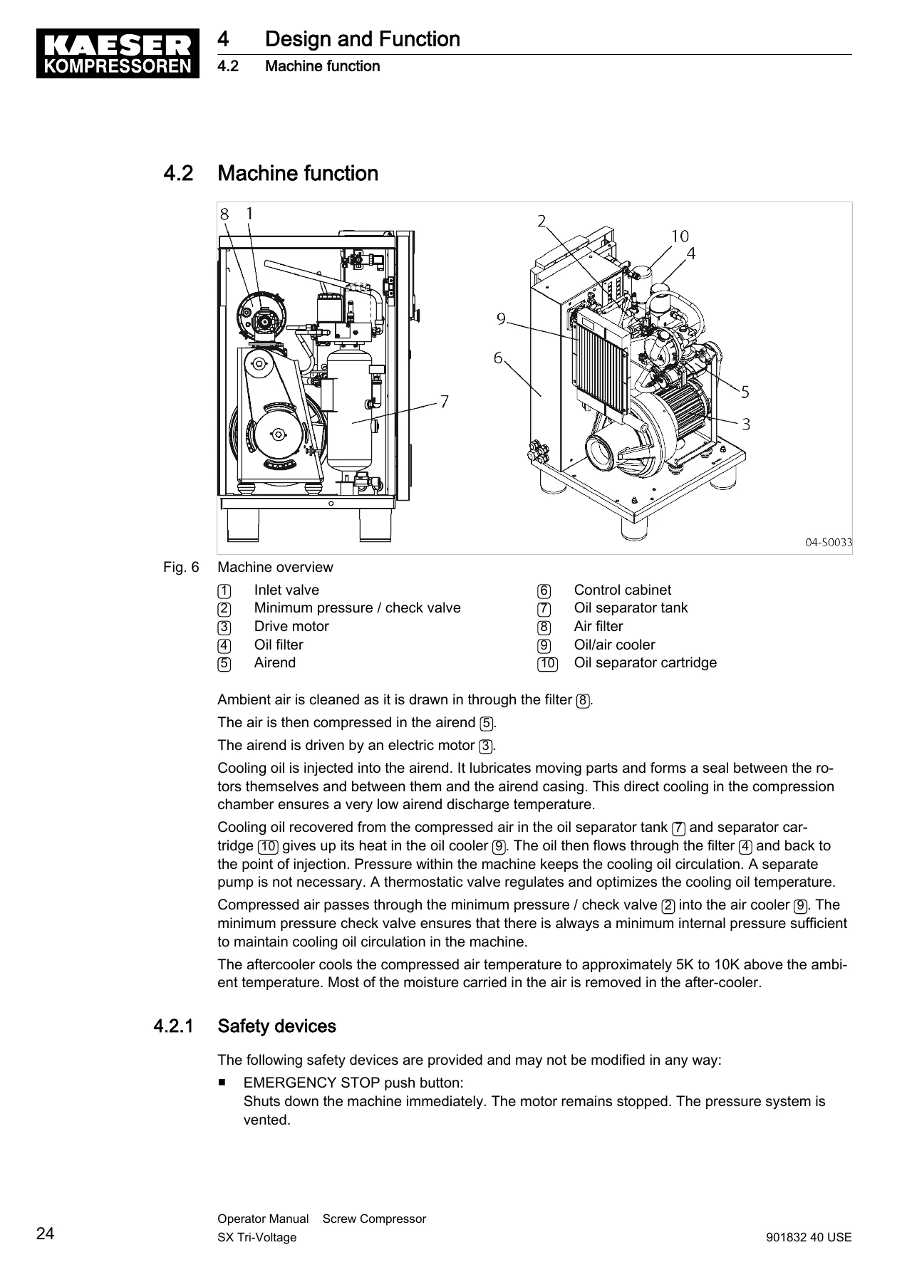
What makes this manual useful is that it does not stop at the operating panel. It carries the reader through the whole service life of the SX package: the technical data chapter fixes the ratings you need before you touch anything, the design chapter explains how the airend, oil separator tank, minimum pressure/check valve and thermostatic valve interact, and the maintenance chapter lays out the tasks in the order and at the intervals KAESER expects. Torque-adjacent details such as overload protection relay settings per supply voltage, cooling oil charge quantities, safety relief valve activating pressures and oil change intervals are all present as tables, which is what you want when you are standing at the machine rather than guessing.
Using the SX Tri-Voltage Manual in the Workshop
The SX 3, SX 4, SX 5 and SX 7.5 share the same package layout, so the exploded machine overview, the enclosure diagrams and the P+I diagrams apply across the range. Where a value differs by model or by supply voltage, the manual splits it into SX 3 / SX 4 / SX 5 / SX 7.5 columns rather than giving a single generic figure. That structure runs through the weight table, the temperature table, the ambient conditions, the ventilation flow rates, the free air delivery figures, the compressor motor ratings and the power supply specifications for 208V, 230V and 460V three-phase supplies.
The safety and responsibility chapter is substantial and worth reading before any intervention. It covers the dangers of electricity, stored compression forces, spring-loaded valves, rotating components, high surface temperatures, noise and operating fluids, then defines the danger areas around the machine during transport, installation and operation. The working life of the safety functions is also stated — the resistance thermometer, EMERGENCY STOP push button, main contactor and door interlock switch are given a defined service life, and the manual tells you to have them replaced by a KAESER service representative when that life is reached.
Control, Operation and Diagnostics
The SIGMA CONTROL 2 operating panel gets its own treatment, with the key layout, indicator LEDs, RFID sensor field and the machine operating modes STOP, READY, LOAD and IDLE explained. The control modes DUAL, QUADRO and VARIO are described together with guidance on which mode suits a compressor running as a base load, intermediate load or peak load machine. Where the optional MODULATING control is fitted, the manual explains how the proportional controller varies the inlet valve opening and how to switch that regulation on or off using the shut-off valve. Fault recognition is handled through the message types — warning, alarm, system and diagnostic — followed by a fault table listing other problems that do not raise an indication, such as the machine not running, running without producing air, cooling oil appearing at the air filter or excessive cycling between LOAD and IDLE, with the likely cause and remedy for each.
Maintenance and Fluid Service
The cooling oil side of the SX compressor is covered in detail because it drives reliability and air quality. The manual explains the role of the lubricant as a sealant and coolant in the airend, lists the KAESER lubricant families with their recommended change intervals, and gives the total charge and topping-up volumes. Procedures for venting the machine before work, topping off, draining oil from the separator tank and from the oil cooler, changing the oil filter and changing the oil separator cartridge are all broken down step by step, including the alternative method that uses an external compressed air source when the machine cannot be run. Cooler and filter mat cleaning, air filter replacement, drive belt inspection and replacement, safety relief valve testing, overheating shutdown verification and EMERGENCY STOP testing round out the maintenance chapter. A maintenance log table is provided so the work can be recorded against operating hours.
Reference Material in the Annex
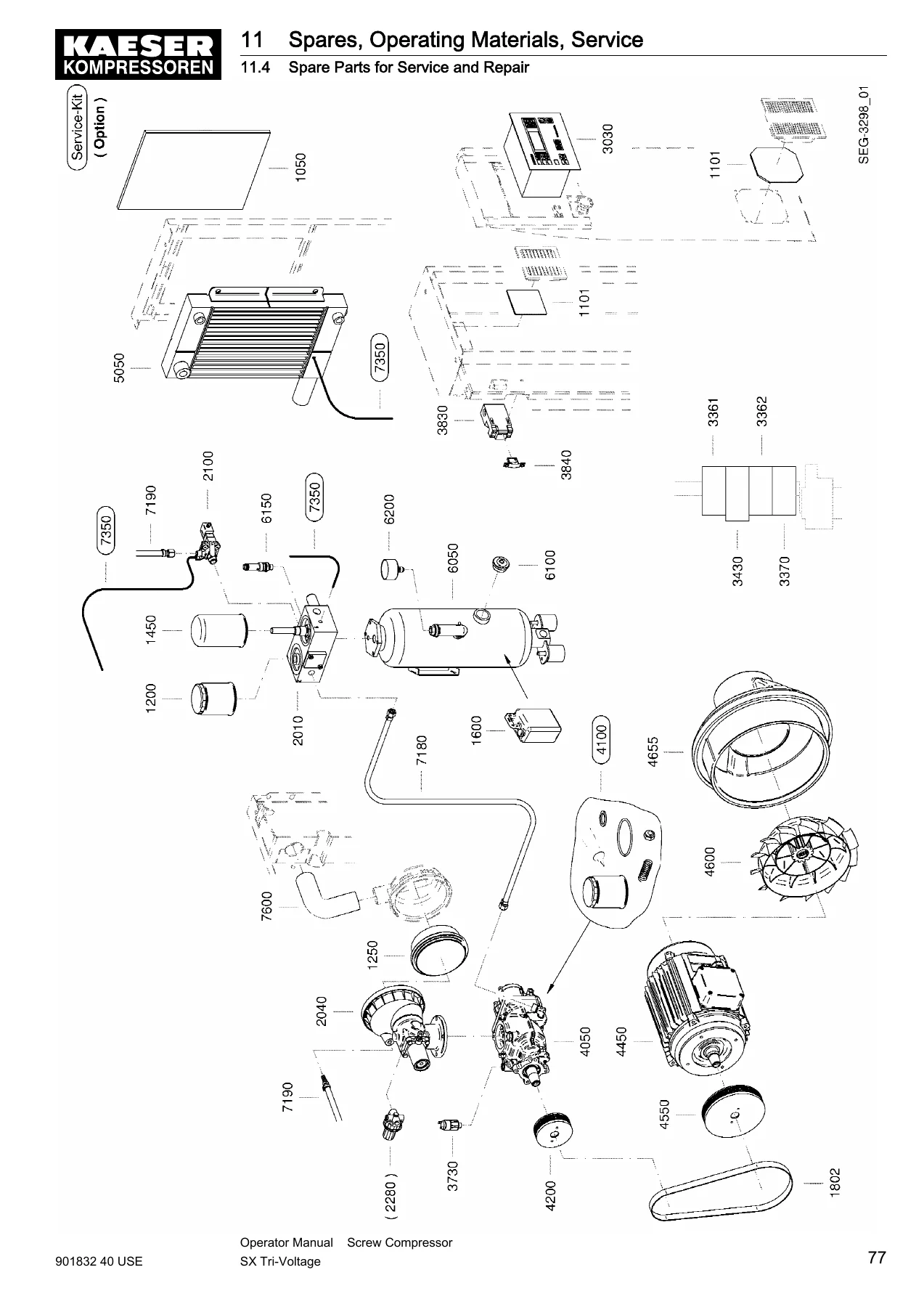
The annex carries the pipeline and instrument flow diagrams in both standard and MODULATING control versions, a dimensional drawing with the connection port positions and clearances, and the electrical diagram set including the terminal connection tables and the control transformer voltage connection diagrams for 208V, 230V and 460V. The spare parts chapter includes an illustrated parts overview with item numbers covering the filter mats, oil filter, air filter element, oil separator cartridge, valve block, inlet valve, SIGMA airend, drive motor, pulleys, cooler, oil separator tank and hose lines, together with the consumable part list. That combination lets you identify a component visually and order it by item number in the same sitting.
Who This Manual Suits
Operators who need to run the SX compressor correctly, maintenance technicians handling scheduled service, and anyone commissioning a tri-voltage SX package or recommissioning one after storage will find the material directly applicable. The manual also sets out the special measures required after storage periods of three months, twelve months and thirty-six months, so machines that have been sitting idle can be brought back into service without skipping the steps that protect the airend and motor bearings.
Get the Kaeser SX Screw Compressor Operator Manual
With this manual on hand you can commission an SX 3, SX 4, SX 5 or SX 7.5 compressor, set the overload protection relay for the supply voltage actually present, run the machine through its first start, set the set point pressure, and carry out the full maintenance schedule from weekly oil level checks through to cooling oil, oil filter and oil separator cartridge changes. You can vent the machine safely before opening anything, test the safety relief valve and the overheating shutdown, inspect and replace the drive belt to the tension markings, and work from the P+I and electrical diagrams when a fault does not match the standard message list.
Correct procedures and the right specifications are what separate a compressor that runs for years from one that consumes oil, trips on temperature or fails an airend. Having the pressures, charge quantities, relay settings and interval tables in front of you removes the guesswork and keeps the machine inside its performance limits and permitted ambient conditions.
IMAGES PREVIEW
The manual is delivered as an instant PDF download after payment — no shipping, no waiting. Read it on a laptop, tablet or phone in the compressor room, or print the pages you need for the job and keep them with the machine.

Reviews
There are no reviews yet.