
Kalmar DCE 90-180 Forklift Workshop Manual – Complete Service & Repair Guide PDF Download (VDCE02.01GB)
Original price was: $67.95.$44.95Current price is: $44.95.
The complete Kalmar DCE 90-180 Workshop Manual (VDCE02.01GB) covering corrective maintenance, engine, transmission, brakes, hydraulics, electrics and more for the 9-18 tonne forklift range. Instant PDF download.
Description
This is the complete Kalmar DCE 90-180 Workshop Manual, publication number VDCE02.01GB – the heavy-duty corrective maintenance and technical description guide used by professional service technicians for the Kalmar DCE 90-180 forklift truck family. The manual covers the full range of DCE 90-6, DCE 100-6, DCE 120-6, DCE 140-6, DCE 100-12, DCE 120-12, DCE 150-12, DCE 160-6, DCE 160-12, DCE 180-6, DCE 70-32E3 and DCE 70-35E4 trucks, fitted with the Volvo TAD620, Volvo TAD720 or Cummins QSB5.9 six-cylinder diesel engine.
Where the Maintenance Manual covers the routine service schedule, this Kalmar DCE 90-180 workshop manual PDF goes deeper – into corrective maintenance work instructions, component-by-component technical descriptions, system function explanations, and the supplier documentation from the engine, transmission and drive axle manufacturers. Each function group is broken down into its sub-functions with illustrated procedures for the components that serve them.
File Details
- Manual type: Workshop Manual (corrective maintenance and technical description)
- Brand: Kalmar Industries
- Machine series: DCE 90-180 forklift truck
- Publication number: VDCE02.01GB
- Language: English
- Page count: Approximately 559 pages
- Format: PDF (single file, printable)
Chapters Covered
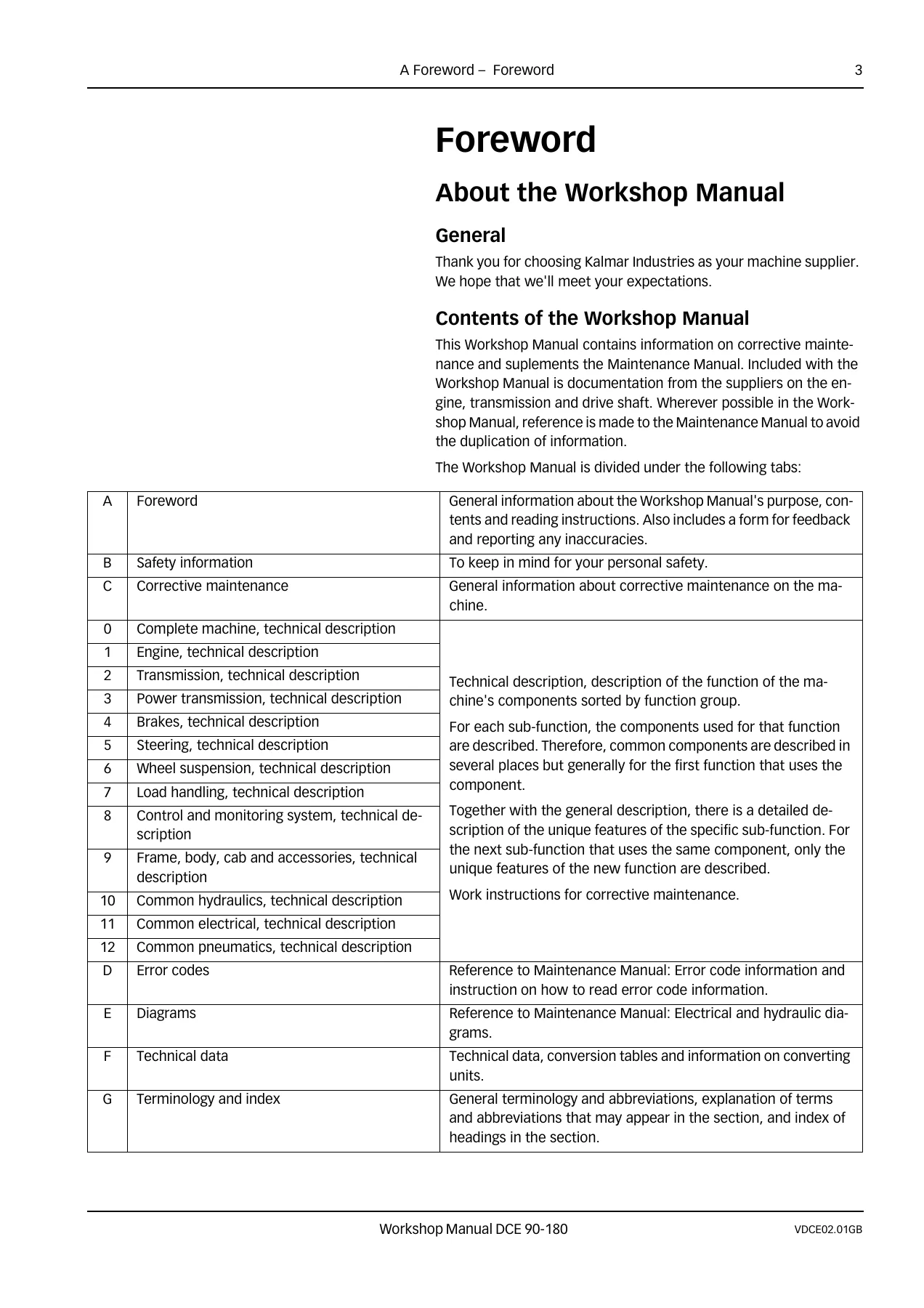
- A Foreword
- B Safety
- C Corrective Maintenance
- 0 Complete Machine
- 1 Engine
- 2 Transmission
- 3 Driveline / Axle
- 4 Brakes
- 5 Steering
- 6 Suspension
- 7 Load Handling
- 8 Control System
- 9 Frame, Body, Cab and Accessories
- 10 Common Hydraulics
- 11 Common Electric
- D Error Codes
- E Diagrams
- F Technical Data
- G Terminology and Index
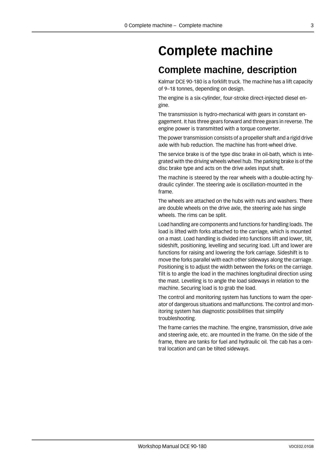
Complete Machine (Tab 0)
Description of the Kalmar DCE 90-180 as a whole: six-cylinder four-stroke direct-injected diesel engine, hydro-mechanical transmission with three forward and three reverse gears through a torque converter, front-wheel drive via propeller shaft and rigid drive axle with hub reduction, oil-bath disc service brakes integrated into the wheel hubs, disc-type parking brake on the drive axle input shaft, rear-wheel double-acting hydraulic steering cylinder, and a sideways-tilting cab. Lift capacity is 9-18 tonnes depending on design.
Engine (Tab 1)
Full technical description and corrective maintenance for the Volvo TAD620, Volvo TAD720 and Cummins QSB5.9 engines. Covers controls and instrumentation, fuel system (tank, filter, pre-filter, pump, overflow valve, injectors, fuel cooler, level sensor, pipes and hoses), additional exhaust gas cleaning system including particle filter, air intake and exhaust (air cleaner, turbo, exhaust system, intercooler, boost pressure and charge-air temperature sensors, crankcase ventilation, charge-air hoses), cooling system (coolant pump, thermostat, radiator, expansion tank, cooling fan, oil cooler, coolant level make-contact, coolant temperature sensor, plug-in heater), lubrication (oil sump, oil pump, oil pressure sensor, oil filter, reducer valve), engine control system (ECU 794, engine speed sensor, cable harness), preheating and start/stop devices.
Transmission (Tab 2)
Torque converter / clutch system with flex plates, pump rotor, stator, turbine rotor and speed/temperature sensors. Mechanical transmission components: gear pack, disc clutches, power take-off, input shaft, transmission control valve block, turbine speed sensor, shaft speed sensor, output shaft and output speed sensor. Lubrication (oil pump, oil pressure sensor, oil cooler, oil filter) and cooling (cooling oil pump, oil temperature sensor). Control system transmission including ECU 793 with display and menus, operating modes (normal, self-test, limp-home, shut-down), fault diagnosis and cable harness.
Driveline and Axle (Tab 3)
Propeller shaft with universal joints and cross-tooth connections. Drive axle with hypoid differential, full-floating drive shafts and planetary hub reduction. Includes axial play adjustment.
Brakes (Tab 4)
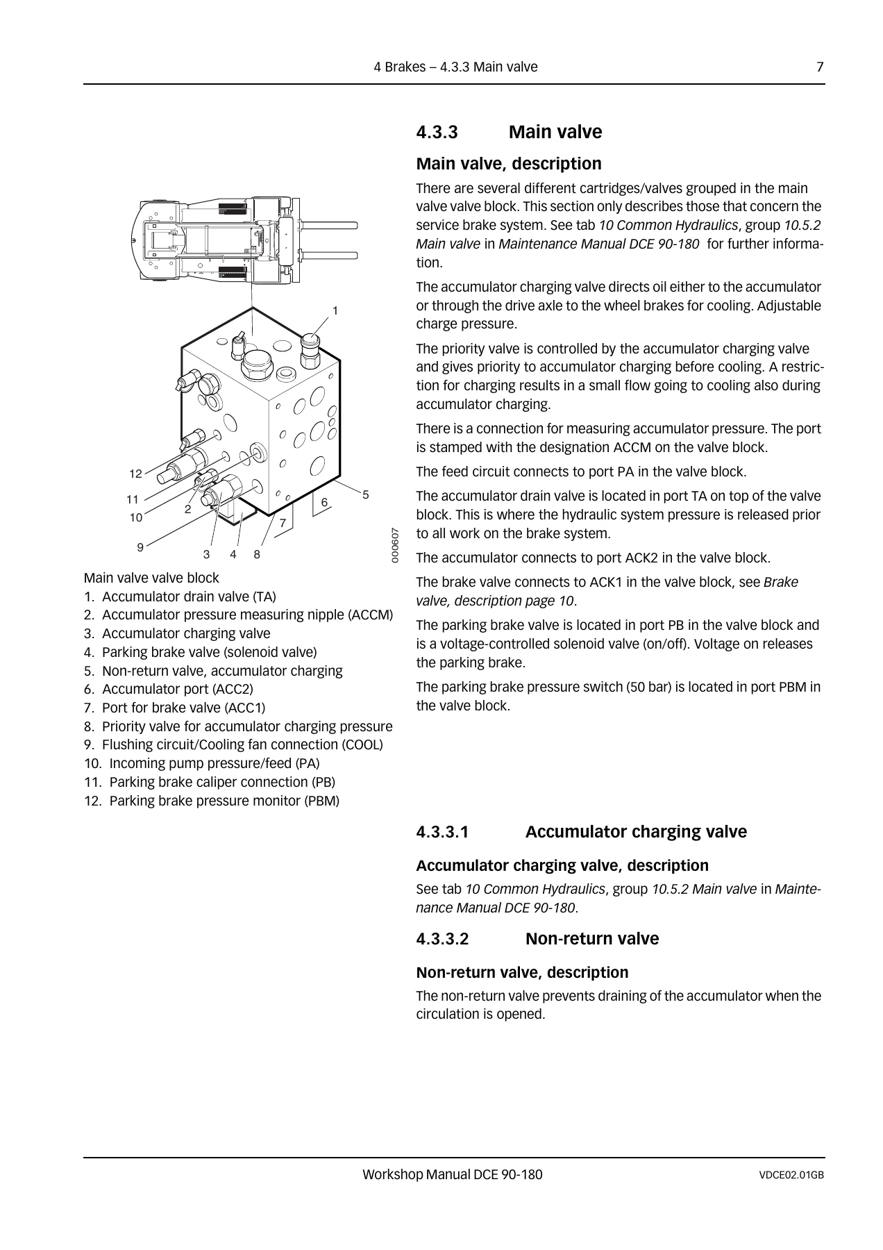
Service brake system including pump 3 for accumulator charging and cooling circuit, high-pressure filter, main valve block, accumulator, brake valve, distribution block, break contact disengagement, break contact low brake pressure, make-contact brake lights, wet disc wheel brakes (disc pack and brake cylinder). Parking brake system: parking brake valve, spring-actuated parking brake unit with calliper, pads and disc, parking brake break contact. Temperature control, filtration and brake fluid.
Steering (Tab 5)
Controls and instrumentation: steering wheel and steering column, mini-wheel, steering lever. Power-assisted system: pump 4 for mini-wheel/lever steering, main valve priority valve, steering valve with integrated shock and anti-cavitation valves, double-acting steering cylinder with through piston rod, steering axle cradle, link arm, wheel spindle, wheel hub, sensor wheel angle, directional valve mini-wheel/lever steering, sensor steering wheel angle, filter, pressure reducing valve, pressure limiting valve and directional valve for reversible operator’s seat.
Suspension (Tab 6)
Suspension mounting: steering axle cradle, wheel spindle with roller bearings, wheel hub with tapered roller bearings. Tyre system: tyres, split rims, nuts and washers. Safety warnings for tyre handling and inflation.
Load Handling (Tab 7)
Controls and instrumentation, control lever. Lifting/lowering: hydraulic oil pump, accumulator, main valve, lift cylinder with end-position damping, accumulator damping, duplex standard and duplex/triplex freelift masts, mast wheels, chains, chain wheels, fork carriage, load control valve, pipes and hoses. Sideshift, positioning (with flow divider), tilt (with over-centre load holding valve), levelling and load carrying (forks). Hydraulic cylinder repair procedures including seal fitting, piston rod repair and steering cylinder disassembly.
Control and Monitoring System (Tab 8)
Terminal EDU 795 electronic display unit, monitoring functions (ETC, automatic shifting, reverse lock-out, feedback and non-feedback lever steering, mini-wheel, electro-hydraulic servo, scale, monitoring, pre-selected lift height, vertical hold, OptimumSpeed and OptimumRev). Error codes, diagnostics for ECUs 790, 793, 795 and 796, settings and calibration procedures for each function, and software.
Frame, Body, Cab and Accessories (Tab 9)
Multi-function lever, seat heating switch, indicator light. Restraints, seat (cushions, heating coils, shock absorbers, air suspension, compressor, mechanical adjustment, passenger and reversible seats), HVAC (dampers, vents, cab fan, filters, heat exchangers, water valve, AC compressor, thermostat, condenser, expansion valve, temperature sensors, TCS control unit, air distributor), wiper/washer system, lighting system, communication system, entertainment/communication, glass/windows/mirrors, cab structure and suspension, cab interior, frame, body structure (fenders, engine hood, footstep, counterweights, battery compartment), central lubrication and paint/coatings.
Common Hydraulics (Tab 10)
Security valves, tanks and accumulators, pumps (gear pump with fixed displacement, axial piston pump with variable displacement), hoses/pipes/valves (main valve, priority valve, shuttle valve, proportional valve), and temperature control, cleaning and hydraulic oil including tank heater, hydraulic oil cooler, oil temperature sensor, cooling fan make-contact, thermal bypass valve, breather filter, high-pressure filter and hydraulic oil specifications.
Common Electric (Tab 11)
Hour meter, battery disconnector, fuses, start battery, alternator, distribution of electricity (voltage feed, electrical distribution box, control units ECU 790, EDU 795, ECU 796, ECU 793, ECU 794 with full PIN-out tables), start-up electrical system, cable harness, CAN-bus, redundant CAN-bus and CAN-bus driveline.
Error Codes (Tab D)
Complete error code tables for engine ECU 794 (Cummins QSB5.9), transmission ECU 793 (TE13000 and TE17000), and control system ECUs 790, EDU 795 and 796, with descriptions, limitations and recommended actions. Includes reading out error codes with and without KCS.
Diagrams (Tab E)
Compiled hydraulic diagrams A40750.0100 through A40750.0900 covering brake, steering, load handling, pumps and electrical servo variations, plus electrical circuit diagrams listing (drawing numbers and circuit contents for gearshifting, sensors, wipers, climate, cab, lighting, working lights, throttle, datacom and more).
Technical Data (Tab F)
Dimensions and weights for the complete DCE 90-180 range, general tightening torques (metric, fine metric and UNC), oil and lubricant recommendations, conversion tables for SI units, length, area, volume, weight and pressure. Engine technical data (output, torque, cylinder count, alternator, batteries), fuel system, exhaust cleaning, cooling, lubrication, control system, transmission, driveline/axle, brakes, steering, suspension, tyres, HVAC, wipers, lighting, communication, entertainment, common hydraulics and common electric.
Terminology and Index (Tab G)
Glossary of technical terms and abbreviations used throughout the manual, plus a full index mapping each subject to its tab and function group.
Who This Kalmar DCE 90-180 Workshop Manual Is For
This Kalmar DCE 90-180 repair manual is intended for trained service technicians, fleet maintenance teams, and technically capable operators responsible for keeping DCE 90-180 forklift trucks working safely and reliably. It assumes standard workshop tools and workshop conditions. Where a job requires a specific tool, a lifting device, or a certified technician (for example air conditioning work), the manual says so.
The information in the PDF corresponds to the machine design at time of delivery from Kalmar Industries. Kalmar reserves the right to modify specifications and equipment without notice, and customizations may introduce variations, so the manual reflects the design and appearance at the time of publication.
Why This Manual Matters
These are 9-18 tonne industrial forklift trucks working with heavy loads, high hydraulic pressures and accumulated brake pressure. Correct torque values, seal fitting technique, accumulator depressurisation steps and error-code diagnosis are not optional – they are what separates a repair that lasts from one that fails. This workshop manual gives you the manufacturer’s own procedures for each function group, including the diagnostic and calibration routines for the KCS control system.
Whether you are replacing a wheel brake disc pack, chasing a transmission fault code, resealing a lift cylinder or calibrating the ETC servo motor, the relevant procedure, technical description and reference values are in the same PDF.
IMAGES PREVIEW
Instant PDF Delivery – Print or Read Anywhere
The Kalmar DCE 90-180 workshop manual is delivered as an instant digital download after purchase. There is no shipping, no waiting, and no physical book to keep track of. Use it on the shop laptop, tablet or phone, or print the pages you need and take them straight to the machine. Keep a full copy in the workshop and a second copy on your device for callouts.
Get the complete Kalmar DCE 90-180 Workshop Manual VDCE02.01GB now and put the full corrective maintenance, technical description and error code reference for the DCE 90-180 forklift range at your fingertips.
Reviews
There are no reviews yet.