
Kalmar DCG 90-180 Forklift Maintenance Manual – 9-18 Tonne Truck PDF
Original price was: $39.95.$24.95Current price is: $24.95.
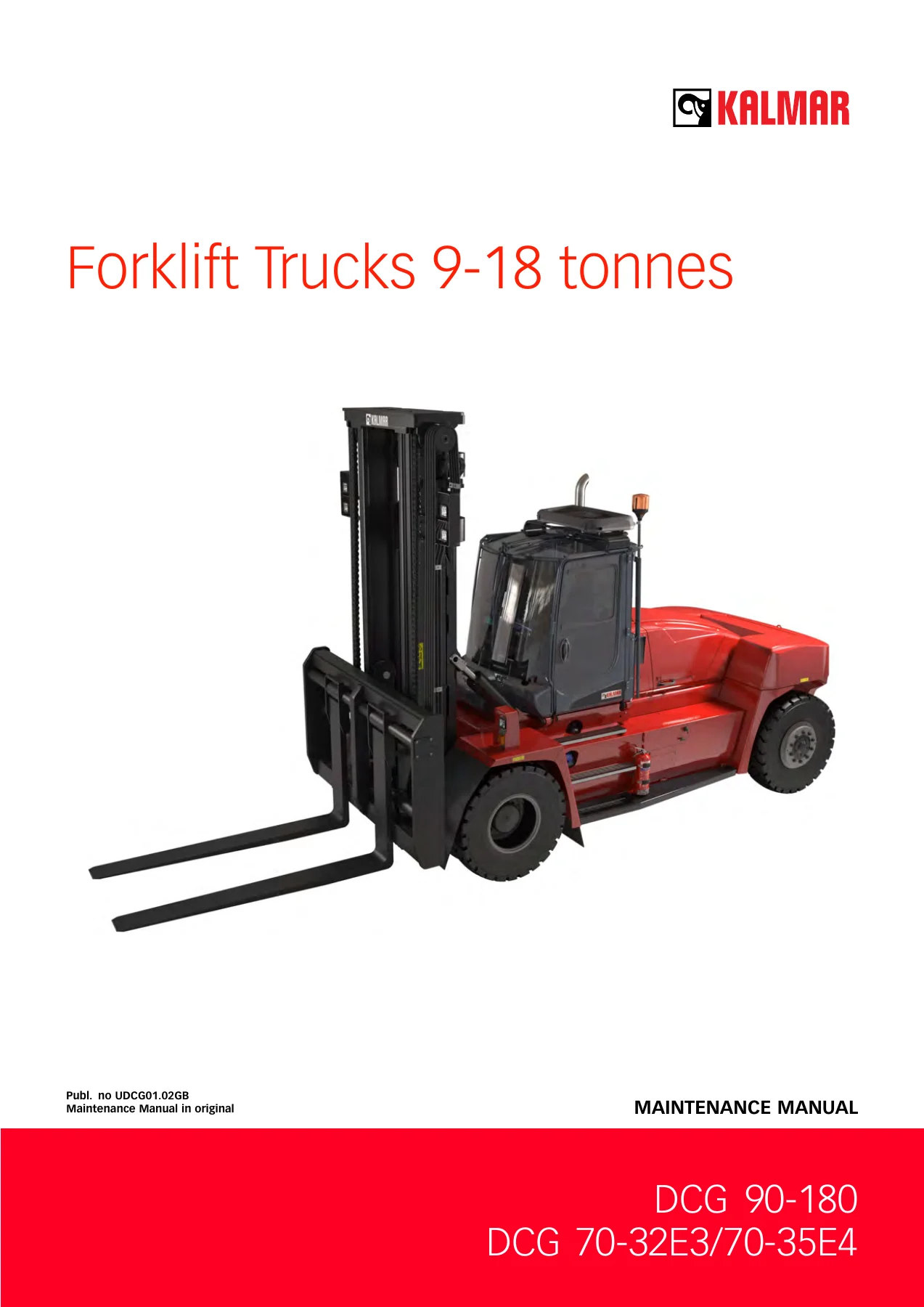
Complete Kalmar DCG 90-180 maintenance manual for the 9 to 18 tonne forklift range. Covers the 500h, 1000h and 2000h service schedule, all four engine alternatives, transmission, brakes, steering, load handling, hydraulics, electrics and the crack inspection programme. Instant PDF download.
Description
Kalmar DCG 90-180 Forklift Maintenance Manual
This is the full maintenance manual for the Kalmar DCG 90-180 heavy forklift range, the 9 to 18 tonne trucks built by Cargotec. It is the document issued to the workshops that look after these machines, and it covers the whole preventive maintenance programme plus the checks, adjustments and component work a technician needs to keep a DCG 90-180 running reliably.
The manual is organised into function groups numbered 0 to 12, with lettered sections A to G carrying the information that applies across several groups, such as safety, technical data and terminology. That structure makes it fast to navigate: if you are working on the brakes you go to group 4, if it is the mast chains it is group 7.2.8, and so on.
File Details
- Manual type: Maintenance manual
- Brand: Kalmar (Cargotec Sweden AB)
- Model series: DCG 90-180, 9-18 tonnes
- Publication number: UDCG01.02GB
- Language: English
- File format: PDF
- Page count: 372 pages
- Illustrations: Component location drawings, lubrication point diagrams, exploded views and photographic check points
Chapters Covered
- A Foreword – about the maintenance manual, reading instructions, product alternatives, optional equipment, machine card, documentation and feedback
- B Safety – general safety information, service position, depressurising the hydraulic system, oils, fuel system, AdBlue, clothing, several mechanics on the same machine, working under the machine, lifting heavy components, vibrations, noise, solvents, fire and explosion risks, fluid or gas under pressure, coolant, refrigerant, air pollution, tensioned springs, electrical system, rotating components, tyres and rims, lifting equipment, welding, spare parts, non-ionised radiation, environment
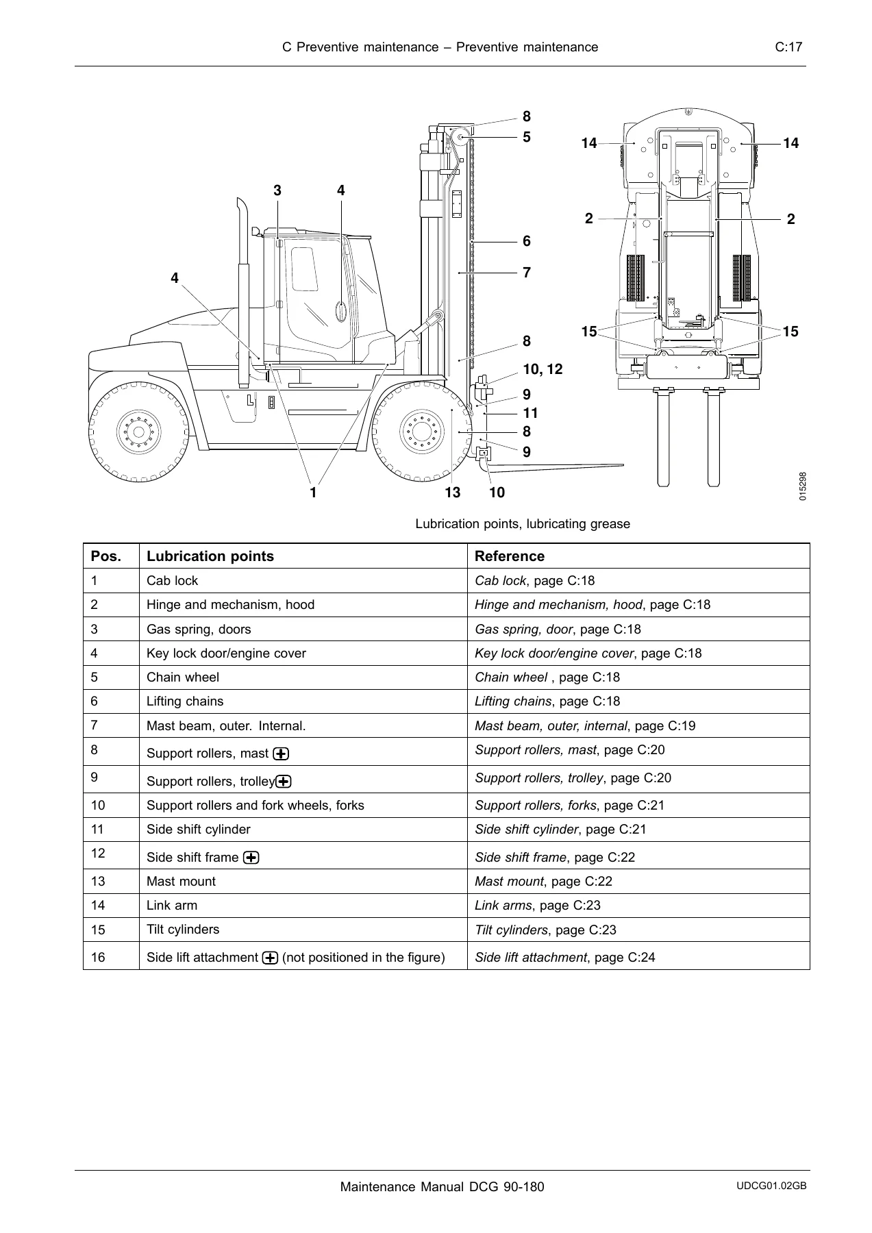
- C Preventive maintenance – general, work instructions, check and service log, service schedule, washing, lubricating 500h, lubricating 1000h, checking for cracks
- 0 Complete machine – description of the machine and its systems
- 1 Engine – fuel system (fuel tank, fuel prefilter, fuel filter, AdBlue tank, AdBlue filter in the pump unit, screen in AdBlue tank), engine mechanical parts, valve mechanism, crank mechanism, air intake and exhaust outlet, air cleaning system, exhaust system, intercooler, crankcase ventilation, cooling system (coolant pump, radiator and expansion tank, coolant), lubrication system, engine control system, ignition/heating, start/stop
- 2 Transmission – mechanical transmission, lubrication system, cooling system, transmission control system, transmission calibration
- 3 Driveline/Axle – propeller shaft, drive axle
- 4 Brakes – controls and instruments, brake pedal, power-assisted brake system, brake valve, parking brake system, parking brake unit, temperature control, cleaning and hydraulic oil
- 5 Steering – power-assisted system, link arm, wheel angle sensor, steering wheel angle sensor
- 6 Suspension – steering axle cradle, steering spindle, wheel hub, tyres and rims
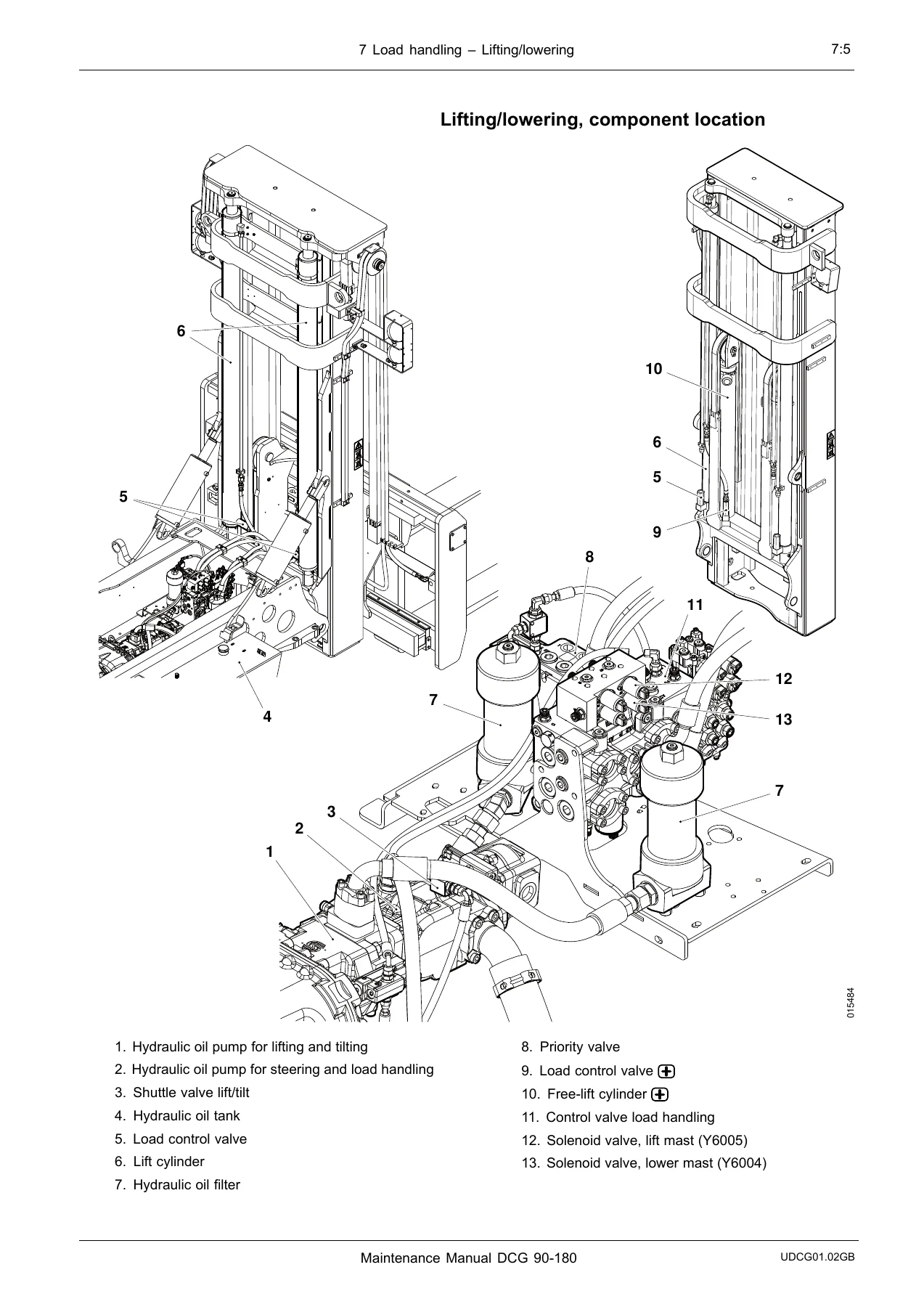
- 7 Load handling – lifting/lowering, mast, chains, side shift, side shift cylinder, spreading, tilt, tilt cylinder, levelling, load carrier, lifting forks, side lift attachment and twistlocks
- 8 Control system – monitoring functions, bypass, speed limitation, service indicator, load sensor
- 9 Frame, body, cab and accessories – controls and instruments, safety and emergency equipment, seats, heating/ventilation/air conditioning, fresh air filter, condenser unit, moisture filter, recirculation filter, wiping and cleaning of windows, lighting system, signalling system, glass/windows/mirrors, construction and suspension of cab, cab tilting, cab interior, frame, body structure, counterweights, central lubrication, paint/coatings
- 10 Common hydraulics – safety valves, tanks and accumulators, accumulator, pumps, hoses/pipes/valves, temperature control and cleaning, hydraulic oil cooler, breather filter, hydraulic oil filter, hydraulic oil
- 11 Common electrics – electrical protection, fuses, batteries, start battery, alternator, distribution of electricity, voltage feed, control units, communication, CAN bus
- 12 Common pneumatics
- D Error codes, E Diagrams, F Technical data, G Terminology and index
Read as a whole, the manual gives a technician the complete maintenance picture for the DCG 90-180: the three-tier service schedule that runs on 500 hour, 1000 hour and 2000 hour cycles, the lubrication rounds split between the 500h and 1000h intervals, and the torque and adjustment values that go with each job. Every procedure is written as a numbered sequence with the safety warnings that apply to it placed immediately alongside, which is what makes this a working document rather than a reference book. Cross references point to the function group and page where a component is described, so you can move between a service action and the description of the part it affects without losing your place.
What the Scheduled Service Covers
The service schedule chapter is the part most owners will use first. It lays out exactly what is checked, cleaned, lubricated, adjusted and replaced at each interval, grouped by function group. On the engine side that means fuel prefilter draining, fuel filter changes, AdBlue filter and screen replacement, valve clearance checks, air filter main and safety cartridges, crankcase ventilation filters, drive belts and belt tensioners, radiator and intercooler cleaning, and coolant condition. Running down through the machine it covers transmission oil and filter changes with the calibration step that follows, drive axle oil levels and drainage at the hubs and differential, brake pedal and brake pressure checks, parking brake pad thickness, link arm bearings, steering sensors, steering axle cradle bushings, steering spindle and wheel hub play, tyre pressure and wheel nut torque, mast suspension, side support, lifting chains, tilt and side shift cylinders, lifting forks, twistlocks and attachment sensors, cab mounts and doors, the air conditioning filters and condenser, hydraulic accumulator precharge, hydraulic oil sampling, fuses and batteries.
The crack inspection chapter deserves a mention on its own. It shows the specific welds to check on the mast mounts, tilt mounts, drive axle mounts, lifting forks, trolley, counterweight box, steering axle mounts and frame beam, with photographs marking each area and a two-stage magnetic particle and penetrating fluid method for confirming a suspected crack. That is the sort of information you do not get from a generic service book.
Engine Alternatives Covered
The manual covers four engine options and gives separate procedures where they differ, particularly for fuel system bleeding, valve clearance adjustment and cooling system cleaning. The alternatives are the Volvo TAD761VE 160 kW Stage 3B/Tier 4i, the Cummins QSB6.7 129 kW Stage 3A/Tier 3, the Cummins QSB6.7 129 kW Stage 3B/Tier 4i and the Cummins QSB6.7 164 kW Stage 3B/Tier 4i. Exhaust aftertreatment content covers SCR with AdBlue on the Volvo, DOC on the Cummins 129 kW Stage 3B/Tier 4i, and DPF with EGR on the Cummins 164 kW Stage 3B/Tier 4i, including the particulate filter removal and cleaning procedure.
Control System, Diagnostics and Calibration
Beyond the mechanical work, the manual walks through the machine’s electronic control system from the operator’s perspective and the technician’s. It explains the monitoring functions, the bypass safety system and when it may legitimately be used, the speed limitation logic, and how to reset the service indicator through the display menus. The transmission calibration procedure is given step by step, including the heat mode used to bring the transmission oil up to temperature before calibration and the main code and subcode tables used to interpret the result. Load sensor calibration for the duplex, triplex free-lift and chain tightener mast variants is also documented. Hydraulic pressure checking is covered with the measuring outlet for each circuit – servo pressure, steering and load handling pump pressure, lift and tilt pump pressure, brake system pump pressure, steering pressure and accumulator charging – with the values to compare against the machine’s pressure plate.
Who This Manual Is For
This is a maintenance manual rather than a full workshop manual. Cargotec splits the documentation so that preventive maintenance sits here, while in-depth repair and overhaul instructions sit in the workshop manual. If you are planning a service, a lubrication round, a crack inspection, a filter and fluid change programme, a brake or parking brake pad replacement, a chain check and adjustment, a valve clearance check or a hydraulic pressure test, this manual has the procedure. If you are stripping a transmission or rebuilding an axle, the manual will tell you what the component does and where it sits, but the rebuild itself is a workshop manual job.
Covered Machine Variants
The data tables and specification chapters reference the DCG 90-6, DCG 100-6, DCG 120-6, DCG 127-6, DCG 140-6, DCG 150-6, DCG 100-12, DCG 120-12, DCG 150-12, DCG 160-6, DCG 160-9, DCG 160-12 and DCG 180-6 models, along with the DCG 70-32E3 and DCG 70-35E4 entries that appear in the capacity and volume tables. Lifting capacities run from 9 tonnes through to 18 tonnes depending on version. The machines use the ZF 3WG161 or ZF 3WG171 transmission and a Kessler D81 drive axle, with a hydro-mechanical transmission giving three forward and three reverse gears.
Get the Kalmar DCG 90-180 Maintenance Manual
IMAGES PREVIEW
With this Kalmar DCG 90-180 forklift maintenance manual on hand you can run the full service schedule to the intervals Cargotec specifies, torque every fastener to the figure the manual gives, and inspect the structural welds that matter on a truck of this size. Following the documented procedures and specifications is what keeps a 9 to 18 tonne forklift safe to operate and stops small faults turning into dropped loads, seized bearings or cracked mast mounts. The file is delivered as an instant PDF download after payment – no shipping, no waiting, readable on a laptop, tablet or phone in the workshop, and printable if you prefer a paper copy on the bench.
Reviews
There are no reviews yet.