
Kalmar DCG330-12 Forklift Parts Catalogue B20700410 – 2021 PDF
Original price was: $39.95.$24.95Current price is: $24.95.
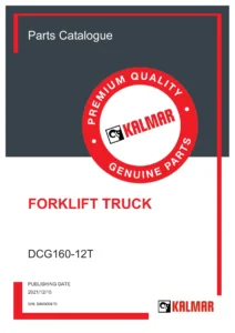
Kalmar DCG330-12 forklift parts catalogue for machine S/N B20700410, published 2021/06/30. This 806-page PDF provides illustrated component breakdowns, part numbers, descriptions, quantities, assembly references, maintenance kit information, hydraulic and electrical coverage, and a numerical parts register.
Description
Kalmar DCG330-12 Forklift Parts Catalogue B20700410 – 2021 PDF
The Kalmar DCG330-12 Forklift Parts Catalogue B20700410 – 2021 PDF is a detailed parts reference for the DCG330-12 forklift truck identified by serial number B20700410. Published on 2021/06/30, the catalogue is structured around the machine’s major assemblies and uses illustrated parts pages together with corresponding parts lists to identify components throughout the truck.
The catalogue explains that its information applies to the machine model and serial number shown on the front page. Each illustrated assembly is followed by a parts list showing position numbers, part numbers, descriptions, quantities, units and notes. The result is a practical reference for locating a component in an assembly, matching it to the correct listed part number and understanding how related items are grouped within the machine.
File Details
- Manual type: Parts Catalogue
- Brand: Kalmar
- Model: DCG330-12
- Machine serial number: B20700410
- Publishing date: 2021/06/30
- Language: English
- Page count: 806 pages
- File format: PDF
Parts Information for the DCG330-12 Configuration
This Kalmar DCG330-12 parts catalogue goes beyond a simple list of generic component names. The machine-specific sections identify the major fitted assemblies and then break many of them down through dedicated drawings and parts lists. The catalogue identifies the complete engine as B6.7 168kW STAGE V and the gearbox as DANA 340FTE17312-81. The drive axle is identified as a complete Axletech unit.
The load-handling pages record a mast with a lifting height of 4500 mm, a lifting carriage with a width of 3400 mm, and a fork/roller entry sized 300x110x2400. The suspension section identifies Continental tyres marked 16.00*25/32 together with a SANKEY 16.00X25 rim. The urea system includes a tank listed with a 35 L volume. These machine-specific details help distinguish the configuration represented by this catalogue when checking assemblies and ordering references.
How the Illustrated Parts Catalogue Works
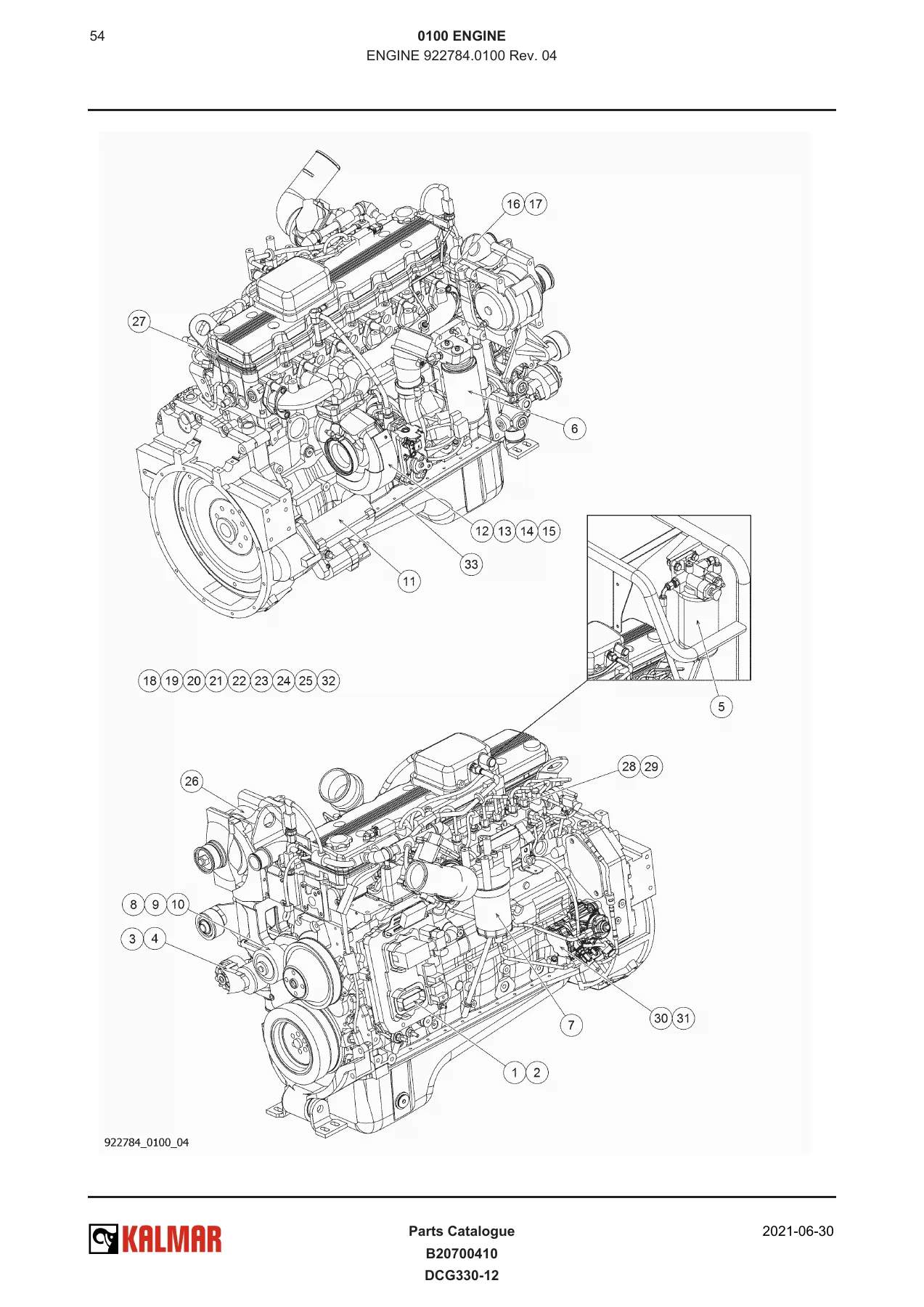
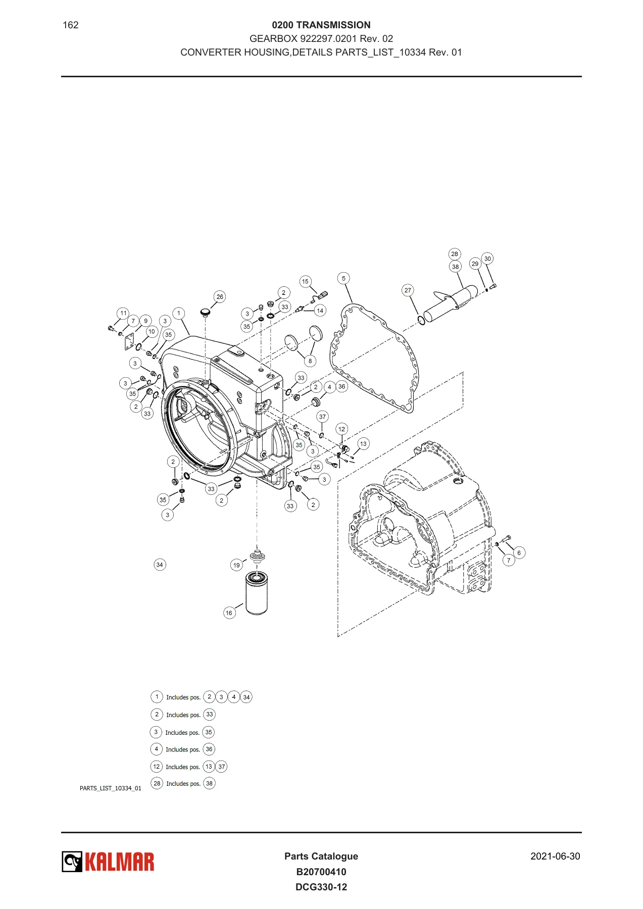
The document is arranged as paired illustration and parts-list pages. Illustration pages use exploded views or plane views with numbered positions. The following parts list connects those position numbers to the applicable part number, description and quantity. Where assemblies contain further subcomponents, the catalogue can continue into additional subassembly or PARTS_LIST sections.
This structure is especially useful when a component is known visually but its exact ordering reference is not. Instead of working only from a name, the user can follow the drawing position into the adjacent list, identify the assembly number and revision shown on the page, and then review the individual component entries. The catalogue also includes a numerical register beginning near the end of the document for another route into the part-number information.
A machine-card section is part of the catalogue structure as well. The catalogue instructions describe the machine card as a record of basic machine information, major component information and revisions, serial numbers for selected components, and comments associated with the machine.
Preventive Maintenance and Service Parts
Preventive-maintenance parts are included early in the catalogue. The service-kit information identifies the B6.7 168kW Stage 5 engine together with the DANA 340FTE17312-81 transmission and lists filter kits for the first 500H service as well as 500H, 1000H, 2000H and 4000H intervals. Individual entries include oil, fuel and pre-filters, gearbox filter components, HVAC filtration, air-filter elements and other service-related items.
These pages make the catalogue useful not only when identifying a damaged assembly but also when checking the component references associated with scheduled maintenance. The maintenance material is presented as parts information rather than workshop procedures; this document is a parts catalogue, not a step-by-step workshop repair manual.
Chapters Covered
- 00 COMPLETE MACHINE
- Catalogue Instructions
- Documentation Kit
- Preventive Maintenance
- Signs
- Diagrams
- 01 ENGINE
- Engine
- Fuel System
- Air Intake and Exhaust Outlet
- Cooling System
- Engine Control System
- 02 TRANSMISSION
- Transmission
- Gearbox
- Transmission Control System
- 03 DRIVELINE/AXLE
- Drive Axle
- 04 BRAKES
- Power-Assisted Brake System
- Brake Pump and Filter Hydraulics
- Drive-Axle Brake Hydraulics
- Brake-System Hydraulics
- 05 STEERING
- Power Assisted System
- Steering Axle Installation
- Steering Hydraulics
- Steering Hose Chart
- 06 SUSPENSION
- Tyres and Rims
- Drive Axle Installation
- Wheel
- 07 LOAD HANDLING
- Lifting/Lowering
- Mast
- Chain
- Lifting Cylinder
- Mast Hose
- Lifting Carriage
- Carriage Hydraulics
- Hose Bracket
- Lift Hydraulics
- Mast Hydraulic Connections
- Tilt
- Tilt Cylinder
- Tilt Hydraulics
- Load Carrier
- Fork/Roller
- 09 FRAME, BODY, CAB AND ACCESSORIES
- Controls and Instruments
- Safety and Emergency Equipment
- Seat
- Heating, Ventilation and Air Conditioning
- Lighting System
- Signalling System
- Entertainment and Communication
- Glass, Windows and Mirrors
- Cab Structure and Suspension
- Frame
- Body
- 10 COMMON HYDRAULICS
- Tanks and Accumulators
- Pumps
- Hoses, Pipes and Valves
- Temperature Control, Cleaning and Hydraulic Oil
- 11 COMMON ELECTRICS
- Distribution of Electricity
- Numerical Register
Taken together, these chapters provide a system-by-system view of the DCG330-12 represented by S/N B20700410. The coverage extends from the powertrain and axles through brakes, steering and load handling to the cab, body, hydraulic equipment and electrical distribution. Many assemblies are broken down far enough to expose individual seals, bearings, hoses, sensors, valves, brackets, fasteners and other service parts.
Engine, Transmission and Driveline Breakdown
The engine section contains illustrated coverage for the complete B6.7 168kW STAGE V engine and its installation. Entries include the engine assembly, mounting and suspension, gearbox fixation, flex-plate components, propeller shaft, fuel tank and fuel-system components, urea equipment, air-intake equipment, exhaust and after-treatment assemblies, cooling components and engine electrical installation.
Within the engine parts pages, the catalogue identifies items such as the starter motor, turbocharger kit, thermostat, pressure and temperature sensors, cam/crank position sensor, oil-pressure sensor, alternator, injector and fuel pump. The after-treatment section is broken down into modules, sensors, clamps, insulation, dosage-device components and related fittings.
The transmission chapter identifies the complete DANA 340FTE17312-81 gearbox and continues into converter housing details, transmission case, flexplate, torque converter, pump drive, gear wheels, clutch groups, output shaft, charge pump and control-valve assemblies. Gear-clutch breakdowns separately cover the first clutch group, third and forward, and second and reverse groups. Transmission-control-system pages add the gearbox wiring harness, ECU-box mounting and associated electrical components.
The driveline section follows the Axletech drive axle into the axle casing, planetary gear, differential carrier, drive-wheel brake and parking-brake assemblies. This level of breakdown is valuable when the complete axle is known but the required component is deeper inside the planetary, differential or braking assembly.
Hydraulic, Brake and Steering Component Identification
Brake coverage includes the power-assisted brake system, hydraulic hose and fitting sets, brake pump and filter components, drive-axle brake hydraulics and the wider brake hydraulic system. The catalogue breaks down items such as pressure filters, valve plates, pressure-limit valves, charging valves, shock valves, needle valves, electric valves, pressure sensors and terminal blocks.
The steering chapter identifies the steering axle installation, steering cylinder, hubs, steering hydraulics, steering-valve assembly and hose chart. The steering cylinder includes its own component list and seal-kit reference, while steering-valve parts include separate seal-kit entries for the EHPS, OLS and between-section locations.
Common hydraulics near the rear of the catalogue covers hydraulic tanks and accumulators, hydraulic pumps, hoses, pipes and valves, the main valve, filtration and return-line equipment, and oil-cooling related components. This complements the system-specific hydraulic sections used for braking, steering, lift, carriage and tilt functions.
Load Handling, Mast and Carriage Assemblies
The load-handling chapter gives substantial attention to the lifting equipment. The mast section covers the outer and inner mast, support rollers, chain wheels, mast wheels, bearings and related hardware. The listed mast has a lifting height of 4500 mm. The chain entry specifies a length of 2997 mm for one chain with 59 links.
Two lifting cylinders are listed in the lifting/lowering section, with a separate cylinder parts breakdown including a seal kit, cylinder head, cylinder pipe and piston rod. The lifting carriage is identified at 3400 mm wide and includes side-shift cylinders, rollers, mast wheels and supporting hardware. Further sections cover carriage hydraulics, flow-divider components, lift hydraulics, mast connections and hose arrangements.
Tilt components have their own assembly and hydraulic sections, including the tilt cylinders and their internal service components. The load-carrier pages identify the fork/roller assembly at 300x110x2400 and continue into the fork roller, roller components, shafts, bearings and support rollers.
Cab, Body, Electrical and Diagram Coverage
The frame, body, cab and accessories portion of the Kalmar DCG330-12 parts catalogue covers operator controls, instrument and switch panels, safety and emergency equipment, multiple seat arrangements, heating and air-conditioning components, lighting, reversing alarm equipment, communication-related cab items, mirrors and glazing, and the cab structure itself. Body coverage continues into the frame, engine hood, fenders, counterweights, footsteps and cab steps.
The catalogue also lists dedicated machine diagrams, including a hydraulic diagram, a brake-system hydraulic diagram, a cabin wiring diagram and a general wiring diagram. Electrical coverage continues through engine wiring, after-treatment wiring, transmission-control wiring and the common-electrics chapter for distribution of electricity, cab installation, electric-cabinet components and chassis electrical installations.
Identify the Right Components Before You Order
The Kalmar DCG330-12 Forklift Parts Catalogue B20700410 – 2021 PDF gives owners, parts personnel and technicians a detailed visual reference for identifying assemblies and the individual components within them. It is particularly useful when you need to trace a part from an exploded drawing, verify its part number and quantity, compare related subassemblies, identify service-kit items, or work through the engine, transmission, axle, brake, steering, mast, hydraulic, cab and electrical parts structure of this specific DCG330-12.
Using the correct catalogue for the model and serial number matters because the document is tied to the machine identified as DCG330-12, S/N B20700410. The illustrated breakdowns, assembly references and detailed parts lists provide the information needed to approach parts identification more accurately before ordering or planning component replacement. After purchase, the manual is delivered instantly as a PDF with no shipping required. It can be viewed on compatible computers, tablets and phones and pages can be printed whenever a paper reference is useful.
IMAGES PREVIEW
Reviews
There are no reviews yet.