
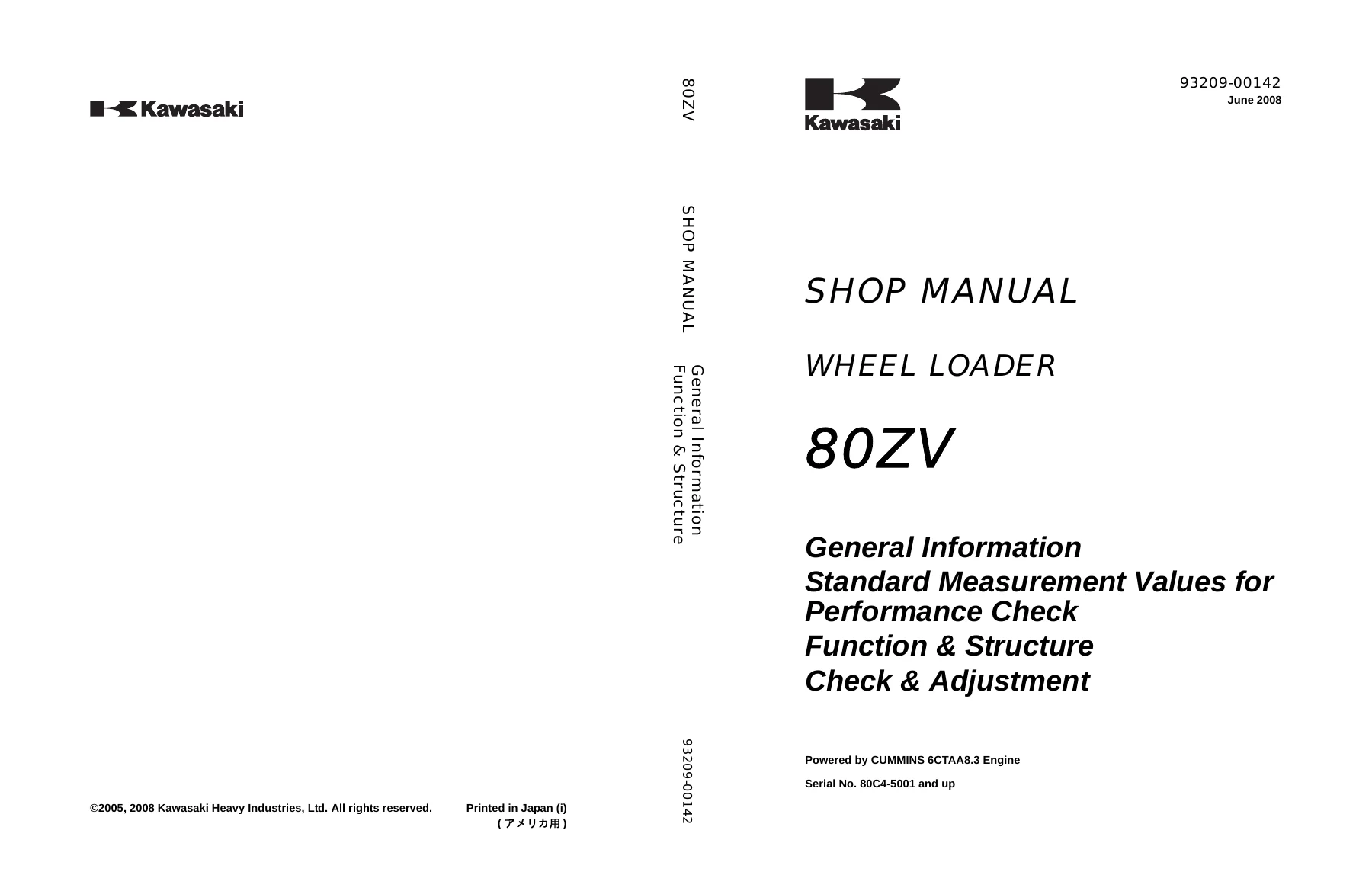
Kawasaki 80ZV Wheel Loader Shop Manual – 93209-00142 PDF Repair Guide
Original price was: $59.95.$39.95Current price is: $39.95.
Complete Kawasaki 80ZV Wheel Loader Shop Manual (93209-00142, June 2008) – 798-page PDF covering engine, transmission, hydraulics, brakes, electrical and air conditioner service, repair and troubleshooting.
Description
Kawasaki 80ZV Wheel Loader Shop Manual – Complete PDF Service Guide
This is the complete Kawasaki 80ZV Wheel Loader Shop Manual, document number 93209-00142, published June 2008. It is the comprehensive service and repair reference for the 80ZV wheel loader, covering every major system on the machine from the Cummins 6CTAA8.3 engine through the torque converter, transmission, hydraulics, brakes, electrical system, and optional air conditioner.
File Details
- Manual type: Shop Manual
- Brand/Model: Kawasaki 80ZV Wheel Loader
- Language: English
- Page count: 798
- File format: PDF
- Document number: 93209-00142
- Publication date: June 2008
Chapters Covered
- General Information
- Troubleshooting
- Measurement for Performance Check
- Chassis Group
- Power Group
- Torque Converter and Transmission Group
- Hydraulic Group
- Brake Group
- Electrical Group
- Air Conditioner Group
- Cross-Section Drawing & Diagrams
General Information
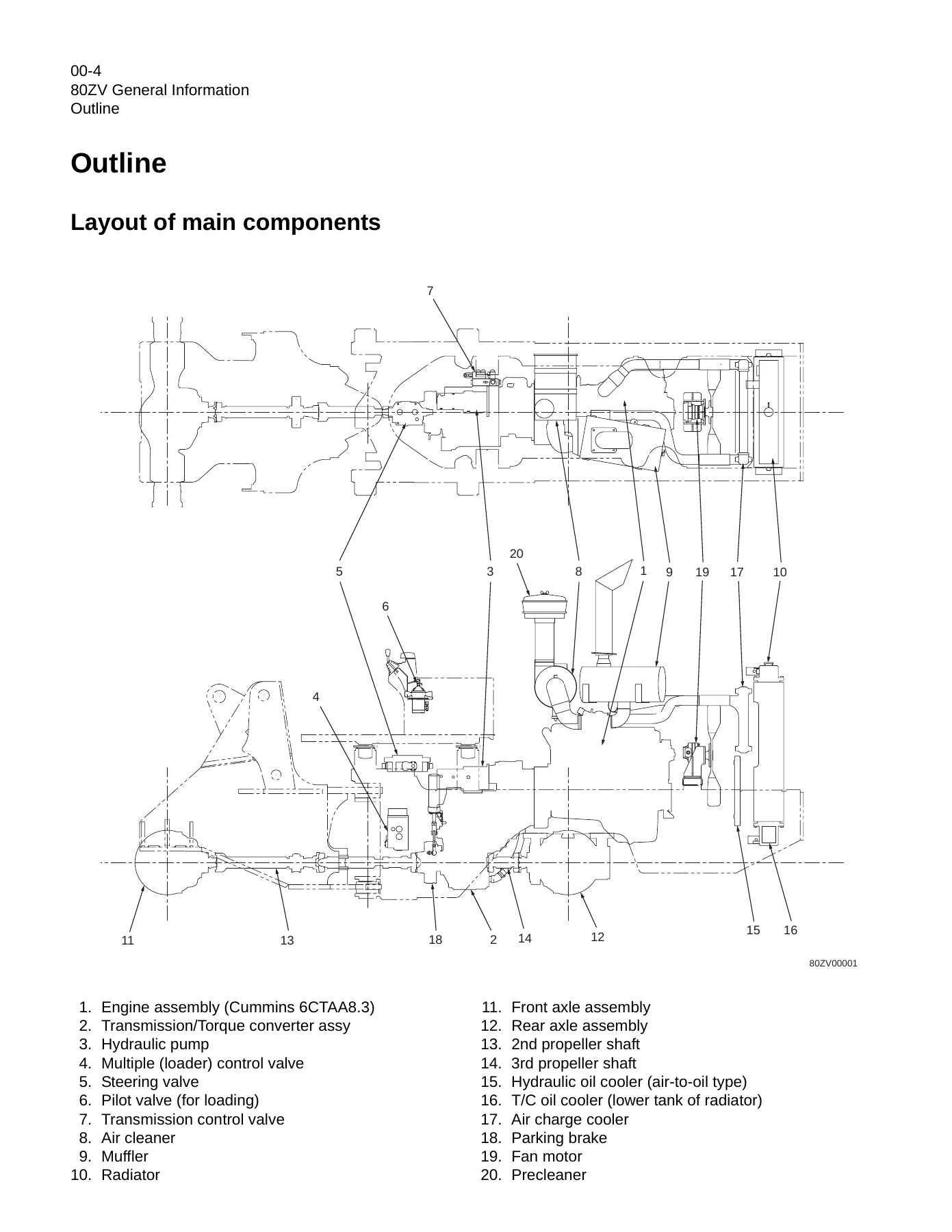
The opening chapter provides the foundation for all work on the 80ZV. It covers safety precautions, how to use the manual, the layout of main components with labelled illustrations, the inspection and maintenance table with service intervals, recommended lubricants and coolant specifications, weight of main components, and the complete bolt tightening torque tables for metric and unified threads. This is where you find the torque values, fluid capacities, and maintenance schedule before touching the machine.
Troubleshooting
This chapter is organized as a quick troubleshooting table covering the torque converter and transmission group, hydraulic group, brake group, and electrical group. Each problem is presented with symptoms, check points, possible causes, and solutions. For example, it covers what to check when the machine does not move in any shift lever position, when the boom or bucket has low power, when the brake drags, or when the instrument panel does not indicate properly. This section is designed for fast diagnosis in the field.
Measurement for Performance Check
Here you find the standard measurement values for performance checks, measurement conditions, and the procedures for measuring engine speed, clutch oil pressure and time lag, cylinder drift, boom cycle time, full steering cycle time, relief valve setting pressures, fan revolution, brake performance, brake line oil pressure, accumulator circuit charging time, number of brake pedal applications, and declutch engagement. These are the baseline values and test procedures used to determine whether the machine is performing to specification.
Chassis Group
The chassis group covers the front chassis, rear chassis, and center pin. It includes the loading linkage structure and pin specifications, the fuel tank and hydraulic tank details, the engine room, cab, floor board, and the center pin assembly with upper and lower pin configurations. The disassembly and reassembly procedures for the deck, fuel tank, hydraulic tank, engine room, cab, floor board, boom, and center pin are all included, along with the service standard clearances for linkage pins, center pin shim adjustment, and bucket positioner and boom kick-out settings.
Power Group
The power group covers the power line, radiator, engine, propeller shafts, air cleaner, muffler, front axle assembly, rear axle assembly, axle support, and differential assembly. It includes the engine and transmission mount details, radiator mount and capacity, propeller shaft alignment and phase, axle assembly with exploded views, axle support variations by serial number, and the torque proportioning differential (T.P.D.) function and operation. The disassembly and reassembly sections cover the front axle, internal gear hub, spider assembly, rear axle, axle support, and differential assembly with the special tools required.
Torque Converter and Transmission Group
This group covers the torque converter structure and power flow, the torque converter gear pump specifications, the transmission clutch combination and shift lever positions, the QUAD (Quick up and down shift) system, gear train and number of teeth, clutch specifications, and the clutch pack configurations for forward, reverse, 1st, 2nd, 3rd, and 4th speed clutches. It includes the power flow path in the transmission for all forward and reverse speeds, the hydraulic system diagram, hydraulic circuit diagram, oil flow through the torque converter and clutch circuits, the control valve, modulation mechanism with clutch control oil pressure curves, and the clutch solenoid valve operation. The disassembly and reassembly sections cover the torque converter assembly, transmission assembly, each clutch pack, and the control valve assembly with service standards for the transmission, control valve, gear pump, clutch plate thickness, piston stroke, and clutch oil pressure.
Hydraulic Group
The hydraulic group is extensive. It covers the flushing hydraulic circuit, cautions on hydraulic parts replacement, hydraulic circuit symbols, hydraulic system operation, layout of hydraulic units, the hydraulic tank with breather valve and specifications, hydraulic pump principle and wear plate, hydraulic cylinders for boom, bucket, and steering with cross-sections and torque values, the loading system with reducing valve and pilot valve, the multiple control valve (KML28/2T102) with main relief, overload relief, make-up valve, and spool operation, the adapter (orifice), ride control option, steering system with Orbitrol, steering valve (KVS25-A3.0/A4.0/20), stop valve, reducing valve, steering line filter, fan motor system with thermo sensing valve, and the reversing fan motor system option. The disassembly and reassembly sections cover the hydraulic pump assembly, hydraulic cylinders, pilot valve, multiple control valve, Orbitrol, steering valve, stop valve, and fan motor.
Brake Group
The brake group covers the brake system outline, brake units layout, unloader valve, valve unit, brake accumulator line, brake valve with main and pilot valve operation, service brake, parking brake, parking brake manual release, parking brake spring chamber, and brake circuit check valve. It includes the disassembly and reassembly of the unloader valve, manifold valve assembly, accumulator with nitrogen gas charging procedure, brake valve, service brake, park brake actuator, and parking brake. The service standards cover the brake valve, service brake, and parking brake with wear limits and adjustment values.
Electrical Group
The electrical group covers how to use electrical wiring diagrams, electrical cable color codes, electrical circuit symbols, sensor mount locations, fuse box and fusible link locations, engine start circuit with neutral starter, starter switch, accelerator pedal, fuel control, fuel solenoid valve, battery relay, diode unit, neutral relay, magnet switch, and voltage relay. It includes the power generating/charging circuit, transmission control circuit and monitor circuit with controller, LED indicators, controller function, automatic shift, machine speed sensor, QUAD switch operation, transmission cut off, back-up alarm, parking brake, transmission controller failure warning, monitoring system, instrument panel and switch, gauge circuit, fuel level sensor, electrical detent circuit for bucket leveler and boom kick-out, diode check methods, and the diagnostic system with failure history indication and deletion. The check and adjustment section covers electrical circuit checks for the shift lever, inching, QUAD switch, machine speed sensor, clutch solenoid valve, trimmer plug solenoid valve, neutral relay, parking brake, gauge circuit, and bucket positioner.
Air Conditioner Group
The air conditioner group covers the air conditioning system, 134A refrigerant compressor, compressor electromagnetic drive clutch, condenser, receiver/drier, thermostatic expansion valve, evaporator temperature sensor, evaporator, high and low pressure switches, automatic temperature control (ATC), ambient temperature probe, defroster and heater valve actuator motors, electrical connections, plug connections, maintenance, A/C charging, final inspection, appendix, and troubleshooting with code tables, problem diagnosis, and sensor resistance tables.
Cross-Section Drawing & Diagrams
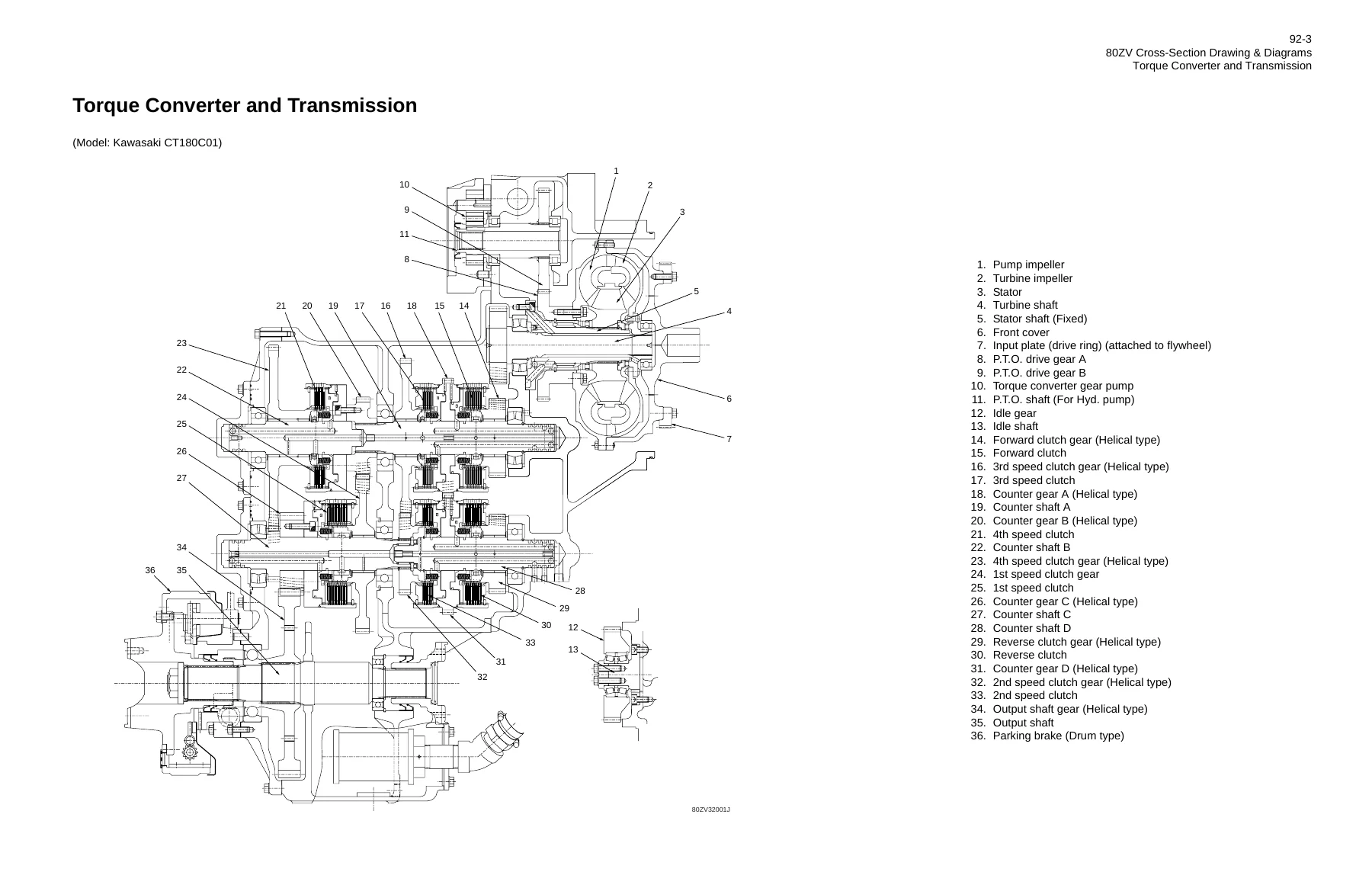
This final section contains the large cross-section drawings and diagrams that tie the whole manual together. It includes the axle assembly cross-section, torque converter and transmission cross-section, loading/steering hydraulic circuit, brake circuit, and the complete electrical wiring diagrams broken down by serial number ranges (S/N 5001-5050, 5051-5171, 5172-), plus the electrical wiring diagram abbreviation chart, reversing fan motor line option, cab wiring, electrical connection diagrams, and electrical equipment layout for front chassis, rear chassis, and floor board.
What This Kawasaki 80ZV Shop Manual Enables You to Do
With this Kawasaki 80ZV shop manual, you can perform the full range of service and repair work on the machine. That includes engine speed and oil pressure checks, clutch oil pressure and time lag measurements, cylinder drift tests, relief valve pressure adjustment, transmission clutch pack disassembly and reassembly, torque converter service, hydraulic pump and cylinder repair, multiple control valve service, brake system diagnosis and repair including accumulator charging, electrical troubleshooting down to individual circuit checks, and air conditioner diagnostics and charging.
Having the correct procedures and specifications matters on a machine like the 80ZV. Torque values, clearances, pressure settings, and adjustment procedures are all specified, and working without them risks damaging components, causing premature failure, or creating a safety hazard. The manual gives you the factory procedures for disassembly, inspection, repair, and reassembly, along with the service standards for judging wear and deciding what to replace.
This is the manual that Kawasaki service technicians use. It covers the Cummins 6CTAA8.3 engine and the Kawasaki CT180C01 torque converter and transmission, along with the hydraulic, brake, electrical, and air conditioning systems. Whether you are running a fleet of 80ZV wheel loaders, operating a single machine, or working in a repair shop, this Kawasaki 80ZV service manual provides the information needed to keep the machine running correctly.
IMAGES PREVIEW
Delivery is instant. After payment you receive the PDF download link immediately – no shipping, no waiting. You can view it on any device, search the text, and print the pages you need for the workshop. The PDF works on computers, tablets, and smartphones, and you can print specific pages or entire sections as required.
Reviews
There are no reviews yet.