Kodak DryView 8150 Laser Imager Service Manual – Complete Repair Guide
Original price was: $85.00.$20.95Current price is: $20.95.
Professional service manual for Kodak DryView 8150 laser imager (medical imaging equipment). Complete technical reference for medical professionals and biomedical technicians. Includes specifications, installation procedures, system adjustments, mechanical disassembly/reassembly, preventive maintenance, DICOM operation, troubleshooting guides, error code reference, and parts information. Covers 50 milliwatt laser system with densitometer, film processor, RF tag subsystem. November 2011 Revision
Description
Kodak DryView 8150 Laser Imager Service Manual - Complete Repair Guide PDF DOWNLOAD
DESCRIPTION
MANUAL DETAILS
| Specification | Details |
|---|---|
| Device Model | Kodak DryView 8150 Laser Imager |
| Device Classification | Medical Imaging Equipment (Laser Imager) |
| Manual Type | Professional Service Manual – Revision A |
| Publication Date | November 2004 (Rev. A) |
| Total Pages | 460 pages |
| File Size | 18.1 MB (optimized PDF) |
| Document Number | 1961259, 7F3318 |
| Publisher | Eastman Kodak Company |
| Regulatory Status | Safety Manual supplement (full Safety Manual available separately) |
KODAK DRYVIEW 8150 SPECIFICATIONS
| Feature | Specification | Details |
|---|---|---|
| Laser System | 50 milliwatt LASER | Class IIIb laser module |
| Film Sizes Supported | Multiple | Specified in film section (1-10) |
| Film Throughput | Industry-standard speeds | DICOM compliance capable |
| Operating Temperature | Specified range | See section 1-4 |
| Storage Temperature | Specified range | See section 1-3 |
| Operating Humidity | Specified range | Climate-controlled environment required |
| Altitude | 0 to specified elevation | Installation site requirement |
| Floor Vibration | Specified limits | Sensitive equipment – stable mounting required |
| Floor Levelness | Specified tolerance | Critical for optical alignment |
| Floor Load Capacity | Specified per site | Heavy medical equipment |
| Environmental Effects | Controlled conditions | HVAC/air quality management |
| Image Input Options | DICOM network | Multiple input sources supported |
| Network Interface | DICOM/TCP-IP | Enterprise healthcare IT integration |
COMPREHENSIVE COMPONENT SYSTEMS
| System | Components | Details |
|---|---|---|
| Film Processor Assembly | Processor Interface Board, Drum, Rollers, Motor, Kicker Motor, Film Diverter | Thermal processing system with temperature control |
| Roller Set Assemblies | Multiple roller configurations | Transport and positioning rollers |
| Densitometer Assembly | Module, Exit Sensor (S9), Light Source, Control Board | Optical density measurement and calibration |
| Local Panel | User interface module | Operator controls and display |
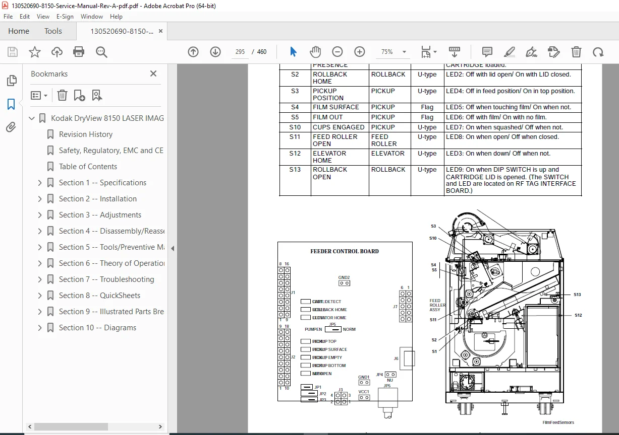
| Film Pickup Assembly | Module, Vacuum Cups, Heel Pad, Optical Sensors (S3-S5, S10), Motor, Vacuum Pump | Automated film feed system |
| Rollback Assembly | Module, Motor (DCM1), Cartridge Present Sensor (S1), Rollback Home Sensor (S2), Rollback Open Sensor (S13), RF Tag Assembly, RF Antenna Board | Supply cartridge management |
| Elevator Assembly | Module, Home Sensor (S12), Motor, Hub Assembly | Vertical film positioning |
| Feed Roller Assembly | Module, Open Sensor (S11), Open Motor (DCM4), Feed Motor, Torsion Springs | Film advancement mechanism |
| Vertical Transport | Module, Transport Sensor (S8), Transport Motor | Vertical film movement |
| Imaging (Exposure) Assembly | Module, Scanner, Platen Film Sensor (S6), Optics Home Sensor (S7), Optics Translation Motor, Film Centering Assembly, Platen Roller Motor, Nip Roller Belt, Platen Rollers, Vibration Mounts, Optics Module | Laser exposure and optical system |
| Power Assembly | AC/DC conversion, power distribution | Electrical system management |
| DICOM Raster Engine (DRE) Computer | CPU, Hard Drive, CD/Floppy Drives, PCIO Board, Ethernet Board, Local Panel Transmitter, DIMM Memory, Power Supply | Image processing and system control |
DICOM RASTER ENGINE (DRE) SOFTWARE ARCHITECTURE
| Component | Function | Details |
|---|---|---|
| PACSLink MIM | DICOM modality image management | Delivery interface, MPDB database |
| MCS Interface Server (MIS) | System control and communication | Image server, command server, service providers |
| MCS Database Server | Data storage and retrieval | Configuration and operational data |
| Web Server | Remote monitoring and control | Service laptop/Local Panel access |
| Browser Interfaces | User access points | Active Server Pages (ASP), data formatters |
| Machine Control System (MCS) | Hardware controller | Master/slave microprocessor system |
| Serial Communication Protocol | Device interconnection | UART circuit for MCS connection |
MACHINE CONTROL SYSTEM (MCS) COMPONENTS
| Component | Function | Notes |
|---|---|---|
| Master CPU | System processor | Controls all device functions |
| Film Processor Control | Temperature management | Thermal system regulation |
| Stepper Motor Drive | Motor control circuitry | Multiple motor management |
| Media Lookup Table (Linear LUT) | Film/media calibration | Device-specific settings |
| Laser Scanning Characteristics | Laser power control | Output modulation |
| Laser Optics Subsystem | Film platen, optics module, translation assembly | Exposure system |
| Densitometer Module | Optical measurement | Calibration via step wedge, Dpatch reading |
| RF TAG Subsystem | Cartridge identification | RFID technology for media tracking |
| Feeder Control Board | Film transport | Motor and sensor coordination |
| Processor Interface Board | Processor communication** | Drum temperature regulation (RTD) |
SYSTEM SENSORS & MONITORING
| Sensor | ID | Function | Location |
|---|---|---|---|
| Cartridge Present | S1 | Supply cartridge detection | Rollback module |
| Rollback Home | S2 | Rollback position verification | Rollback assembly |
| Film Pickup Sensor 1 | S3 | Film pickup positioning | Film pickup module |
| Film Pickup Sensor 2 | S4 | Film advance confirmation | Film pickup module |
| Film Pickup Sensor 3 | S5 | Film feed verification | Film pickup module |
| Platen Film Sensor | S6 | Film positioning on platen | Exposure/imaging module |
| Optics Home Sensor | S7 | Optics module home position | Imaging assembly |
| Vertical Transport Sensor | S8 | Transport position verification | Vertical transport module |
| Densitometer/Exit Sensor | S9 | Output film detection | Densitometer assembly |
| Film Pickup Sensor | S10 | Film engagement | Film pickup module |
| Feed Roller Open Sensor | S11 | Feed roller status | Feed roller assembly |
| Elevator Home Sensor | S12 | Elevator reference position | Elevator assembly |
| Rollback Open Sensor | S13 | Rollback open position | Rollback assembly |
INSTALLATION & CONFIGURATION PROCEDURES
The manual includes comprehensive instructions for:
- Checklist of installation procedures (Section 2-1)
- Tools required for installation (Section 2-2)
- Uncrating and initial setup with detailed visual aids
- Opening shipping crate and completing uncrating
- Removing laser imager from pallet
- Checking accessory materials
- Moving imager to installation site
- Checking site readiness and configuration requirements
- Unpacking procedures (front/back sections)
- Charcoal filter installation
- Connecting electrical power (AC power setup, external power connection)
- Connecting to network (DICOM/Ethernet)
- Securing imager in operating position
- Power-on procedures and initial startup
- Configuration of host name and IP address
- “Secure Tunnel” port number verification
- System clock setting
- DICOM source communications setup
- Service tracking configuration
- SCP Services configuration
- Imager destination configuration
- Local panel configuration
- Film type selection
- Remote monitoring (RMS) setup and grouping
- Operator training procedures
- Processor temperature verification
- Image quality checking and validation
- System configuration backup
- Service history log editing
- TFT set selection guidelines (DICOM/GSDF compliance)
- Image quality parameters for various medical modalities
ADJUSTMENTS & CALIBRATION
Section 3 covers critical adjustments including:
- Processor drum temperature setting (RTD calibration)
- Processor film diverter assembly (stripper) positioning
- Optics translation speed and SOP delay tuning
- Reference level for densitometer calibration
- Dynamic range of laser system
- Optics laser power adjustment and optimization
DISASSEMBLY/REASSEMBLY PROCEDURES
Over 50 detailed procedures covering:
- Front door and rear panel assemblies
- Film processor components (drum, rollers, motors, interface board)
- Densitometer module and sensors
- Local panel assembly
- Film pickup system (module, cups, sensors, motor, vacuum pump)
- Rollback assembly with all motors and sensors
- Elevator assembly components
- Feed roller system with all motors and springs
- Vertical transport assembly
- Complete imaging/exposure assembly
- Power assembly
- DICOM Raster Engine (DRE) computer components
- All circuit boards and memory modules
PREVENTIVE MAINTENANCE & CLEANING
- PM intervals and scheduling (Event calls, 20,000 cycle PM)
- Supplies required for maintenance
- Exposure platen cleaning procedures
- Front door air filter replacement
- Charcoal filter replacement
- Processor drum removal and inspection
- Drum, heat shield, and processor roller cleaning
- Film diverter assembly cleaning
- Processor gasket replacement
- Complete drum reinstallation
- Optics module cleaning procedures
THEORY OF OPERATION
Comprehensive coverage of:
- DICOM Raster Engine (DRE) hardware architecture
- DRE computer hardware components
- Local panel interface
- Image processing in main memory
- PCIO board (digital output, serial communication)
- DRE software components and hierarchy
- PACSLink MIM delivery system
- DICOM modality preferences database
- MCS Interface Server functions
- MCS database architecture
- Web server and browser interfaces
- Machine Control System (MCS) design
- Master/slave microprocessor protocols
- MCS board components and functions
- Laser optics subsystem operation
- Densitometer calibration and operation
- RF TAG subsystem components and commands
- Feeder control board operations
- Processor interface board functions
- DC power supply specifications
- Complete print sequence of operation
- Special service mode operations
- AIQC (Automatic Image Quality Control) procedures
- GSM (Gray Scale Modulation) procedures
- Power-up, calibration, and complete print sequence
TROUBLESHOOTING & DIAGNOSTICS
- General troubleshooting table and flowcharts
- Service WebLink/Service Tool access procedures
- Setting active controls
- Network configuration for service tools
- Densitometer testing procedures
- FRU (Field Replaceable Unit) diagnostics
- Mechanical diagnostics and tests
- Optics system testing
- Sensor testing procedures
- Film data acquisition
- Dpatch data collection
- Film calibration data plotting
- Local panel testing
- DRE test print execution
- MCS transport testing
- Diagnostics summary reports
- Network communication testing
- Image problem source identification
- Configuration backup/restore procedures
- DRE software upgrade procedures (ghosting)
- Power-on self-test (POST) flow charts
- Sensor LED testing procedures
- Film transport problem troubleshooting
- Film scratch source identification
- Operator interview guidelines
- Visual inspection procedures
- Module removal and inspection protocols
- Direct MCS cable monitoring via COM port
- Log analysis and usage:
- Application Log (with advanced filtering)
- DICOM Log
- Error Tally
- IIS Log
- Local Panel Log
- MCS Log
- NT Event Log (Application & System)
- Print Delivery Log
ERROR CODES & QUICK REFERENCE
Complete QuickSheets for:
- DICOM status messages
- Local panel status messages
- Error severity levels
- Subsystem error categories:
- 00-099 through 00-530: General PACS subsystem
- 01-001 through 01-910: Service subsystem
- 03-111: Rendering errors
- 03-381 through 03-912: Routing/Delivery subsystem
- 04-004 through 04-215: DICOM/Network subsystem
- 05-000 through 05-044: Storage subsystem
- 10-001 through 10-910: Delivery server errors
- 12-001 through 12-075: Local panel errors
- 13-001 through 13-003: Service tool software errors
- 20-137 through 20-913: Door, override, and data transfer errors
- 21-114 through 21-179: Film pickup and cartridge transport errors
- 21-515 through 21-632: Calibration and densitometer errors
- 21-921 & 25-922: Feeder and RF tag subsystem errors
FILE SPECIFICATIONS SUMMARY
- Device Type: Medical Laser Imager (DICOM-compliant)
- Application: Diagnostic imaging output to film media
- Document Format: 460 pages, 18.1MB professional PDF
- Technical Level: Enterprise medical device service documentation
- Coverage: Complete system (laser, optics, film processor, electronics, DICOM interface, software)
- Industry: Healthcare/Biomedical equipment service
- Audience: Authorized service technicians, biomedical technicians, hospital IT/engineering staff