Kodak DryView 8150 Laser Imager Service Manual – Full OEM PDF
Original price was: $60.00.$21.95Current price is: $21.95.
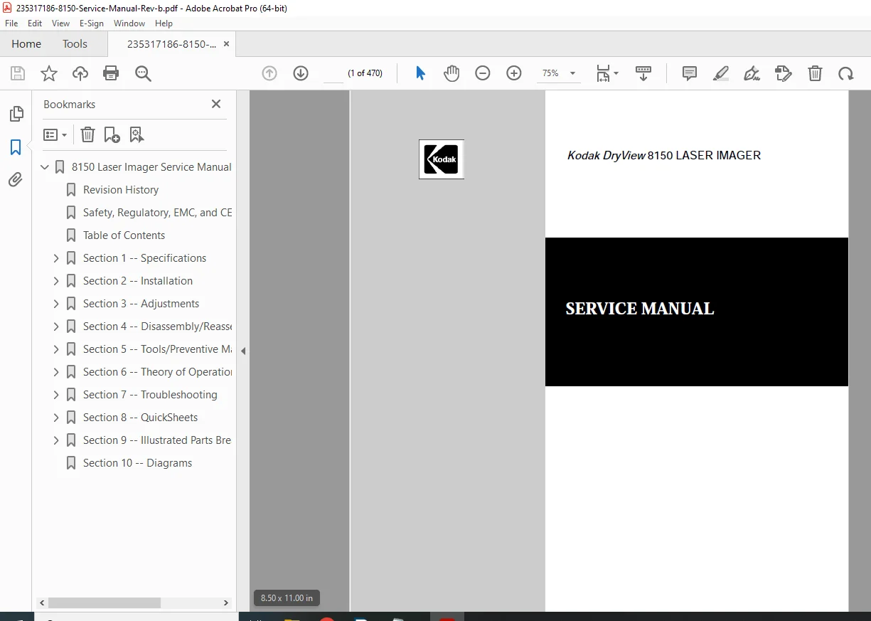
Factory Kodak DryView 8150 Laser Imager Service Manual (Rev. B, 2005). Includes complete installation, calibration, preventive maintenance, disassembly, DICOM setup, and troubleshooting. Contains full schematics, diagnostics, and QuickSheets for error codes and service flowcharts. Designed for authorized service engineers and biomedical technicians.
Description
Kodak DryView 8150 Laser Imager Service Manual – Full OEM PDF
IMAGES:
Description
The Kodak DryView 8150 Laser Imager Service Manual is the official factory document used by Kodak-certified service engineers.
It provides complete coverage of installation, configuration, calibration, component replacement, preventive maintenance, system theory, and troubleshooting for the DryView 8150 Medical Laser Imager.
This manual is essential for maintaining optimum image quality and laser reliability, offering detailed diagnostic procedures for the DICOM Raster Engine, Machine Control System (MCS), and Optics Subsystems.
Table of Contents
Section 1 – Specifications
1.1 Product Description
1.2 Physical Dimensions & Weight
1.3 Environmental Requirements
1.4 Power Supply & Electrical Ratings
1.5 Film Handling Capability
1.6 DICOM Network Interfaces
1.7 Performance Characteristics
1.8 Compliance & Safety Labels
Section 2 – Installation
2.1 Site Preparation Checklist
2.2 Power Connection and Voltage Settings
2.3 Uncrating and Moving the Imager
2.4 Leveling, Ventilation, and Clearance
2.5 Network Cabling and DICOM Setup
2.6 Verifying Software and Firmware Versions
2.7 Post-Installation Tests and Verification
2.8 Operator Orientation
Section 3 – Adjustments
3.1 Laser Power Calibration
3.2 Drum and Transport Speed Adjustment
3.3 Film Density and Densitometer Calibration
3.4 Alignment of Optics Assembly
3.5 AIQC (Automatic Image Quality Control) Setup
3.6 Temperature and Sensor Offset Adjustment
3.7 Electrical Grounding Verification
Section 4 – Disassembly / Reassembly
4.1 Safety Precautions and ESD Protection
4.2 Removing the Top Cover, Front Door, and Side Panels
4.3 Film Processor Module
4.4 Pickup and Feed Rollers
4.5 Elevator Assembly and Film Path
4.6 Exposure Assembly and Laser Optics
4.7 Densitometer & RF Tag Reader
4.8 Drive Motors and Belts
4.9 Power Supply Unit and DRE Computer
4.10 Reassembly and Alignment Procedures
Section 5 – Preventive Maintenance (PM)
5.1 Preventive Maintenance Intervals
5.2 Cleaning Procedures (Optics, Drum, Air Filters)
5.3 Replacing Consumables (Filters, Rollers, Belts)
5.4 Lubrication Points and Schedules
5.5 PM Verification Checklist
5.6 Resetting Counters After PM
Section 6 – Theory of Operation
6.1 System Overview
6.2 DICOM Raster Engine (DRE) – Hardware Layout
6.3 Machine Control System (MCS) Architecture
6.4 Power Distribution and Interlocks
6.5 Laser Optics Subsystem
6.6 Film Transport & Pickup System
6.7 Densitometer Subsystem
6.8 Cooling and Air Flow Control
6.9 Automatic Image Quality Control (AIQC) Function
6.10 GSM & RF Tag Communication
Section 7 – Diagnostics
7.1 Entering Service Diagnostics Mode
7.2 MCS Board Self-Test
7.3 DRE Network Test and Log Retrieval
7.4 Sensor Monitoring Using LEDs
7.5 Drive and Motor Test Routines
7.6 Optics Calibration and Laser Modulation Test
7.7 Film Path Verification Routine
7.8 Print and DICOM Interface Tests
7.9 Saving and Transferring Log Files
Section 8 – Troubleshooting
8.1 Troubleshooting Overview
8.2 Error Code Summary (00–21 Series)
8.3 Mechanical Failures – Transport & Elevator
8.4 Optical Faults – Laser, Mirrors, Lenses
8.5 Electronic Faults – Power Supply, MCS, DRE
8.6 Communication Errors (Network, DICOM, RMS)
8.7 AIQC and Density Variance Problems
8.8 Reboot and Recovery Procedures
8.9 Flowcharts and Fault Isolation Tables
Section 9 – QuickSheets / Error Codes
9.1 Quick Reference Fault Table
9.2 Error Number Definitions
9.3 Common Symptoms vs. Corrective Actions
9.4 Service LED Blink Codes
9.5 Film Handling Failure Map
9.6 DICOM Message Failures
Section 10 – Replacement Procedures
10.1 Removing Subassemblies
10.2 Installing Replacement Modules
10.3 Optical Alignment After Replacement
10.4 Cable Routing and Connector Pinout Tables
10.5 ESD Safe Handling Guidelines
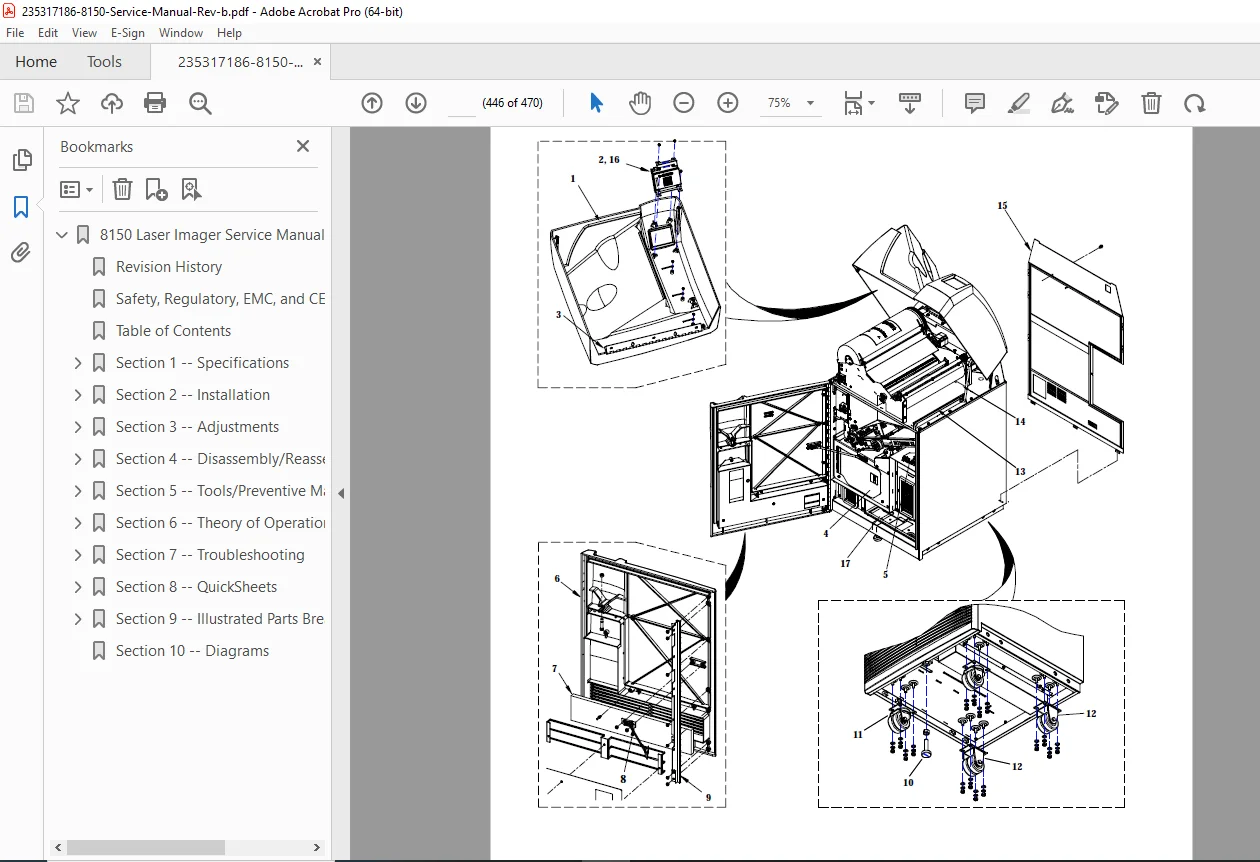
Section 11 – Parts List and Exploded Diagrams
11.1 Exploded Mechanical Diagrams
11.2 PCB and Cable Layout Drawings
11.3 Electrical Schematic Overview
11.4 Recommended Spare Parts List
11.5 Part Number Index
Section 12 – Appendices
A. System Configuration Printouts
B. Service WebLink Usage
C. RMS (Remote Maintenance System) Configuration
D. DICOM Error Message Tables
E. Firmware Revision History
F. Glossary & Abbreviations
⚙️ Key Highlights
Covers laser optics, film transport, densitometer, and RF tag systems
Includes complete electrical and mechanical diagrams
Explains DICOM configuration and secure network communication
Features calibration flowcharts and maintenance checklists
- Designed for hospital biomed technicians and Kodak field engineers
Details
| Manual Name | Kodak DryView 8150 Laser Imager Service Manual – Revision B |
|---|---|
| Models Covered | DryView 8150 Laser Imager |
| Year | 2005 (July Rev. B) |
| PDF Quality | Factory OEM scanned + searchable with illustrations and flowcharts |
| Total Pages | 470 pages (12 Sections + Appendices) |