
Komatsu 125E-6 Series Engine Shop Manual – SAA6D125E-6 Diesel Service, Repair & Maintenance PDF
Original price was: $52.95.$34.95Current price is: $34.95.
Complete Komatsu 125E-6 Series Engine Shop Manual (SEN05624-03) for the SAA6D125E-6 diesel engine. 340-page PDF covering specifications, structure and function, standard values, disassembly and assembly, and maintenance standards for PC490LC-10, HM300-3, and WA470-7.
Description
This Komatsu 125E-6 Series Engine Shop Manual is the complete service, repair, and maintenance reference for the SAA6D125E-6 six-cylinder diesel engine used across Komatsu’s PC490LC-10 hydraulic excavator, HM300-3 articulated dump truck, and WA470-7 wheel loader. Issued under document number SEN05624-03, the 340-page PDF walks through every major engine system — from the KVGT variable geometry turbocharger and high-pressure common rail fuel system to the EGR cooler, KCCV crankcase ventilation, and KDPF diesel particulate filter that define this Tier 4 engine platform. Whether you are diagnosing a fuel pressure fault, setting valve clearance, pulling a cylinder head, or measuring crankshaft end play, the procedures, values, and illustrations in this Komatsu 125E-6 engine shop manual are the ones the workshop floor actually needs.
File Details
- Manual type: Engine Shop Manual
- Brand: Komatsu
- Model: 125E-6 Series
- Engine: SAA6D125E-6
- Language: English
- Page count: 340
- File format: PDF
- Document number: SEN05624-03
- Date: 2017
Chapters Covered
- 00 Index and Foreword
- 01 Specification
- 10 Structure and Function
- 20 Standard Value Table
- 50 Disassembly and Assembly
- 60 Maintenance Standard
01 Specification
The specification chapter lays out the SAA6D125E-6 engine’s physical and performance envelope. You get the overall dimensions (length, width, height with and without exhaust pipe) for each of the three machine applications — PC490LC-10, HM300-3, and WA470-7 — plus rated horsepower, maximum torque, high-idle and low-idle speeds, dry weight, fuel consumption ratio, lubricating oil refill capacity, coolant quantity, alternator and starting motor ratings, and turbocharger model. The chapter also reproduces the engine performance curves (flywheel horsepower and torque against engine speed) for each machine and includes the applicable-machines table that ties the engine serial number range to the machine models. A weight table breaks down the major components — turbocharger, cylinder head, cylinder block, flywheel, crankshaft, camshaft, and so on — so you know exactly what you are lifting before you rig it.
10 Structure and Function
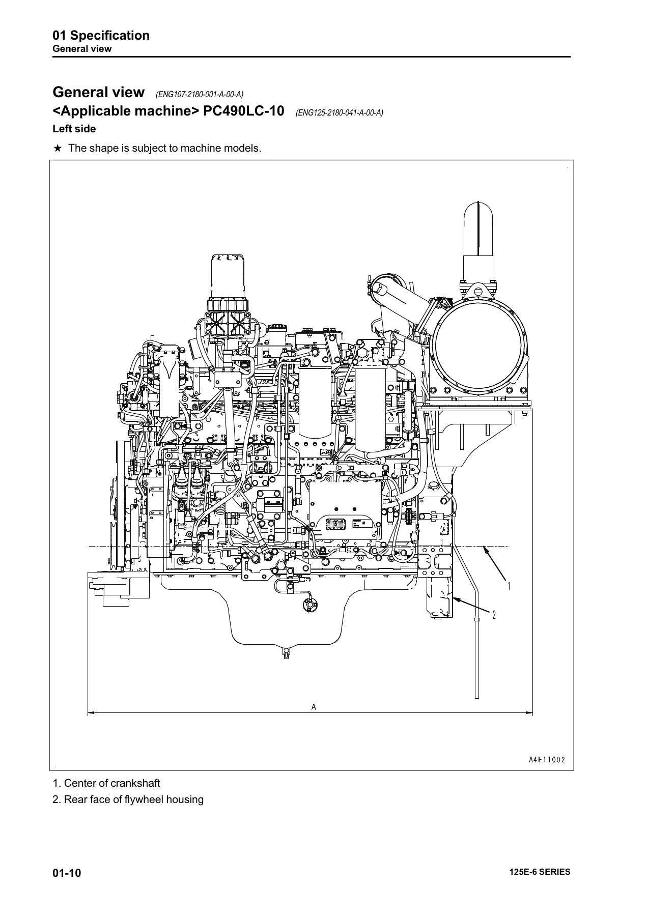
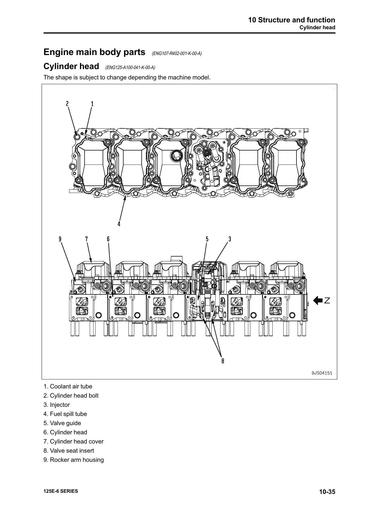
This is where the manual explains how the engine and its subsystems actually work, and it is the chapter that pays off every time a fault code sends you looking for the component that generates the signal. It opens with a components layout drawing of the complete engine, then works through the intake and exhaust system — air cleaner, KVGT, aftercooler, EGR valve and cooler, mixing connector, KCCV ventilator, and KDPF — with circuit diagrams and sectional illustrations. The KVGT section covers the variable nozzle mechanism, hydraulic actuator, EPC valve, and position sensor; the EGR section covers the hydraulically driven valve, the EGR cooler’s flat-tube construction, and the mixing connector that blends cooled EGR gas with intake air. The KDPF section explains the KDOC oxidation catalyst and KCSF soot filter, the three temperature sensors, the differential pressure sensor, and the passive, active, and manual stationary regeneration strategies. The engine main body section covers the cylinder head, cylinder block, main moving parts, vibration damper, timing gear, front cover, valve system, and flywheel housing. The lubrication, fuel, cooling, and electrical chapters follow, with the fuel system giving full treatment to the CRI (Common Rail Injection) system: supply pump with PCV pre-stroke control valve, common rail with flow damper and pressure limiter, injector operation with the two-way solenoid valve and control chamber, and the fuel doser circuit used during KDPF regeneration. The electrical section covers the alternator (50A, 60A, and 90A variants), the starting motor options (7.5 kW and 11 kW), the engine wiring harness, the CM2250 engine controller, and the full sensor list — KVGT speed and position, KDOC inlet/outlet temperature, KDPF differential and outlet pressure, crankcase pressure, manifold pressure, coolant temperature, oil level, air cleaner clogging, common rail pressure, ambient pressure, NE and backup speed, oil pressure, mass air flow and temperature, EGR valve lift, charge temperature, and dosing fuel pressure.
20 Standard Value Table
The standard value chapter is the book’s quick-reference line for testing and adjusting. It tabulates the new-machine standard and repair limit for engine speed (high idle and low idle), air intake resistance, boost pressure at rated horsepower, exhaust gas temperature, exhaust gas color (Bosch index at engine outlet and KDPF outlet), valve clearance for intake and exhaust, EGR valve and KVGT oil pressure at high and low idle, compression pressure, blowby pressure, oil pressure at rated horsepower and low idle, oil temperature, oil consumption, and alternator belt tension. Values are given separately for PC490LC-10, HM300-3, and WA470-7 where the machine-specific rating changes them. The chapter also includes the running-in standard and the performance test standard, with the dynamometer load, output, torque, coolant temperature, lubricating oil temperature, lubricating oil pressure, and exhaust temperature that each test step calls for.
50 Disassembly and Assembly
The disassembly and assembly chapter is the working procedure section. It starts with general disassembly of the engine — preparation, setting the engine on a stand, draining coolant and oil, and then a step-by-step removal sequence for the KDPF bracket, starting motor, alternator and belt tensioner, KVGT hydraulic actuator oil tube, EGR cooler, KVGT and exhaust manifold assembly, wiring harness, oil filter, fuel pre-filter and main filter, dosing fuel solenoid valve assembly, KCCV ventilator, EGR valve, mixing connector, fuel spill tube, high-pressure fuel pipes, air intake manifold, engine controller and cooler, common rail, supply pump assembly, fuel block, dipstick pipe, oil cooler, cylinder head cover, fuel injector wiring harness, rocker arm and shaft assembly, push rods, fuel injectors, crossheads, rocker arm housing, thermostat housing and water pump, front hanger, cam follower covers and cam followers, cylinder head assembly, and then the internal components down to the crankshaft and cylinder liners. General assembly follows in the reverse order with the specified torques, coating agents, and tightening sequences — including the torque-plus-angle method for cylinder head, main cap, and connecting rod cap bolts. The chapter also has dedicated procedures for removing and installing the supply pump as a single component, replacing the engine front oil seal, and replacing the engine rear oil seal (both the standard and sleeved oil seal variants).
60 Maintenance Standard
The maintenance standard chapter gives the wear limits and repair criteria for every major component group. Under intake and exhaust you get KVGT radial play, end play, and the KVGT operation check. Under engine main body parts you get cylinder head distortion, nozzle protrusion, cylinder head bolt tightening torque, cylinder block distortion, main metal bore and inside diameter, cam bushing bore and inside diameter, main cap bolt torque, oil pan bolt torque, crankshaft pulley bolt torque, and the level differences between cylinder block and flywheel housing and between cylinder block and front cover. The cylinder liner section gives protrusion limits, inside diameter ranks (A and B), roundness and cylindricity, outside diameter at the counterbore, bottom of counterbore, and O-ring portion, plus the interference and clearance values. Crankshaft, cam follower and push rod, piston, connecting rod, vibration damper, timing gear, camshaft, valve and valve guide, rocker arm, crosshead and guide, flywheel, main relief valve, safety valve, oil cooler thermostat, water pump, and thermostat all get their own tables of standard dimension, tolerance, repair limit, and remedy.
Applications and Engine Technology
The SAA6D125E-6 is a Tier 4 emissions engine, and the shop manual reflects that in the systems it covers. The KVGT variable geometry turbocharger adjusts the exhaust inlet passage area to build boost pressure even at low engine speed, which is what allows a high EGR ratio without sacrificing response. The EGR system sends a portion of exhaust gas back through the EGR cooler and mixing connector into the intake manifold to suppress NOx formation. The KCCV closed crankcase ventilation system filters oil out of blowby gas and returns the cleaned gas to the intake side of the KVGT. The KDPF diesel particulate filter captures soot in the KCSF and burns it off through passive regeneration (when exhaust temperature is high enough), automatic active regeneration (engine controller raises exhaust temperature and the fuel doser injects fuel), or manual stationary regeneration (operator-initiated from the machine monitor). Each of these systems has its own section in the structure and function chapter and its own service procedures in the disassembly and assembly chapter, with the relevant sensor and actuator tests in the standard value and maintenance standard tables.
Who This Manual Is For
This is a working shop manual for technicians, fleet maintenance departments, and owner-operators who service the SAA6D125E-6 engine in the PC490LC-10, HM300-3, or WA470-7. It is not a generic diesel engine primer — it is the Komatsu-specific document that tells you the torque value for the cylinder head bolts on this engine, the repair limit for the crankshaft main journal, the tightening sequence for the flywheel housing, and the part number of the special tool that presses in the rear oil seal. If you are rebuilding, resealing, diagnosing, or just maintaining one of these engines, this is the reference that keeps the work inside the manufacturer’s specifications.
Get the Komatsu 125E-6 Series Engine Shop Manual
IMAGES PREVIEW
You get the complete 340-page Komatsu 125E-6 Series Engine Shop Manual as an instant PDF download — no shipping, no waiting, no physical binder to lose. The file opens on any laptop, tablet, or phone, and the pages print cleanly for the shop floor. Keep a copy on the service truck, another on the office computer, and a printed set in the workshop. Every procedure, torque value, clearance, and diagnostic step for the SAA6D125E-6 engine is in one document, ready the moment you need it.
Reviews
There are no reviews yet.